

Crash repair
#31
 09-05-2009, 12:41 PM

The following guides are not finished
I am posting them and will edit each later.. just have some time to kill right now and wanted to get started on this.
Brakes
Tools needed
7mm Hex
lug wrench
screwdriver
C clamp
loosen lug nuts
Jack up and secure truck with jack stand
remove lug nuts and tire
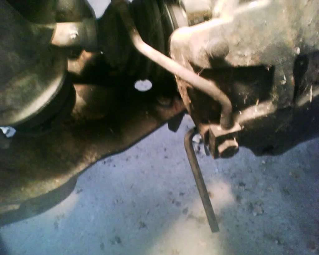
loosen the two hex bolts on the back of the brake caliper using a 7mm hex.
pic
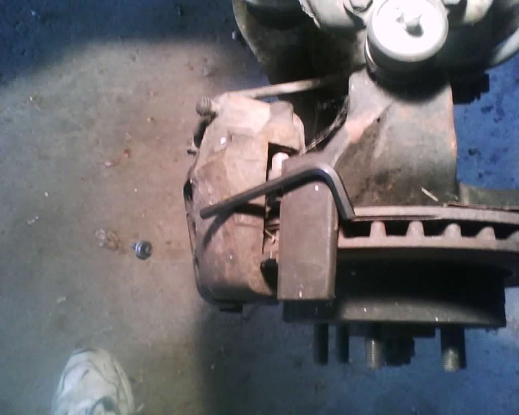
top one
pic
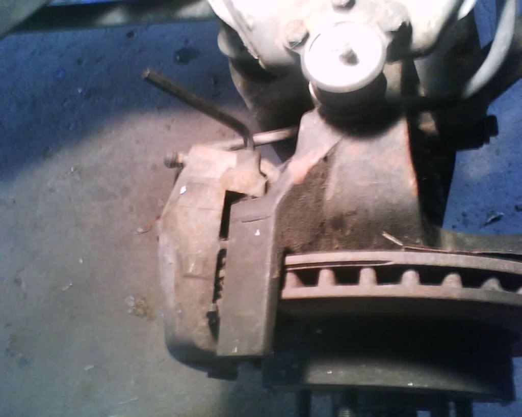
bottom one
pic
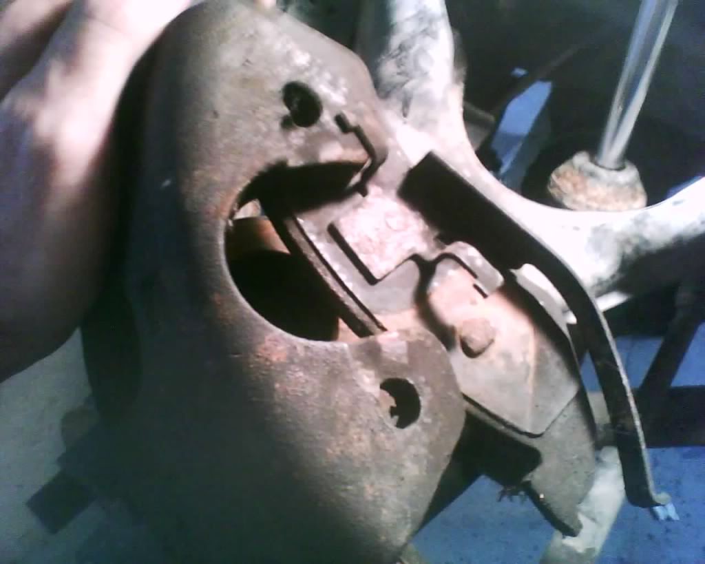
Now wiggle the caliper off (you may have to pull out on the blots you just loosened in order for it to clear the holes) and you have this
pic
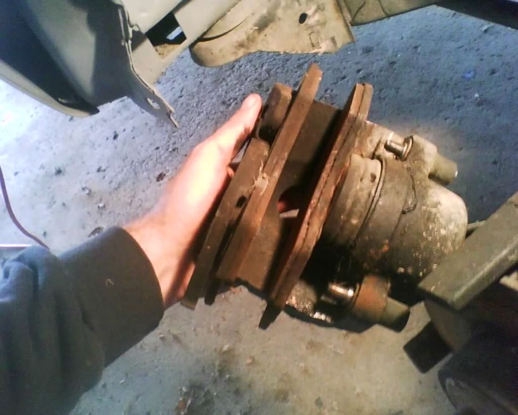
Remove the pads
pic
open the master cylinder to release pressure when pushing the piston back in,
pic
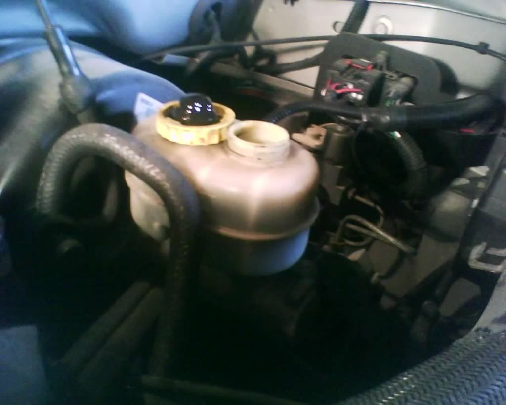
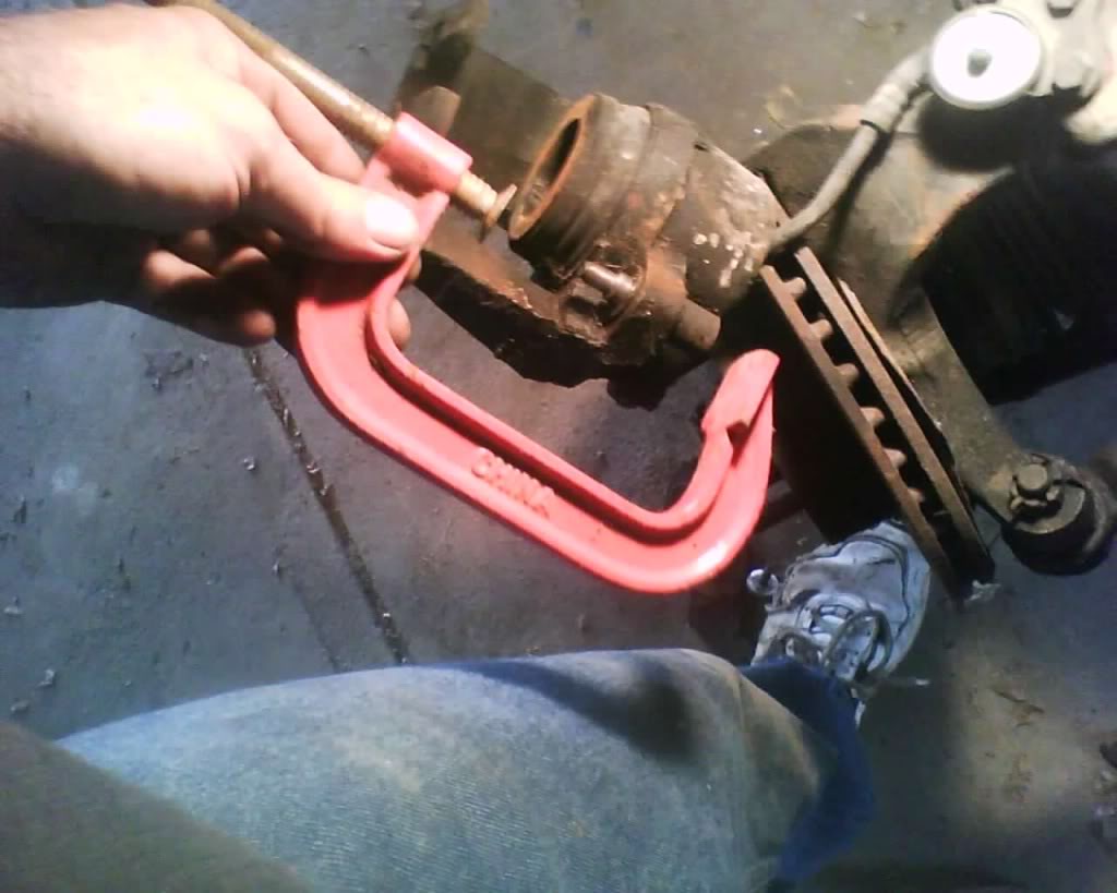
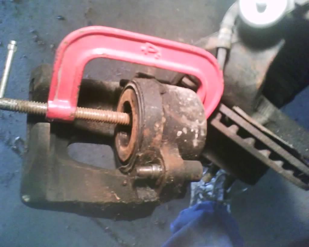
Grab a C clamp and slowly squeeze the piston all the way back in like so
I should add here that the proper way to do this is to remove the brake line from the caliper and push the piston back in pushing the fluid out threw the hole in the caliper where the brake line goes in. this would be the proper way. the way I did it is MY way and carries a risk u may damage the master cylinder doing. ( i will post simulated pics of the correct way upon installation
pic
I should note do NOT buy anything made in china if you can help it (talking about my c clamp) I actually remember this day and looked for an American made clamp and was not able to.. was not going to drive 20 miles to indy to sears to get one.
pic
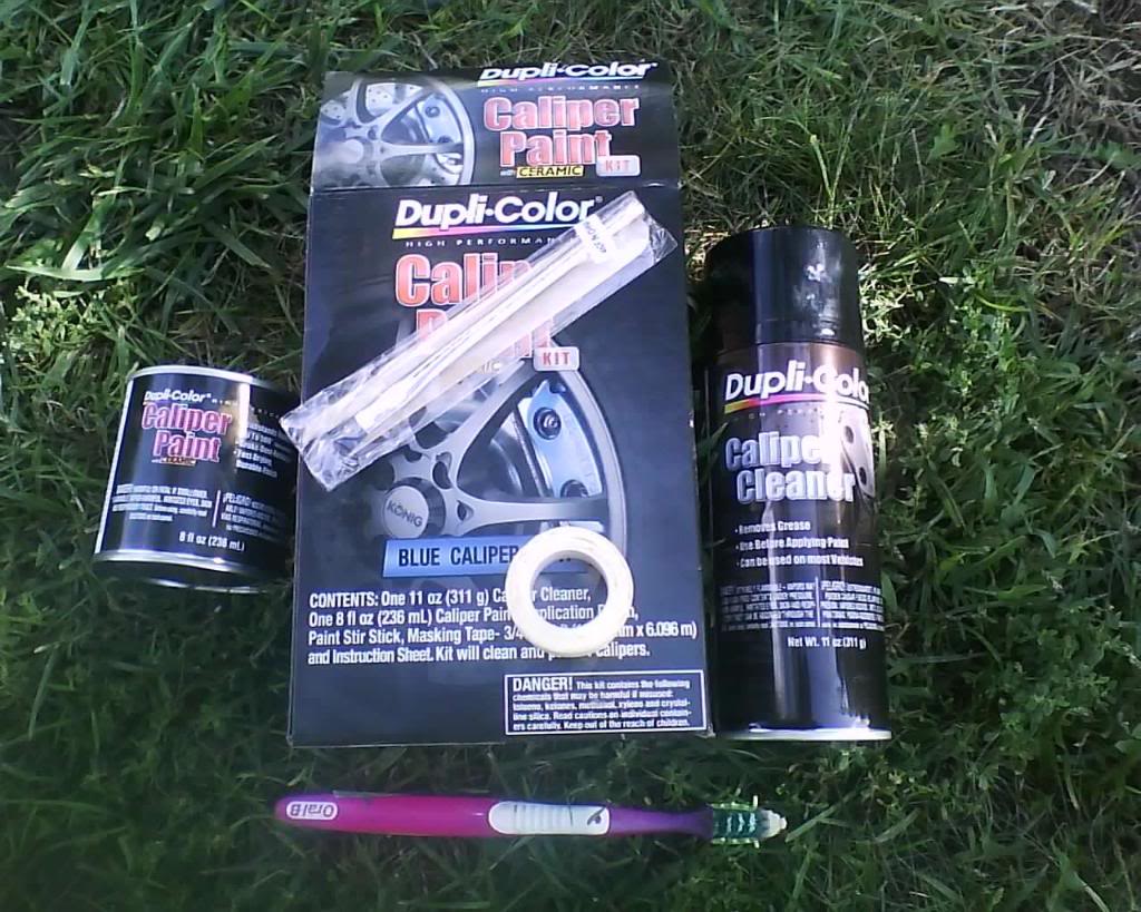
Okay if your here why not make this caliper look better? if you do then here is how.
about $20 for this kit
Follow instruction like so (mask if you want to but if you careful not needed)
pic
Clean REALLY good, this is the key to getting a good look and making the paint stick well
pic
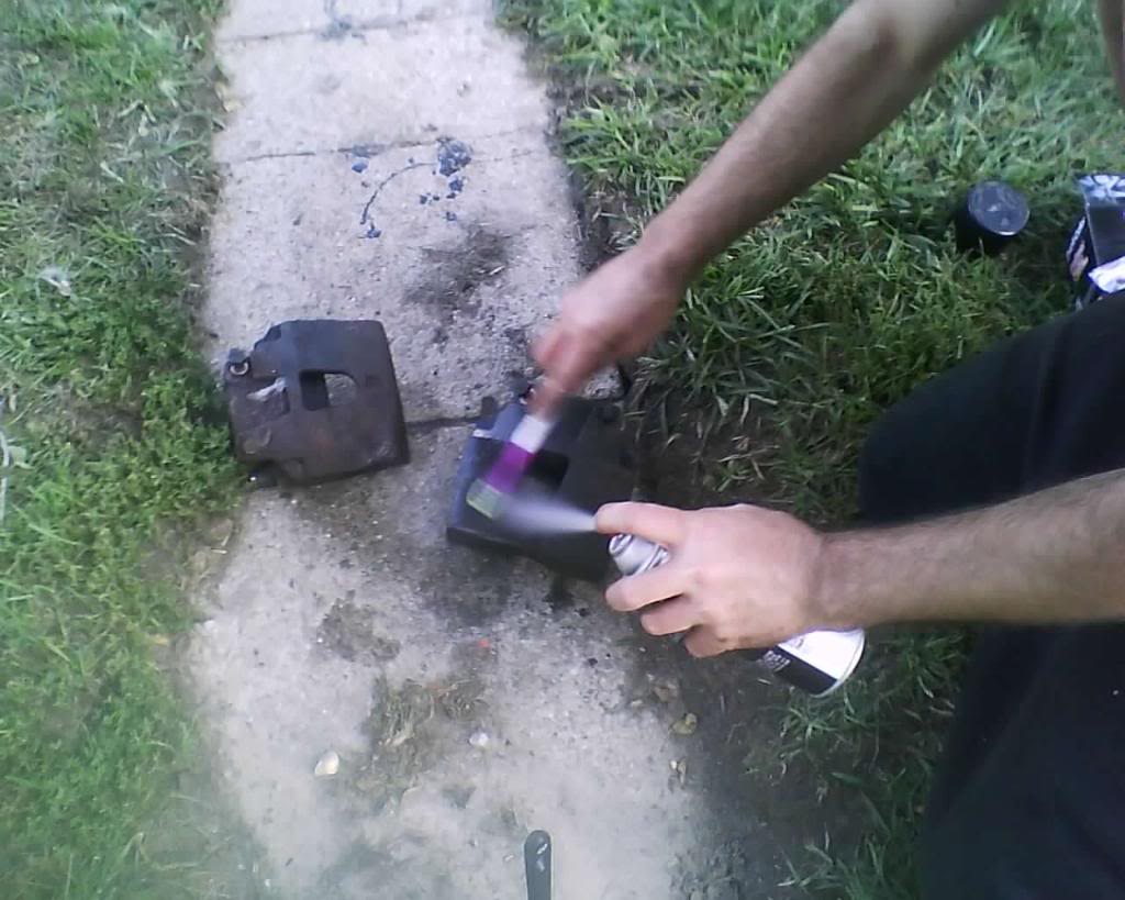
Paint
pic
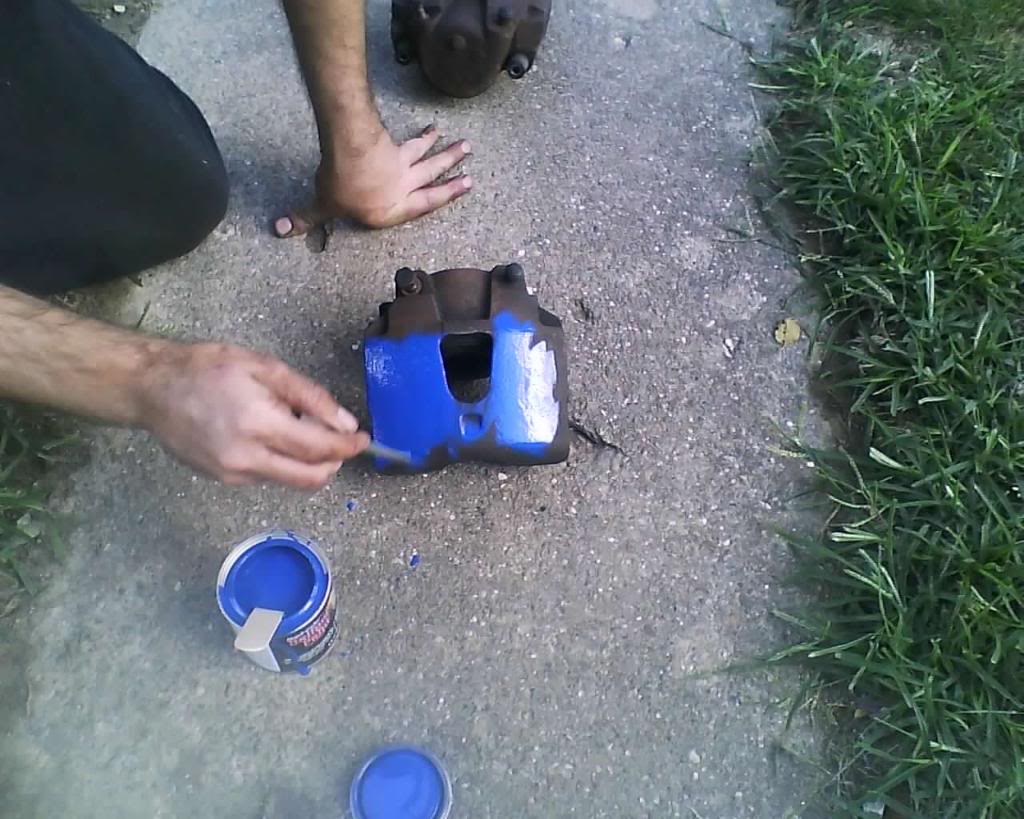
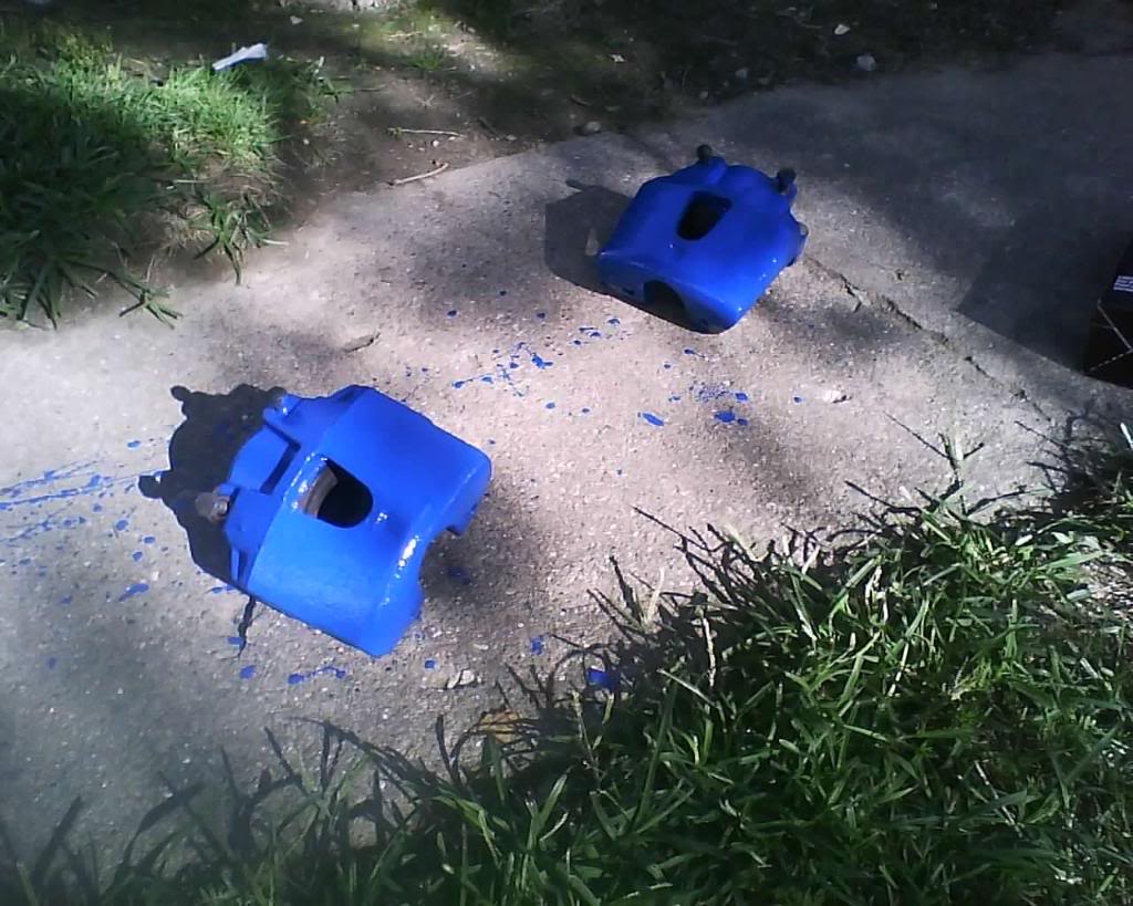
finished with painting the calipers
pic
okay back to the reinstall of the brakes
you will want to check where the pad touches for uneven spots, if you find some then you will want to grind the spots here marked in red to make them even and smooth.
pic
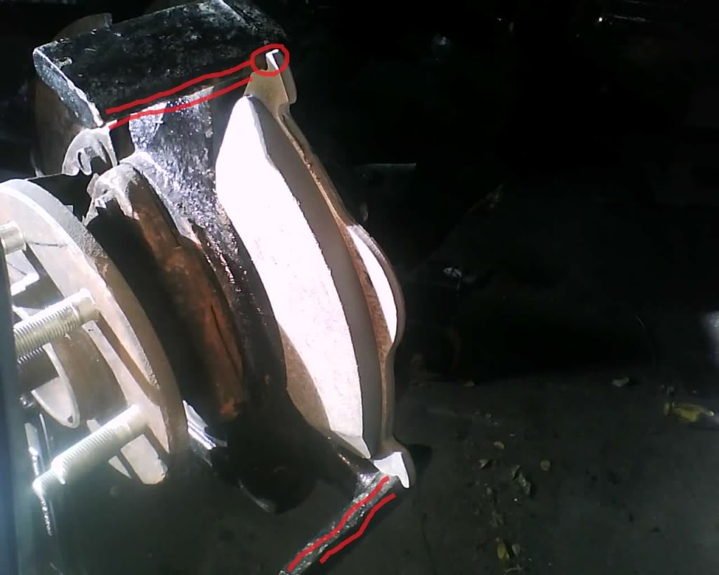
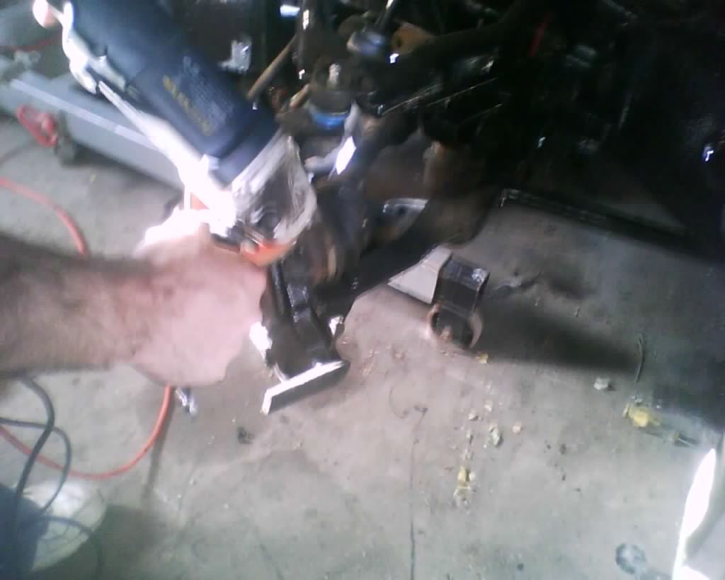
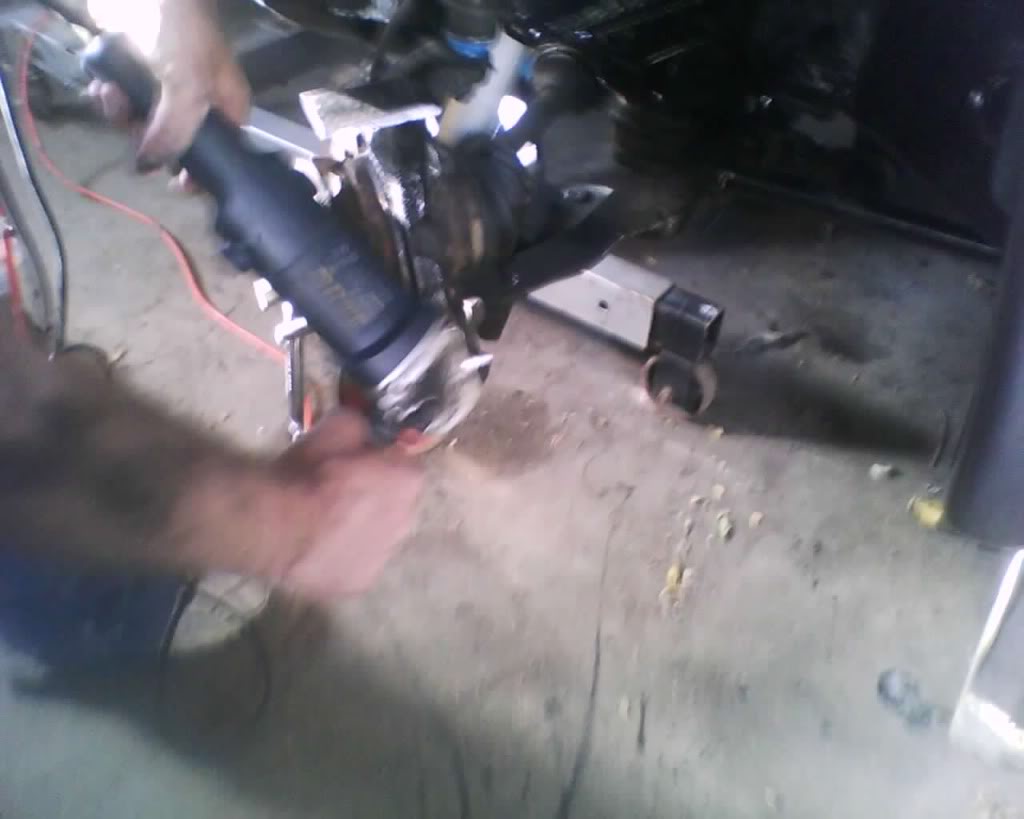
Mine was uneven so i smoothed them out with a grinder.
pic
pic
More to come and will update with pics.
pic
I am posting them and will edit each later.. just have some time to kill right now and wanted to get started on this.
The following guide is MY way in doing this and is done at at YOUR own risk. I am not responsible if you have something go wrong. This information should be used along with a service manual and always stay within your skill level, don't go tearing down the transmission if your only experience is changing the brakes another words. Start off slow and gain skills and knowledge to expand you abilities
Tools needed
7mm Hex
lug wrench
screwdriver
C clamp
loosen lug nuts
Jack up and secure truck with jack stand
remove lug nuts and tire
loosen the two hex bolts on the back of the brake caliper using a 7mm hex.
pic
top one
pic
bottom one
pic
Now wiggle the caliper off (you may have to pull out on the blots you just loosened in order for it to clear the holes) and you have this
pic
Remove the pads
pic
open the master cylinder to release pressure when pushing the piston back in,
pic
Grab a C clamp and slowly squeeze the piston all the way back in like so
I should add here that the proper way to do this is to remove the brake line from the caliper and push the piston back in pushing the fluid out threw the hole in the caliper where the brake line goes in. this would be the proper way. the way I did it is MY way and carries a risk u may damage the master cylinder doing. ( i will post simulated pics of the correct way upon installation
pic
I should note do NOT buy anything made in china if you can help it (talking about my c clamp) I actually remember this day and looked for an American made clamp and was not able to.. was not going to drive 20 miles to indy to sears to get one.
pic
Okay if your here why not make this caliper look better? if you do then here is how.
about $20 for this kit
Follow instruction like so (mask if you want to but if you careful not needed)
pic
Clean REALLY good, this is the key to getting a good look and making the paint stick well
pic
Paint
pic
finished with painting the calipers
pic
okay back to the reinstall of the brakes
you will want to check where the pad touches for uneven spots, if you find some then you will want to grind the spots here marked in red to make them even and smooth.
pic
Mine was uneven so i smoothed them out with a grinder.
pic
pic
More to come and will update with pics.
pic
Last edited by schusterjo; 09-19-2009 at 06:22 PM.
#32
09-05-2009, 01:29 PM
The following guide is MY way in doing this and is done at at YOUR own risk. I am not responsible if you have something go wrong. This information should be used along with a service manual and always stay within your skill level, don't go tearing down the transmission if your only experience is changing the brakes another words. Start off slow and gain skills and knowledge to expand you abilities
Tools
Lug wrench
7/8 wrench or socket
9/16 wrench (to loosen inner jam nut)
pliers
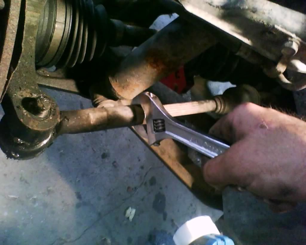
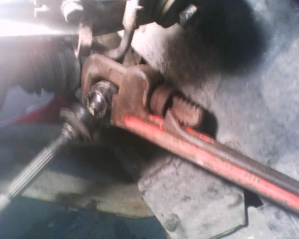
I did not have a wrench big enough for inner tie rod so I used a pipe wrench or you could use a large crescent wrench
as always loosens lug nuts
jack and secure with jack stands
take wheel off
First mark jam nut location with white out or some type of fast dring paint. (this is really great if you are just replacing outer but not so much if replacing both inner and outer, it still will give you an approx length if replacing both.
pic
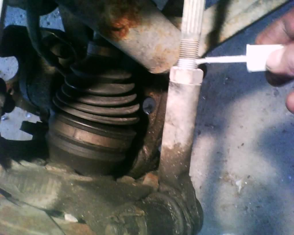
now loosen jam nut
pic
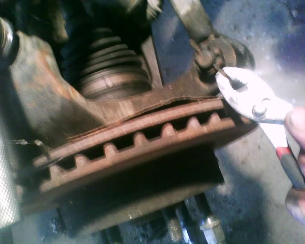
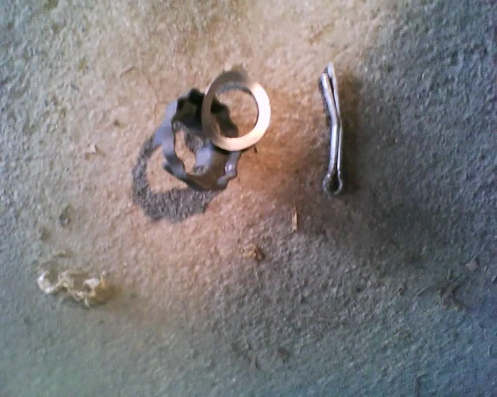
remove cotter pin
pic
remove top nut
pic
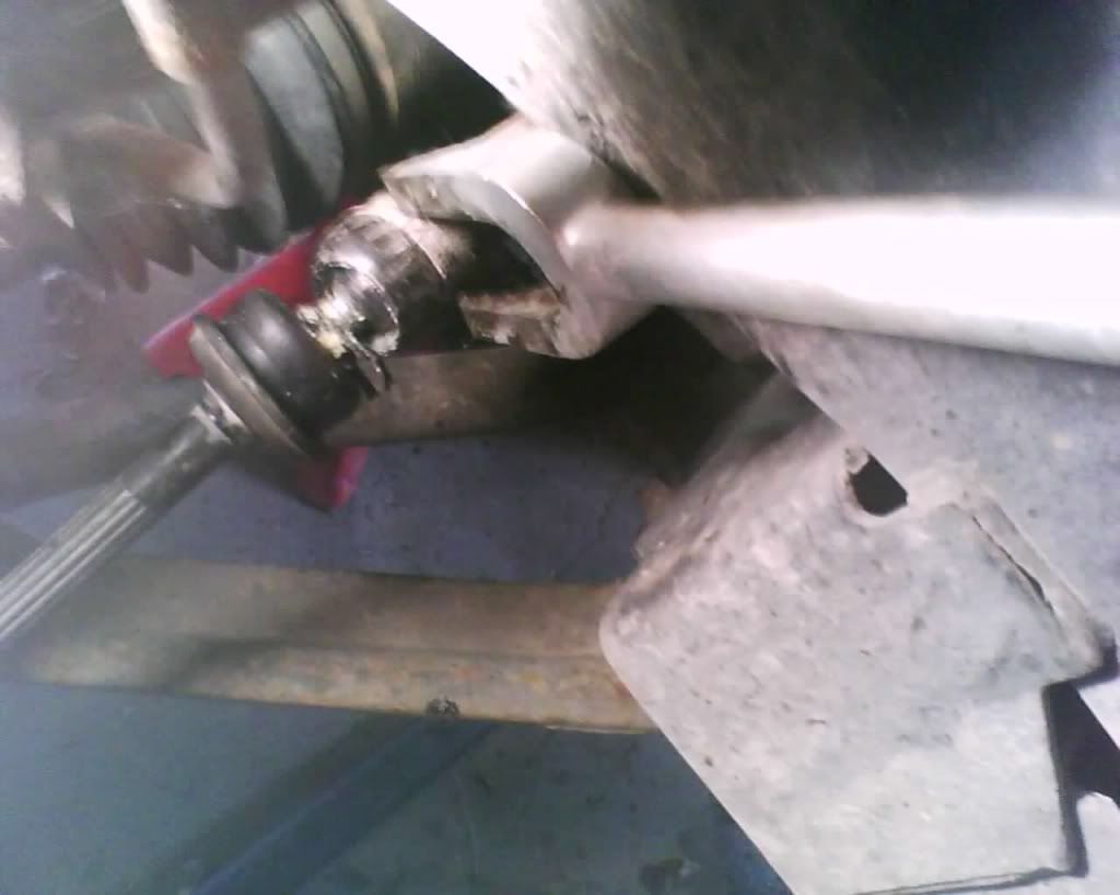
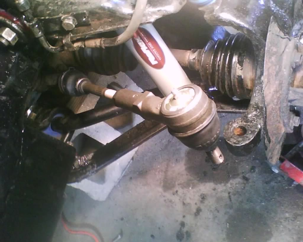
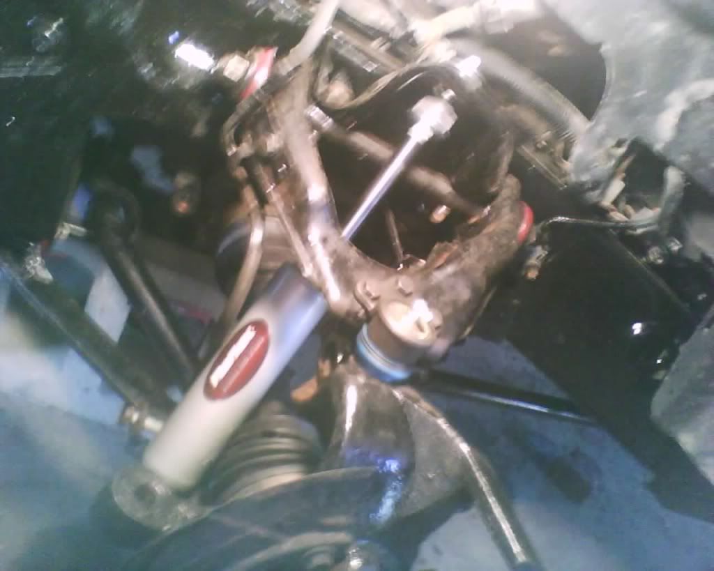
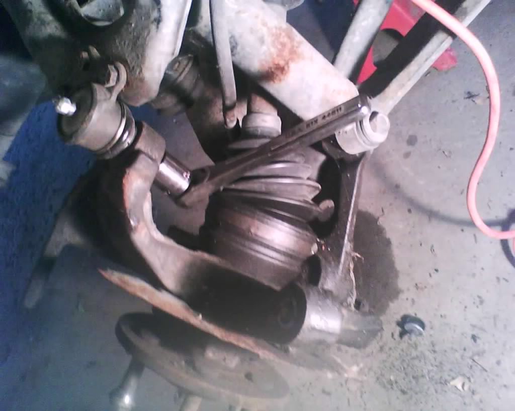
separate the tie rod, pickle bar is great if you are replacing the tie rod not so if you are going to re-use the tie rod, you have to be VERY careful with a pickle bar not to rip the boot, can always use a tie rod separate tool if you going to reuse it or be super careful.
pic
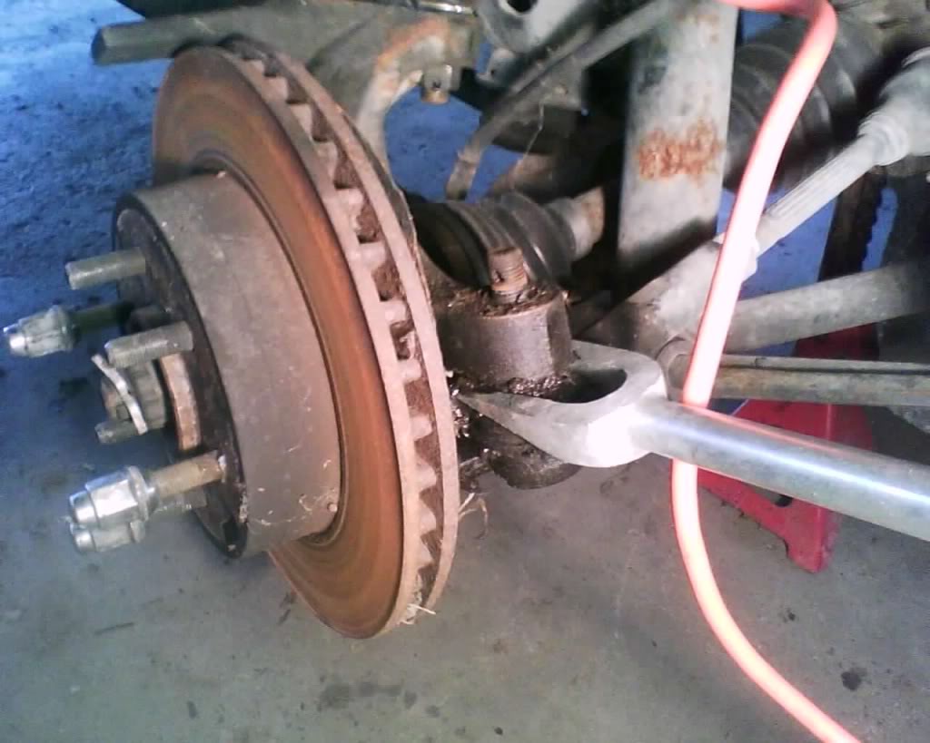
smack it pretty good to get it to separate
pic
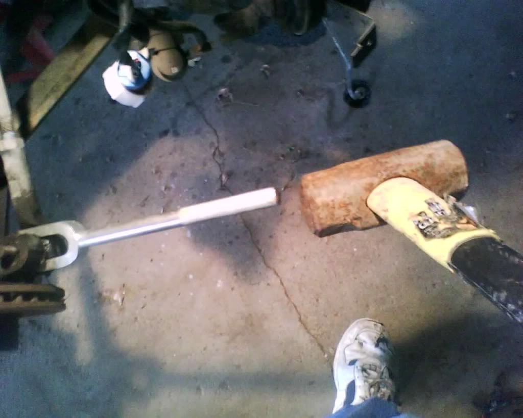
pic
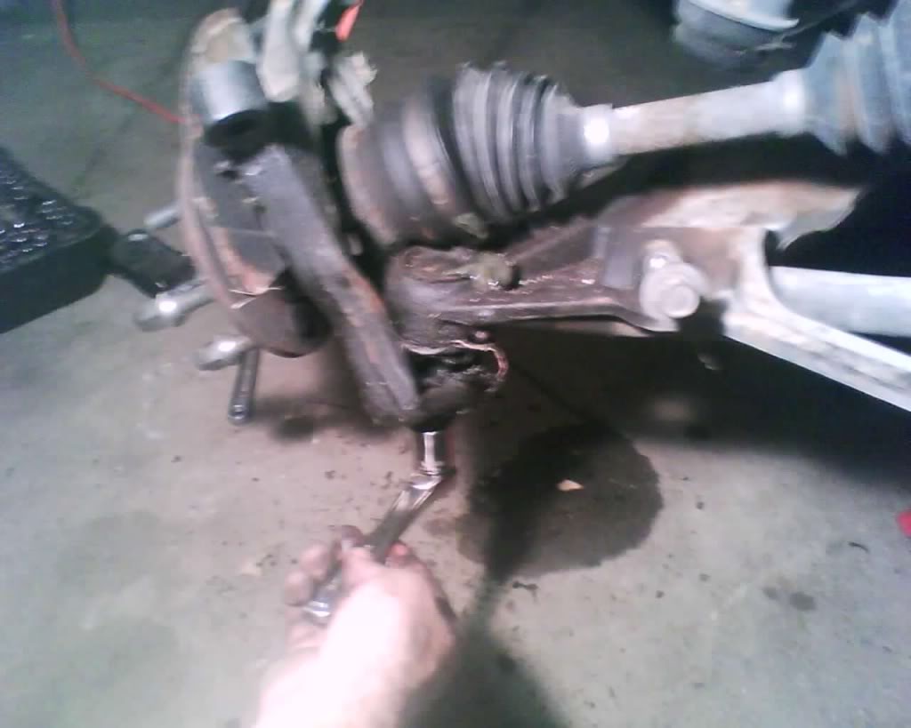
The inner you need to pull the boot back (I used the pickle bar to pry it back)
pic
Remove it like so
pic
Now moving on to the reinstall
First apply the lock tight that comes with the new tie rod
pic
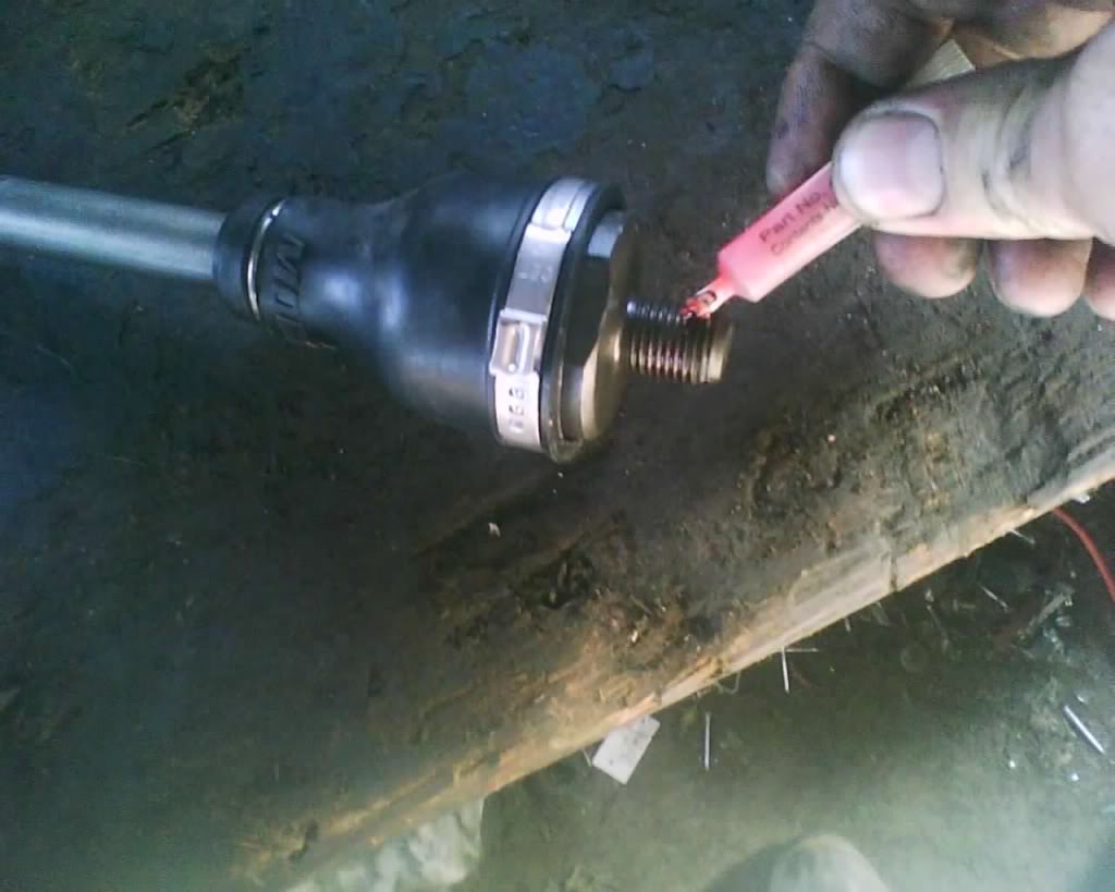
Now you just twist it in as tight as you can get it
pic
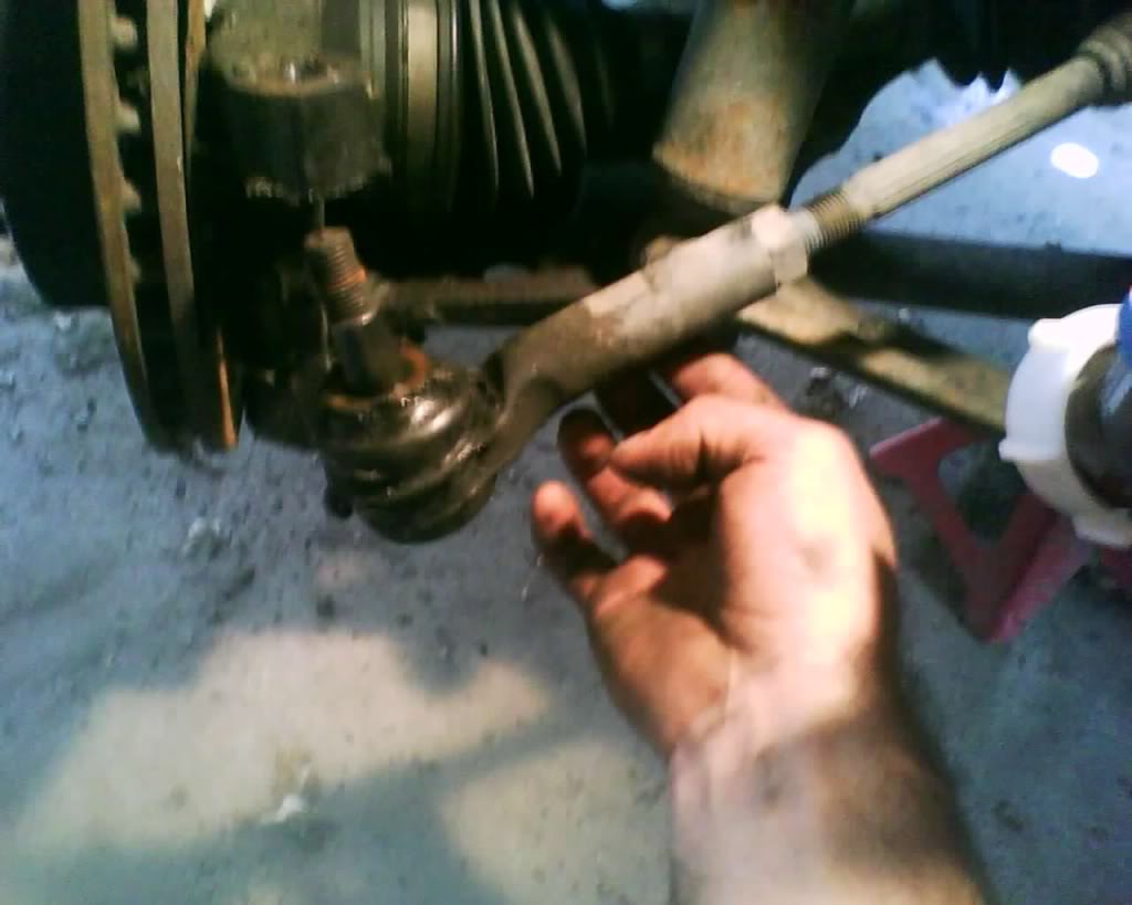
Screw on the jam nut and take the old tie rod and compare the length and match up the placement of the jam nut.
pic
Now screw on the new tie rod end, if just replacing the outer screw it all the way up to the point where you applied the white out/paint earlier
pic
More to come
pic

Last edited by schusterjo; 09-07-2009 at 09:23 AM.
#33
09-05-2009, 03:03 PM
The following guide is MY way in doing this and is done at at YOUR own risk. I am not responsible if you have something go wrong. This information should be used along with a service manual and always stay within your skill level, don't go tearing down the transmission if your only experience is changing the brakes another words. Start off slow and gain skills and knowledge to expand you abilities
Tools
lug wrench
9/16 socket
1" socket
1 1/2" socket or 32MM
1/socket
15mm socket
13mm socket
18mm socket
7/8 socket
3/4 socket deep well
13/16 socket
if i missed something let me know and i will add it.. some of these may not be exact but they worked for me.
Okay if you are just removing the top control arm you do not need to loosen the axle or axle nut
loosen the axle inner nuts (do this before you jack up the truck or the tire will spin, don't take them all the way off just loosen)
pic

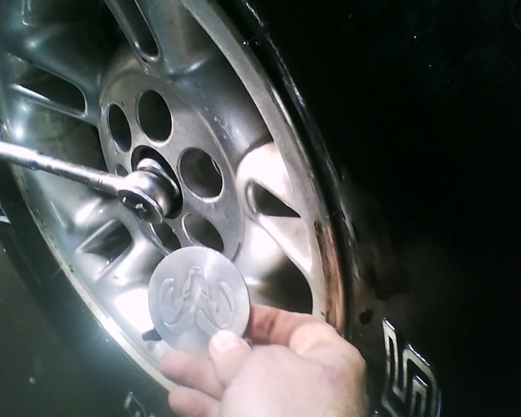
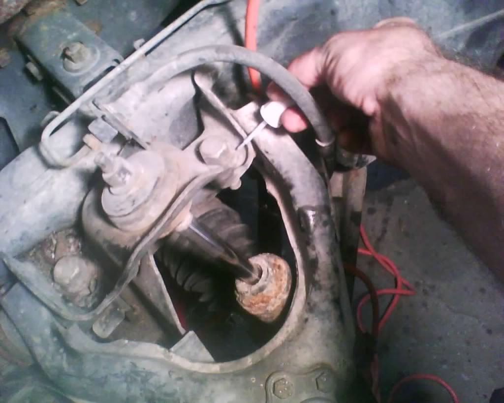
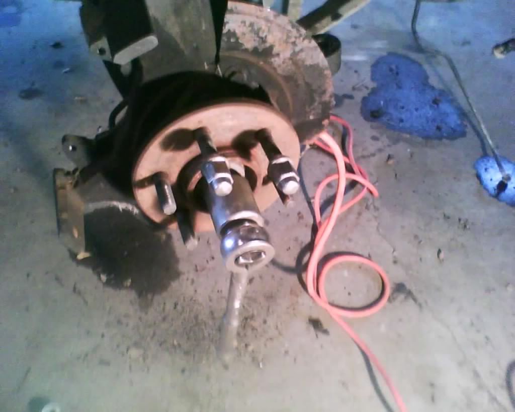
Next loosen the axle nut by removing the center cap on the rim (do this before you jack the truck up or tire will spin)
pull these off first to gain access to the axle nut
pic
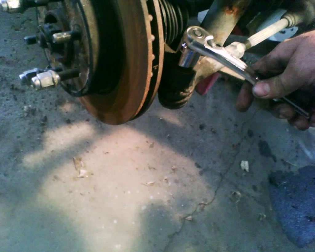
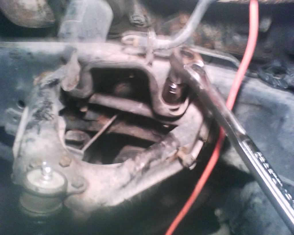
then loosen it
pic
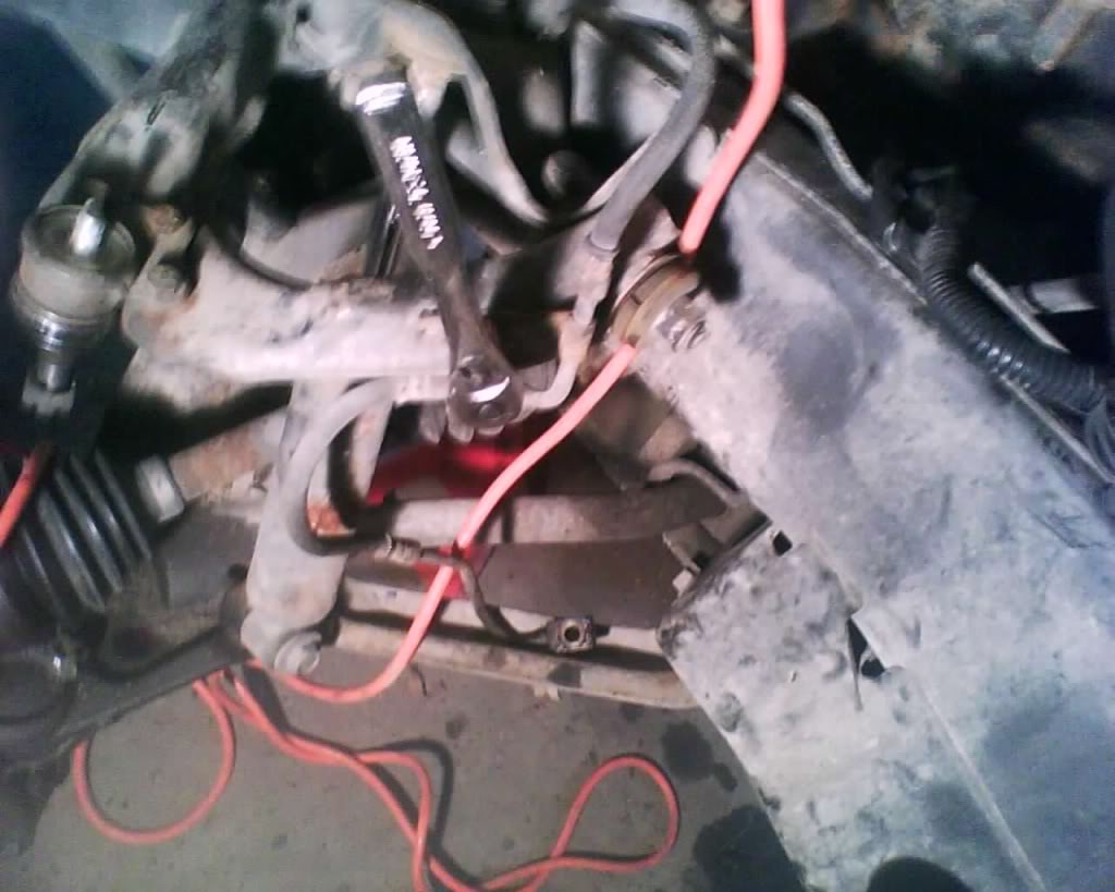
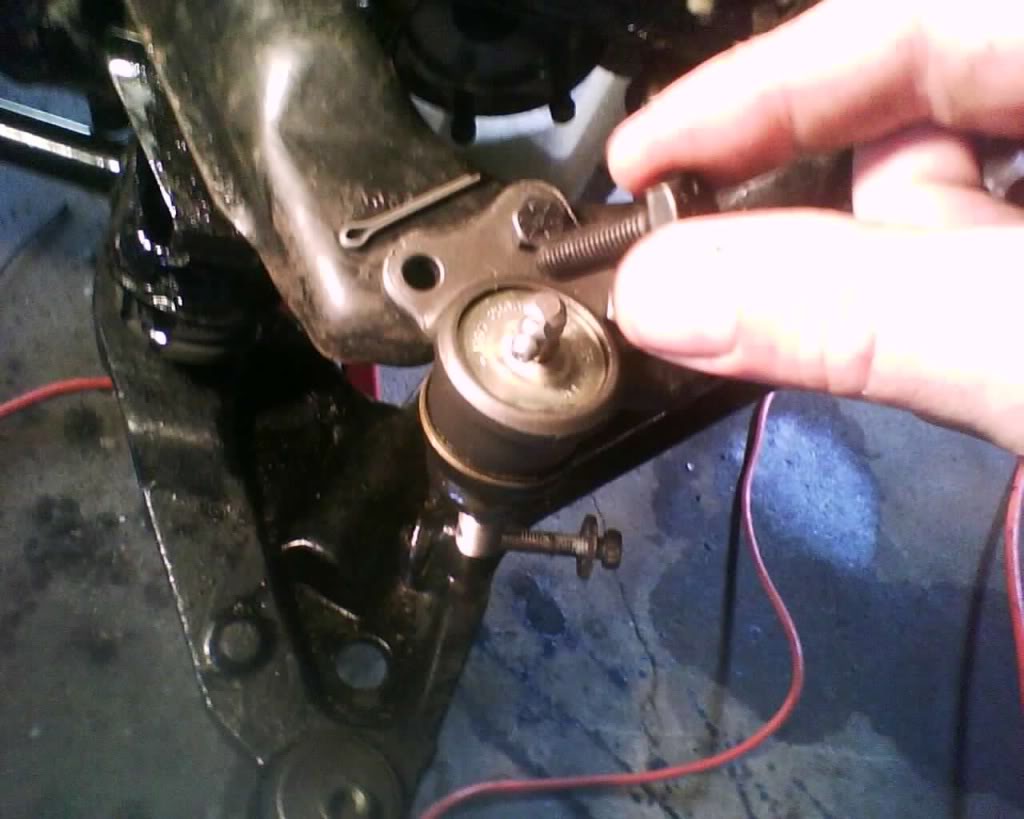
loosen the ball joint by removing cotter pin and remove the nut
pic

Using a pickle for smack it real good to separate (pickle fork works well but if u plan on reusing the ball joint pickle fork has a VERY good chance in tearing the ball joint boot, use a ***** joint separating tool you can rent from Autozone or Advance auto if you plan on reusing.)
pic
Now mark the control arm bolts to note their location
pic
remove brake line
pic
Now loosen the control arm
pic
Lower control arm
loosen axle outer nut
pic
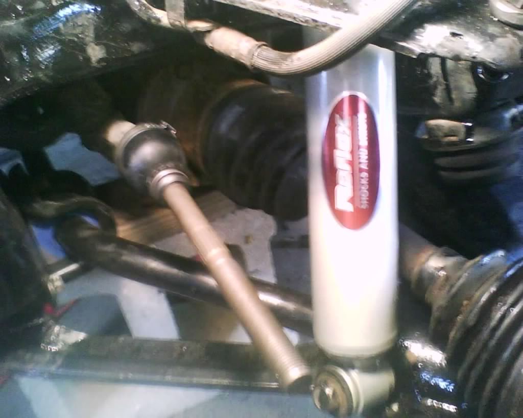
Remove shock (this is the new shock cause i can't find the pic of me removing it but very simple, just unbolt it top and bottom nothing special here.
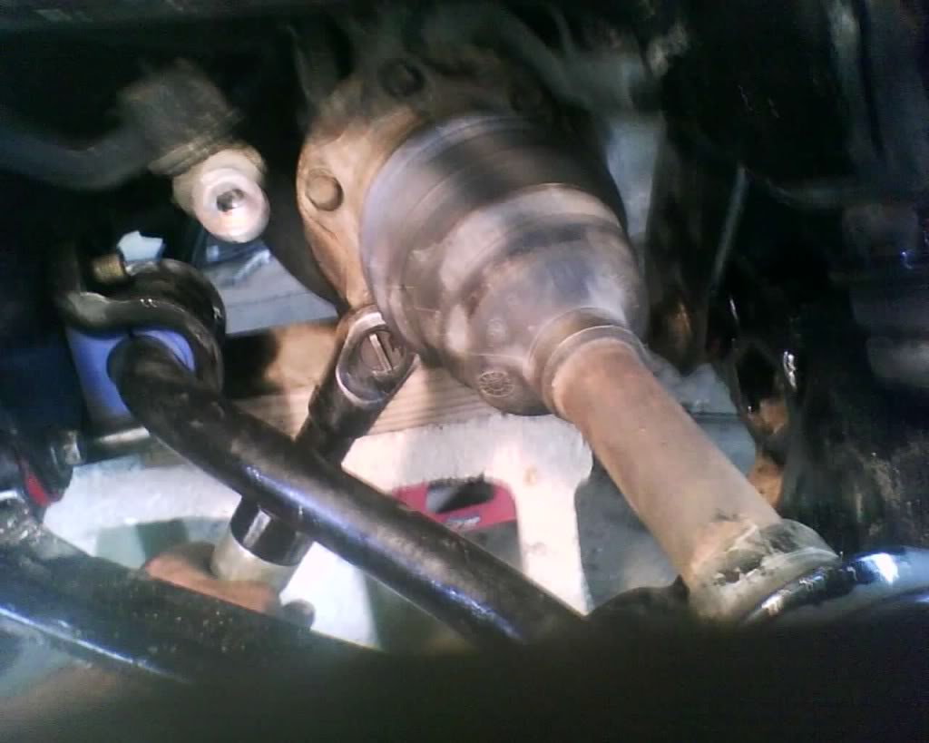
You should remove the axle at this point by removing the inner bolts u loosened before
(i did not but you should)
pic
pic
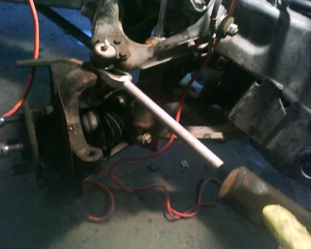
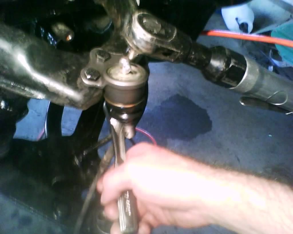
Now remove separate the lower ball joint by removing the cotter pin and nut then use a separating tool such as a pickle fork
pic
pic
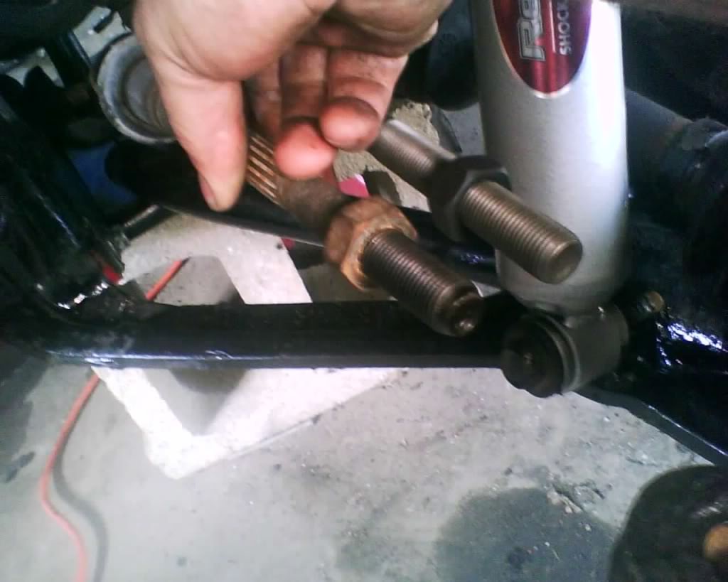
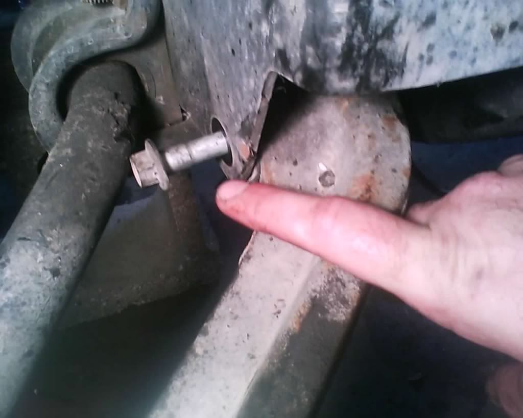
Remove torsion bar, mark the torsion bar and then remove (like you would the tie rod jam nut in a way or how you did the upper control arm bolts, this way you known how the parts were when you reinstall) mark both ends
pic
pic
pic
Remove the cap in the frame to access the nut
pic
pic
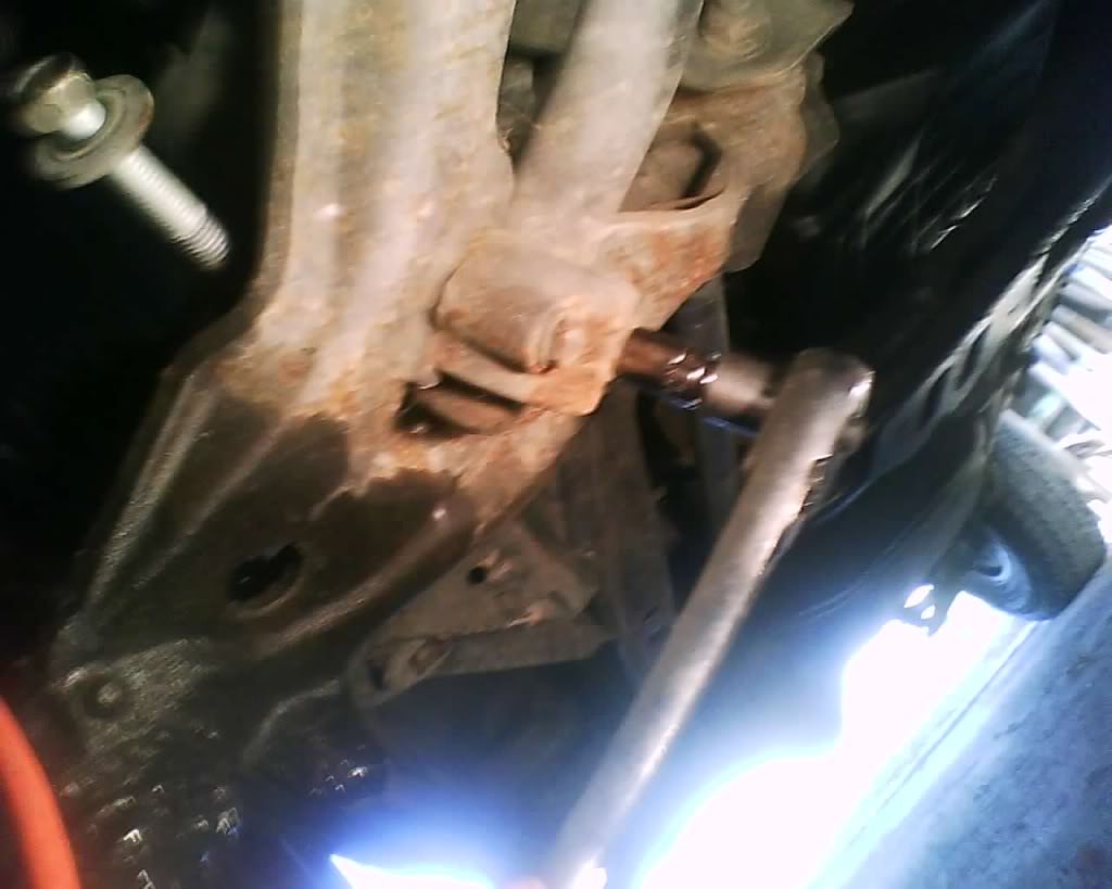
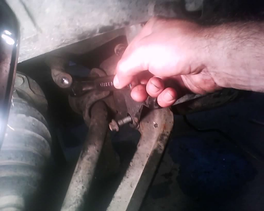
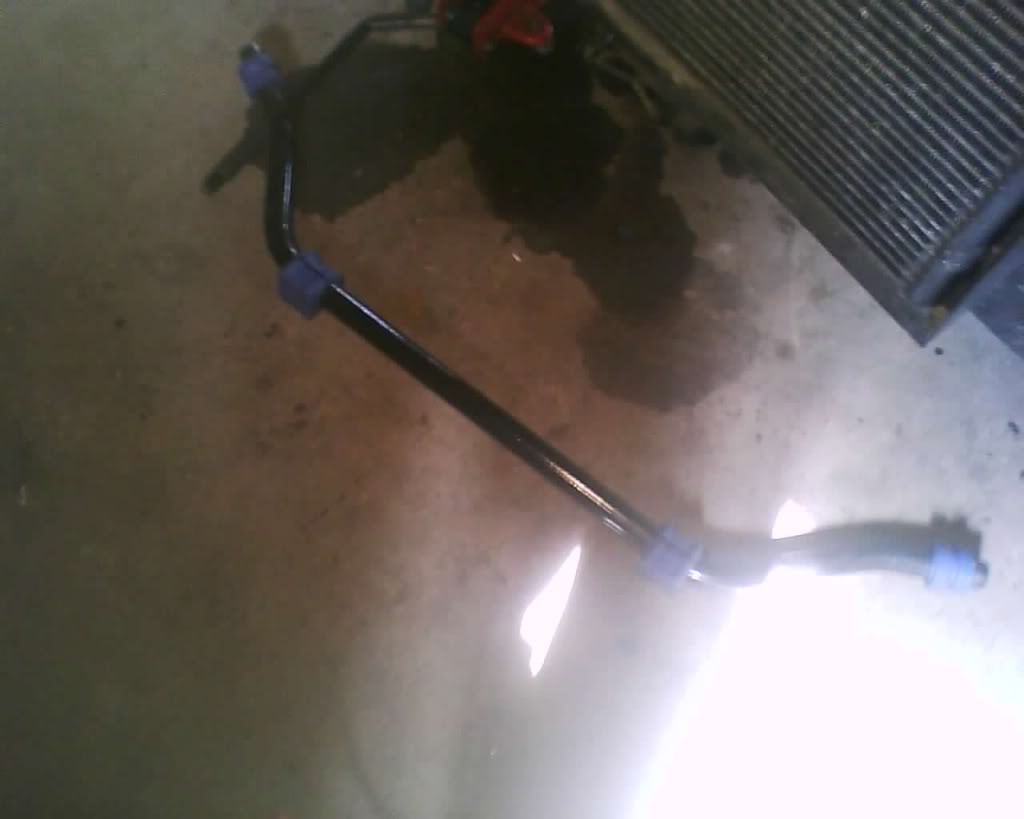
the front you will need to loosen or remove the sway bar
pic
now remove the rear and wiggle the control arm off
pic
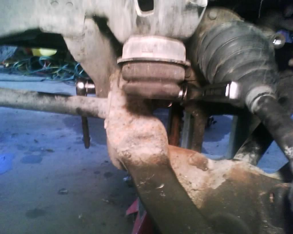
pic

Last edited by schusterjo; 09-08-2009 at 10:44 PM.
#34
09-05-2009, 04:28 PM
The following guide is MY way in doing this and is done at at YOUR own risk. I am not responsible if you have something go wrong. This information should be used along with a service manual and always stay within your skill level, don't go tearing down the transmission if your only experience is changing the brakes another words. Start off slow and gain skills and knowledge to expand you abilities
if you are replacing bushings you probably are replacing ball joints as well
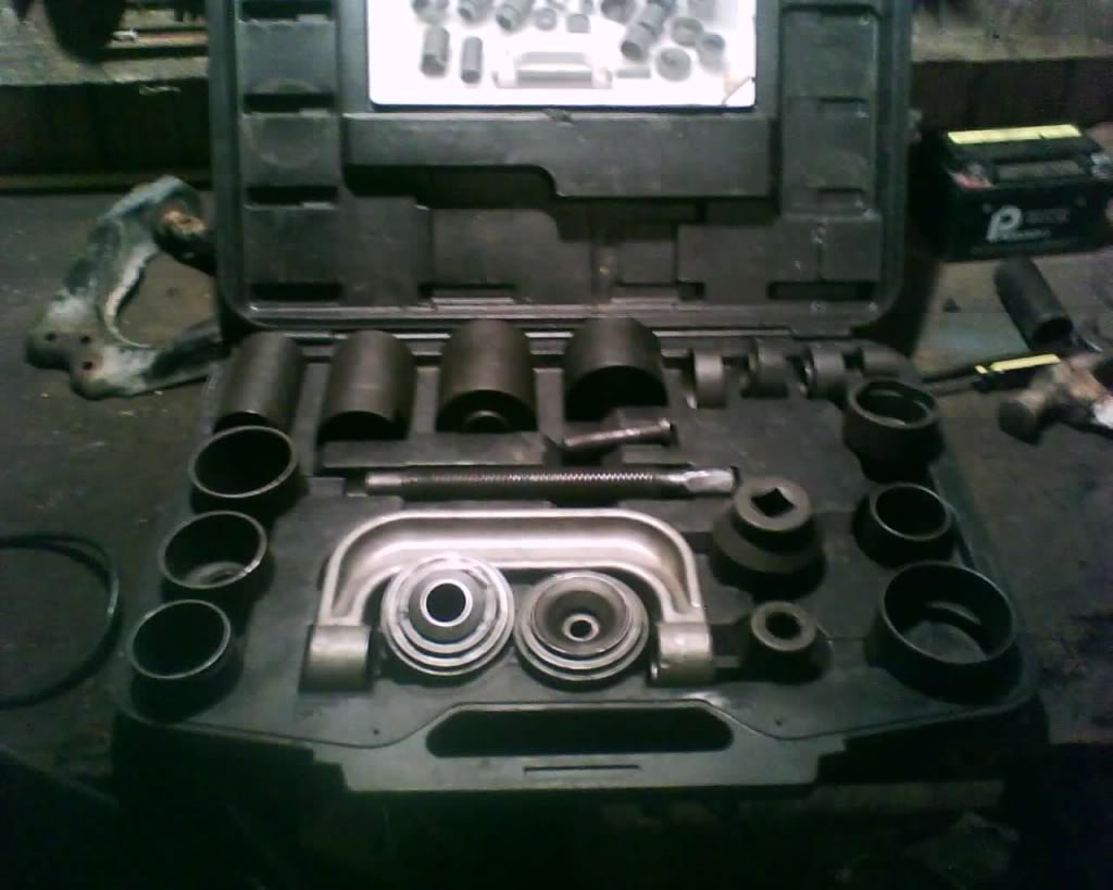
Anyhow I used a ball joint press tool to do the bottom and no way I could of done this at home without it that i know of... Rented this tool for $155 at Advance auto (well i know the guy and he let me use it for free)
You will want one just like this, it has all the tools to make this an easy job, does take a little time though.
first the tool
pic
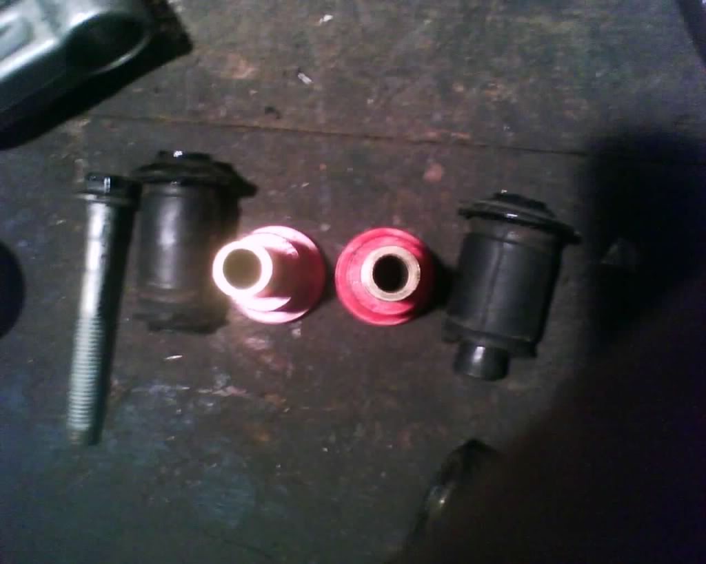
Now I dunno why but energy suspension placed the wrong center pieces in the bushing (got to love that quality low cost labor they use) It did take me a few minutes to figure out what the heck was going on but you do not want to start the install till you get this strait.
the bushings come in 2 different size diameters with 2 different size diameter centers for the two different size bolts that are used to hold the control arm on.
So, just go by this, Big bolt goes in smaller diameter bushing, place the larger diameter center brass tube into the smaller diameter bushing (rear control arm bushing)
pic
here we go,
remove the outer edge of the bushing like so
pic
pic
you can burn it out with a torch or drill it out like i did.. if you use a drill just make a hole, then go to the other side and make a hole, then goto the top and make a hole, then goto the bottom and make a hole, then make a hole in between the holes you just made and so on.. eventually you will be able to start prying out rubber chunks.. this part kinda sucks and does take time. approx 30 min each but if ya don't have a torch this is your option (well the only one i know of)
pic
pulling chunks
pic
now you have to split open then center piece of the bushing, it will already have a cut all the way down u just need to open it up.
pic
Then you have to pry it away from the end use a hammer to hit the screw driver pry it away
pic
Pull it out
pic
Now take the super lube provided in the bushing kit and apply it to the bushing, I simply applied it to the outer end of the bushing (cause its just going to push it down as you push it in) I did not have to use ALOT of lube like others have said.
get the bushing started like so
pic
Then if you have it lubed decent just crank it in and it will go in pretty easy (I did not have the ball joint press when i did this but i did do one upper with it and yes you can use it and it works well,)
pic
Done with upper and looking good
pic
Lower
Well I have heard people cry and cry about the lower and I just don't see why. For me it was way better then the upper... I used the balll joint press and it was pretty fast..
Here we go
You WILL want to cut the ends off just as the top
(reminder here)
pic
pic
Okay you get that end off and now press it threw with the ball joint remover (you leave the end on and it makes it pretty tight with that extra width being pushed threw, so remove it)
30 sec and its out
pic
Now to put it in just do it like so (use a little super lube)
pic
the hardest thing about the bottom was just find the correct combination of extractors ext... to use with the press... but if you look at my pic you should be able to see what ones to use...
Thats it you now have new bushings
Last edited by schusterjo; 09-07-2009 at 09:29 AM.
#35
09-05-2009, 04:44 PM
The following guide is MY way in doing this and is done at at YOUR own risk. I am not responsible if you have something go wrong. This information should be used along with a service manual and always stay within your skill level, don't go tearing down the transmission if your only experience is changing the brakes another words. Start off slow and gain skills and knowledge to expand you abilities
Tools
pickle bar
hammer
13mm 18mm 21mm (13/16)
17mm wrench
1/2 socket
maybe need
angle grinder and a center punch
lower add these
1 1/4" or 32 mm socket
Ball joint kit
9/16 socket
15mm socket
3/4 socket
snap ring tool
1" for torsion bar
Upper
Okay loosen lugs jack up and secure with jack stands
take wheel off
Remove brake line (i don't but its a good ideal) like so
pic
Remove brake caliper and rotor
Remove the cotter pin by cutting off the loop and pulling the ends threw
Loosen the nut (u can take it all the way off or just leave it on barley tight so the control arm may not fall all the way down when separating)
pic
separate with pickle fork
pic

if you still have a ball joint with rivets you will need to grind them off and punch them out, if not then remove the three bolts holding the ball joint on
pic
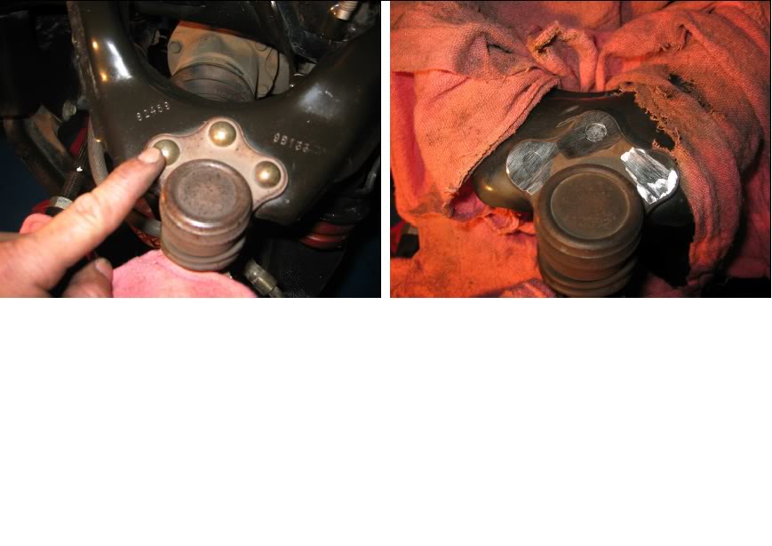
pic
install new one like so, tighten to spec 25
ft-lbs.
pic
Lower
Okay I took my control arms all the way off but i will try to explain how to do it without taking the control arm off,
loosen the inner axle shaft do not take all the way off just loosen at this point
9/16
pic
Now loosen the outer axle hub
1 1/4, 32mm
loosen lug nuts, jack up support, with jack stand and remove the tires
Remove the brakes (follow brake guide in this thread)
remove upper ball joint
Remove the axle now..
This will give you plenty of room to press out the ball joint
If you do not have goto Autozone or Advance Auto and rent this set.. You want one just like this with plenty of tools to configure your setup, the smaller kits just don't have what u need and require other means in getting the ball joint all the way in, such as lowering your truck onto a block with a socket fitting over the ball joint bolt (but not larger then the ball joint) to use the wight of the truck to push it in. this could lead to damage if your not cautious.. This kit will allow for you not have to do that.
pic

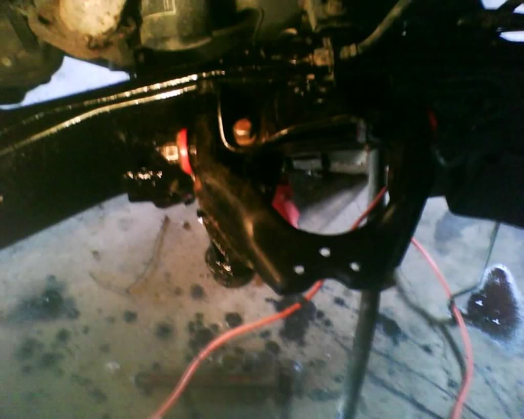
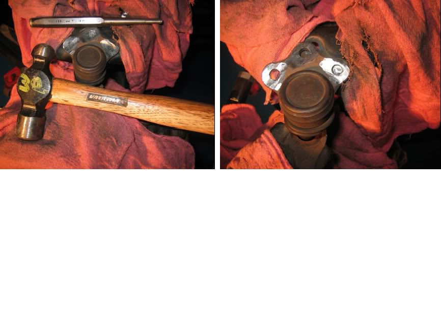
Now if your ball joint has a snap ring on top remove it or if it has the 4 little stub things hit them with a hammer and bend them back.
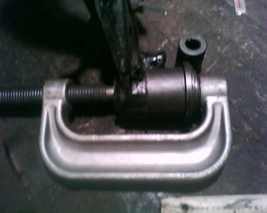
pic
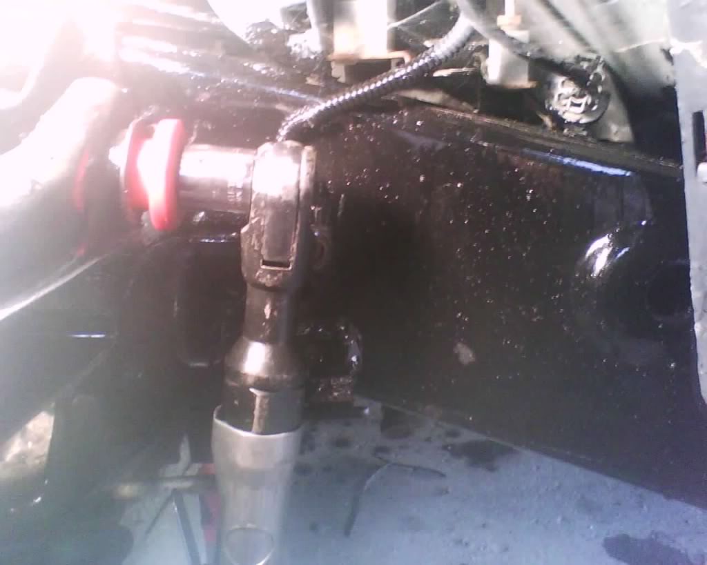
Now to use the ball joint press you always put the bolt stud on the balljoint into the hole end of the large C clamp like so
pic
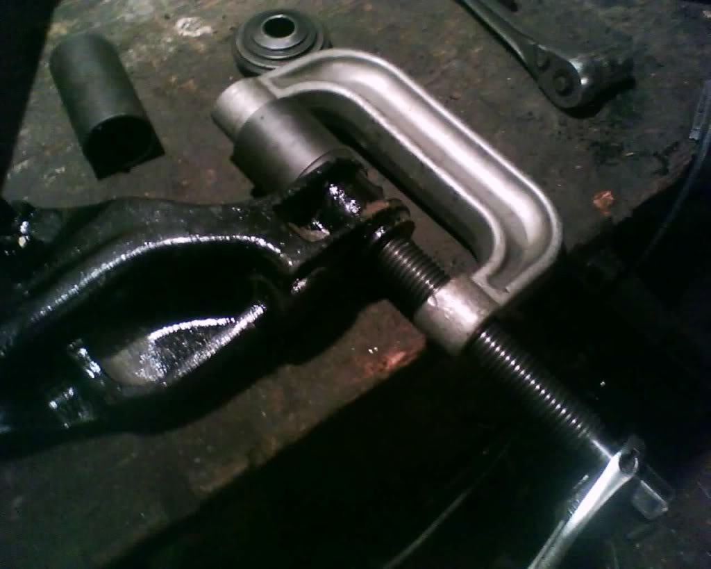
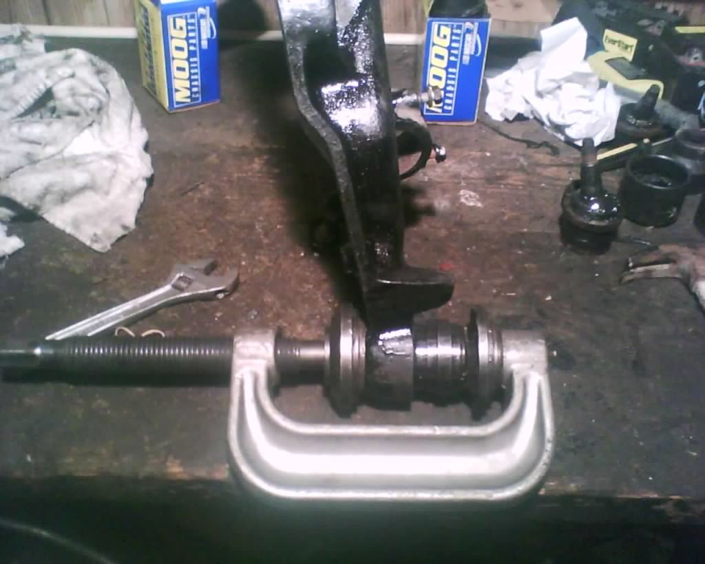
To make it go out set it up like this (you will want to find the socket just a bit larger then the ball joint with the large hole at the end (receiver) you will not be able to get it all the way out with the socket but gets it really close where a few taps with a hammer and a socket drops it right out)
pic
http://s289.photobucket.com/albums/l...moverlower.jpg
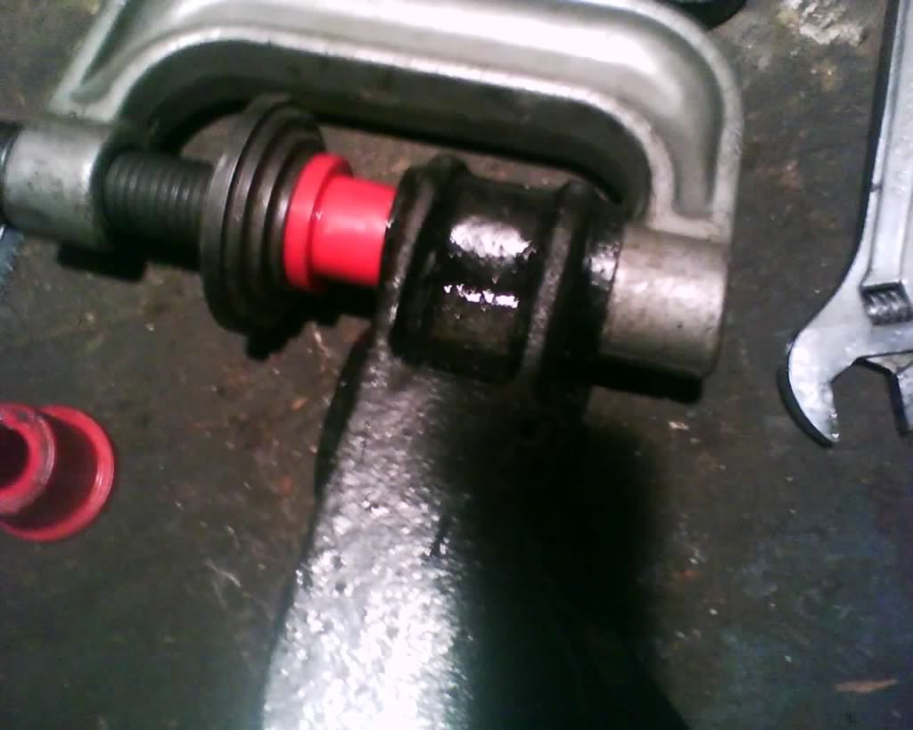
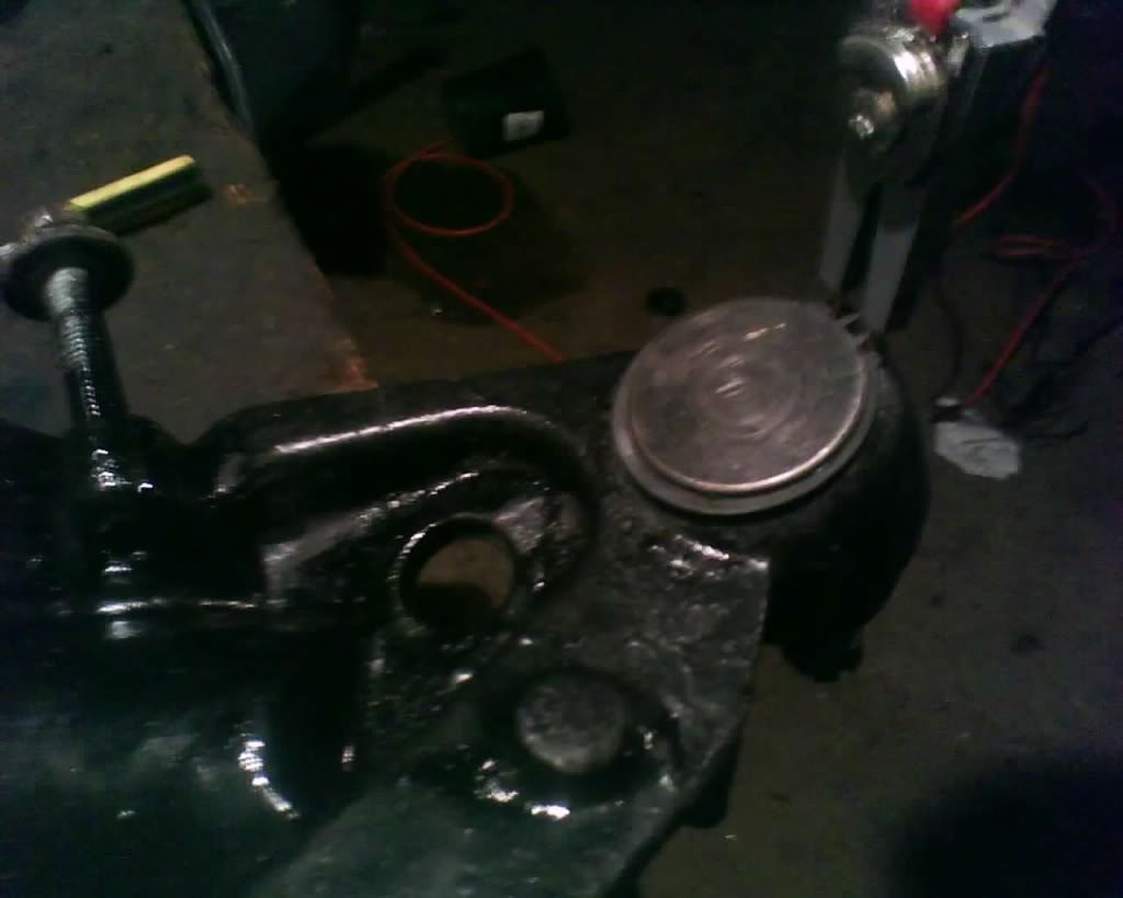
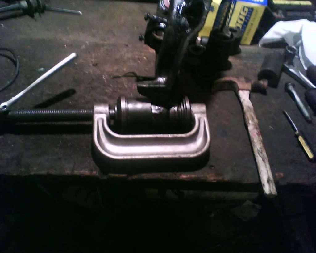
once out push the new one in like so
pic
You will only get it flush with this setup (you can't use a deeper one at first because the C clamp is not wide enough to use the deeper one at first, so you have to start with one that is a little shorter, push the ball joint in a far as it will allow you, this gives you more room to now use the deeper receiver socket.
So now we finish it up with this setup
pic
okay now the ball joint is in all the way.. time to install the snap ring
pic
Now when you try to tighten the ball joint nut and it just start to spin on you, jack up the control arm just a little to allow the tapered part of the ball joint to wedge in a little to stop the spin, tighten a little and remove the jack then tighten the rest of the way
Reinstall everything you just took off in reverse order, fill ball joints with grease, torque to specs, take it to alignment shop
Last edited by schusterjo; 09-20-2009 at 10:55 PM.
#36
09-05-2009, 04:45 PM
The following guide is MY way in doing this and is done at at YOUR own risk. I am not responsible if you have something go wrong. This information should be used along with a service manual and always stay within your skill level, don't go tearing down the transmission if your only experience is changing the brakes another words. Start off slow and gain skills and knowledge to expand you abilities
This is pretty strait forward, not going to say easy because it is a pita to get the inner bushing unbolted.. You will need to turn the steering wheel to get the steering parts into the correct position to be able to get a ratchet into the tight area.
first remove the outer control arms
pic
Remove the inner
pic
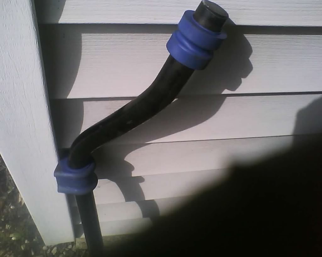
The best option is to use greasable bushing but i chose to just use Moog bushings..
pic
Now go threw the pain and install it lol.. no it is not really that bad but it is a small area to work with on the inners (have worked in much tighter then this so this is not bad at all really)
pic
Torque to spec. Now you may need to jack the control arm up a little in order to get the sway bar to roll in. On the outer there is a groove on the control arm that u must match up to the grove in the bushing, don't have a pic of that but once you see it u will know right away what i am talking about.
Last edited by schusterjo; 09-07-2009 at 08:54 PM.
#37
09-05-2009, 04:46 PM
The following guide is MY way in doing this and is done at at YOUR own risk. I am not responsible if you have something go wrong. This information should be used along with a service manual and always stay within your skill level, don't go tearing down the transmission if your only experience is changing the brakes another words. Start off slow and gain skills and knowledge to expand you abilities
Last edited by schusterjo; 09-06-2009 at 12:44 PM.
#38
09-06-2009, 11:00 AM
The following guide is MY way in doing this and is done at at YOUR own risk. I am not responsible if you have something go wrong. This information should be used along with a service manual and always stay within your skill level, don't go tearing down the transmission if your only experience is changing the brakes another words. Start off slow and gain skills and knowledge to expand you abilities
Okay I had already taken the fan off before i took the pics but it will still do.
I went to auto-zone to rent a clutch fan rental tool. Well they gave me this 5 Piece Fan Clutch Wrench Set .
pic
$55 rental and all money back upon return
Well I found this tool to be worthless and a waste of my time, So I had to make my own.
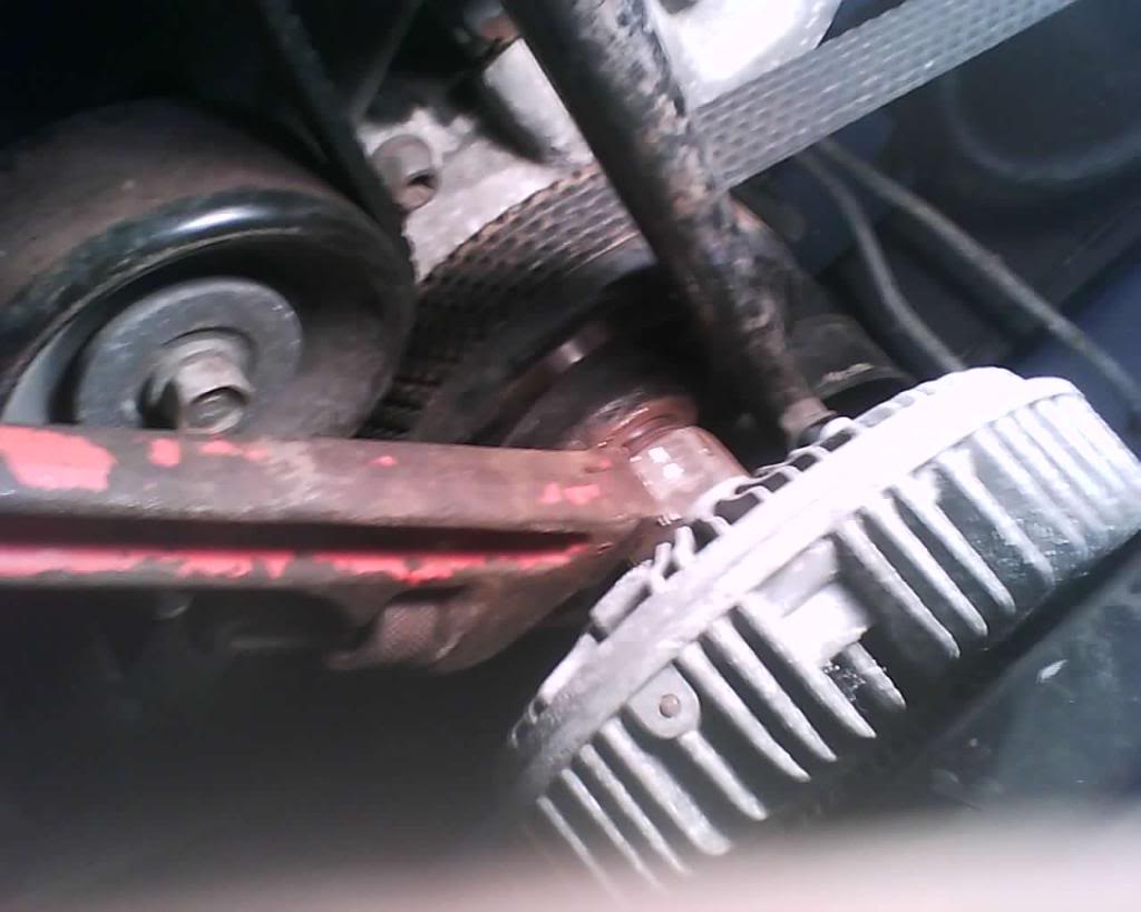
first lets look at this pic.
pic
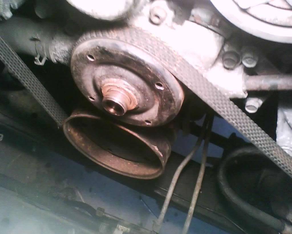
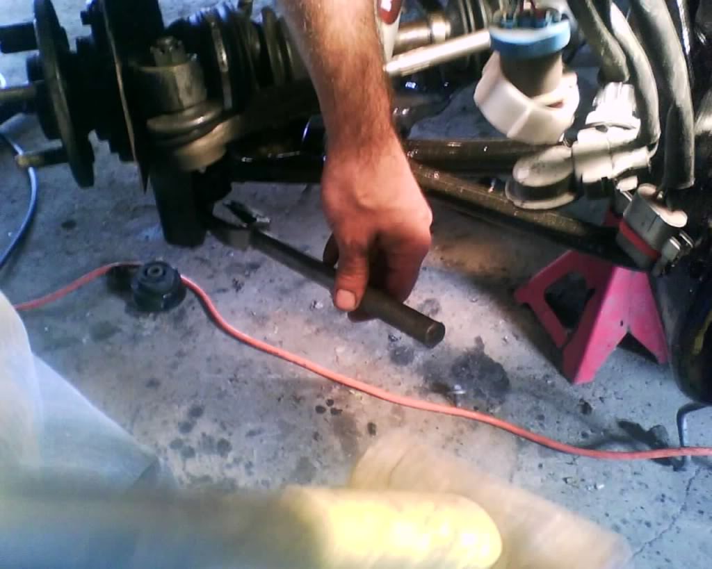
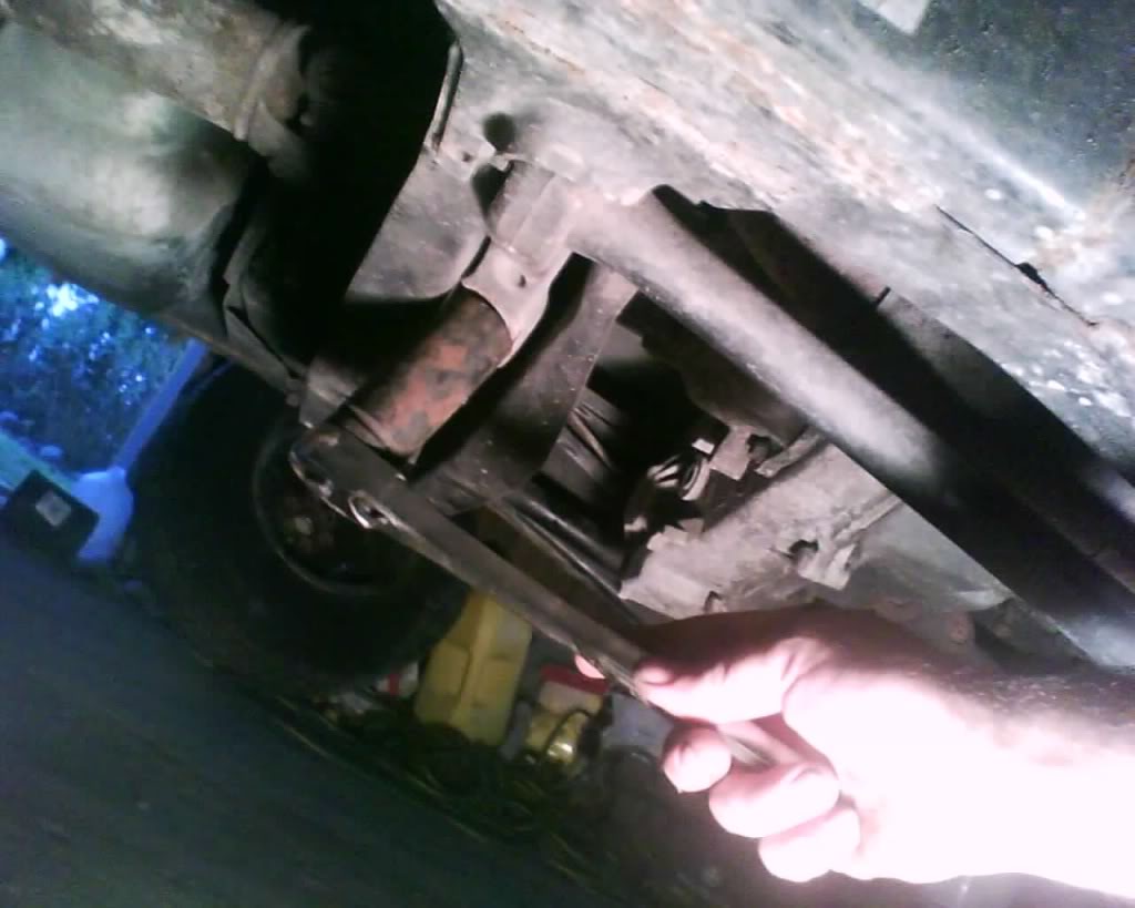
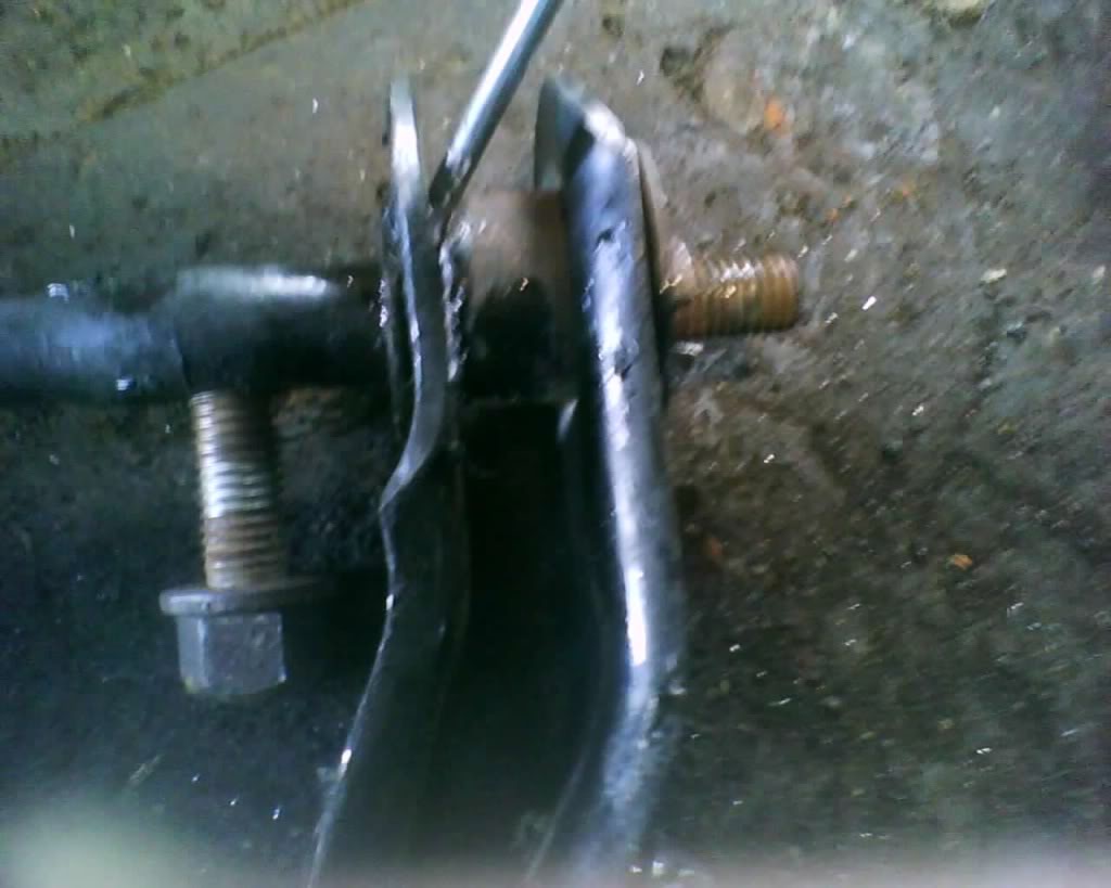
The problem when trying to take the fan/clutch off is the water pump pulley will spin as u turn the nut. So, the holes ar approx 3" apart and this led me to come up with this ideal.
pic
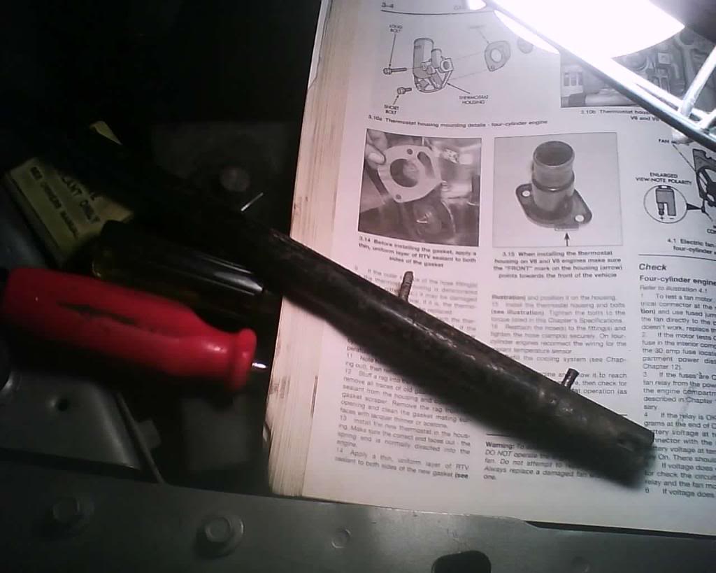
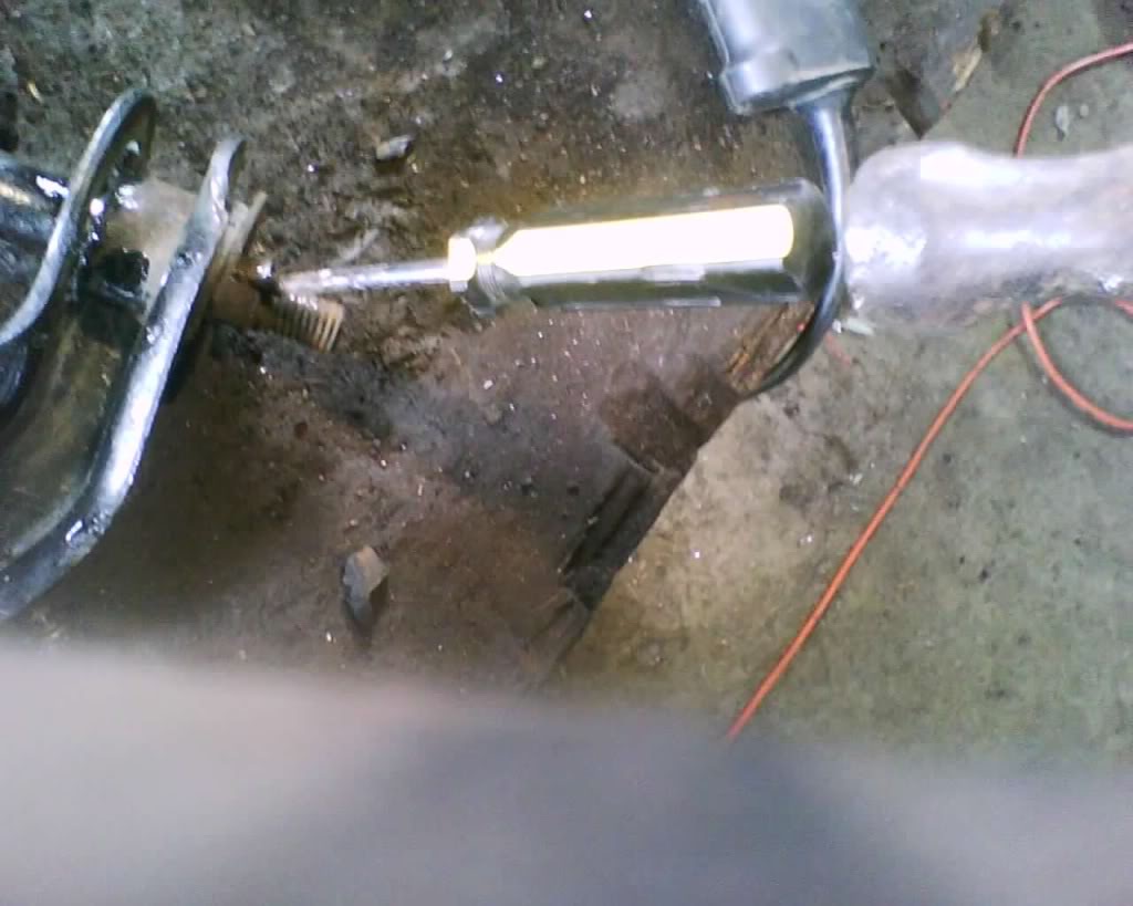
Basically this is a old jack handle that already had the bottom stud on it. Anyhow you just need to find something small that yo can get down in there and be able to drill holes in to place a screw with the head cut off of it..
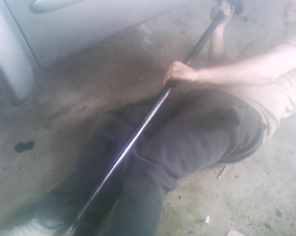
So now we are able to remove it like so and keep the water pump pulley from spinning. I used a pipe wrench but a large crescent wrench or proper size wrench lol will work.
pic
Turn the wrench counter clockwise (right hand threads) while holding the bar with the screws in the holes to keep the water pump pulley from spinning.
Clutch and fan is now off.
Last edited by schusterjo; 09-07-2009 at 09:38 AM.
#39
09-06-2009, 02:24 PM
U Joint Replacement.
This works better if you hit it with PB spray a few days before you remove it.
I am going to list parts here
Precision U-Joints
458 Rear drive shaft this is the one that goes to the rear differential
354 Rear drive shaft this is the one that goes to the front of the rear drive shaft
380 Front drive shaft (4WD) this is the one that goes to the transfer case
369 Front drive shaft (4wd) this is the one that goes to the front differential
above is for 4wd not positive if those top two will work for a 2wd so you will want to check on that.
Tools
3/8 socket or wrench
Hammer
Quality C clamp
screw driver (standard)
pliers
needle nose pliers (don't have to but makes it nice to put snap ring back in)
Two sockets (dunno size but i used a 1 1/2 and the other i dunno to hit with a hammer to push the cap out)
Start by marking both ends so you can put the driveshaft in the same way you took it out. This is very important because if you do not then you may get a vibration and ruin ur new joints.
pic
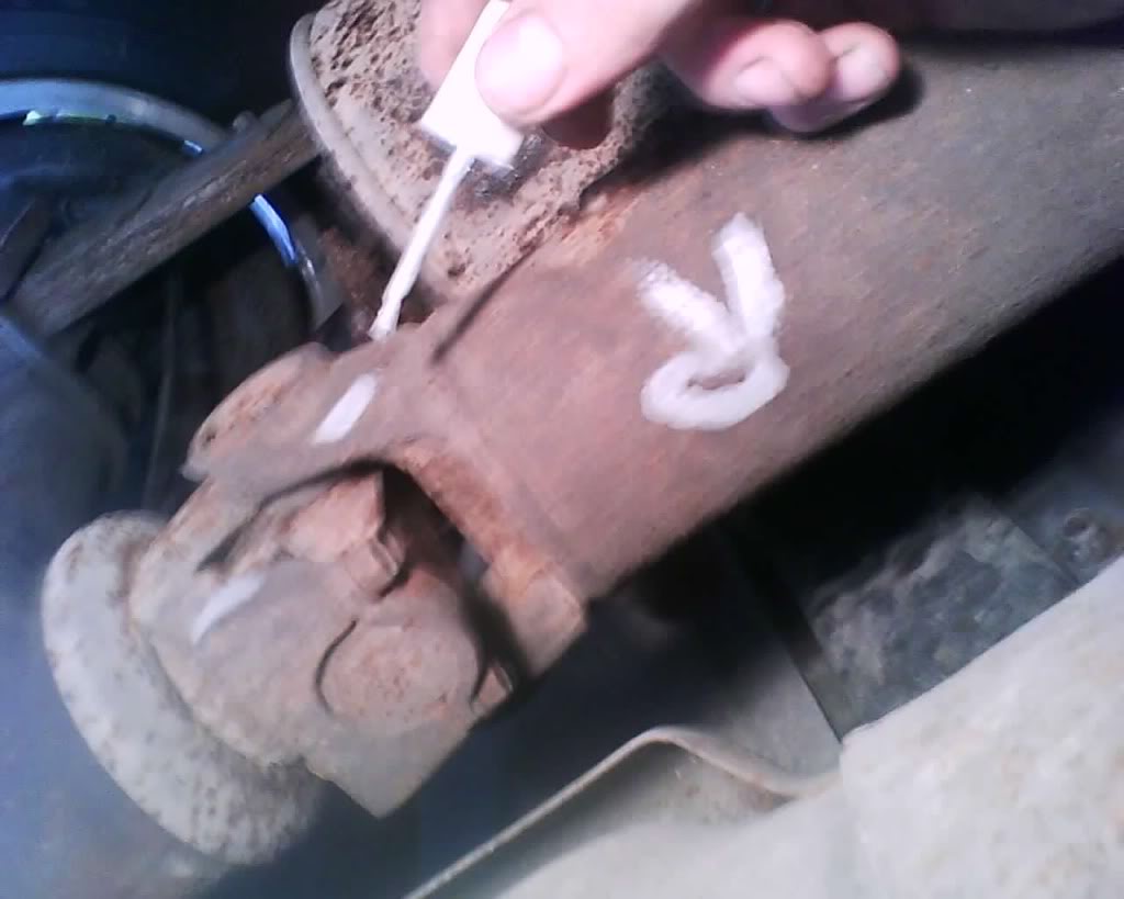
and
pic
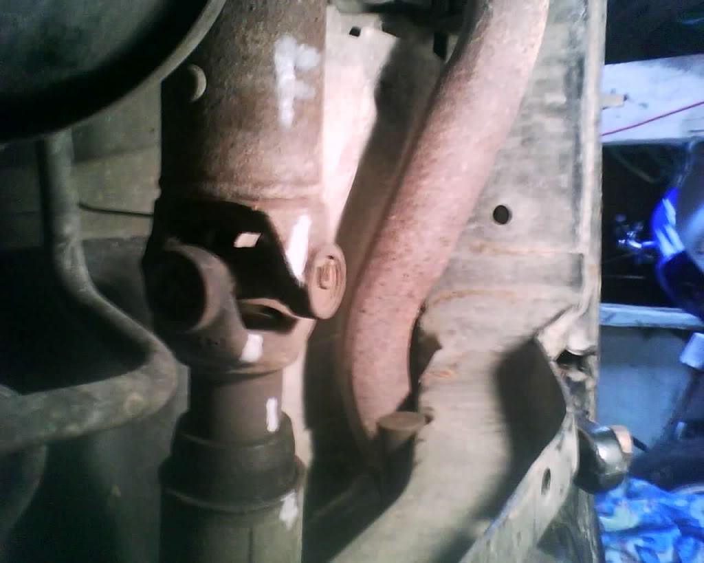
(i put the R and the F on thee to just show you, u do not need to do that unless you want to)
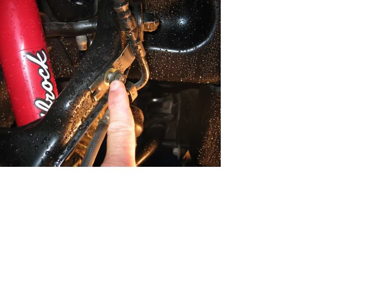
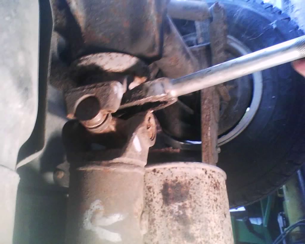
Next remove the rear u bolts/straps on the rear
pic
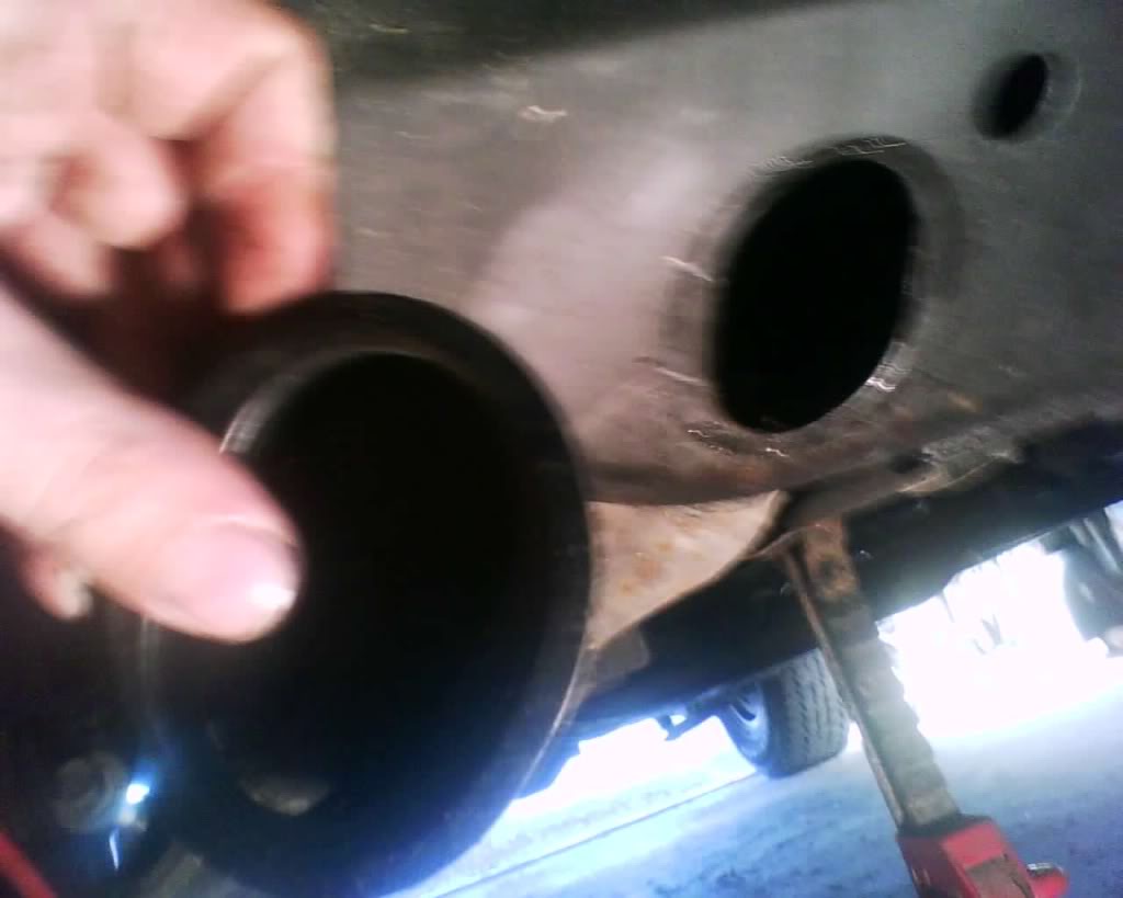
pry on the rear just a little be very careful here not to damage anything... don't let it slam to the ground, once lose from the rear simply pull that shaft from the transmission strait out
pic
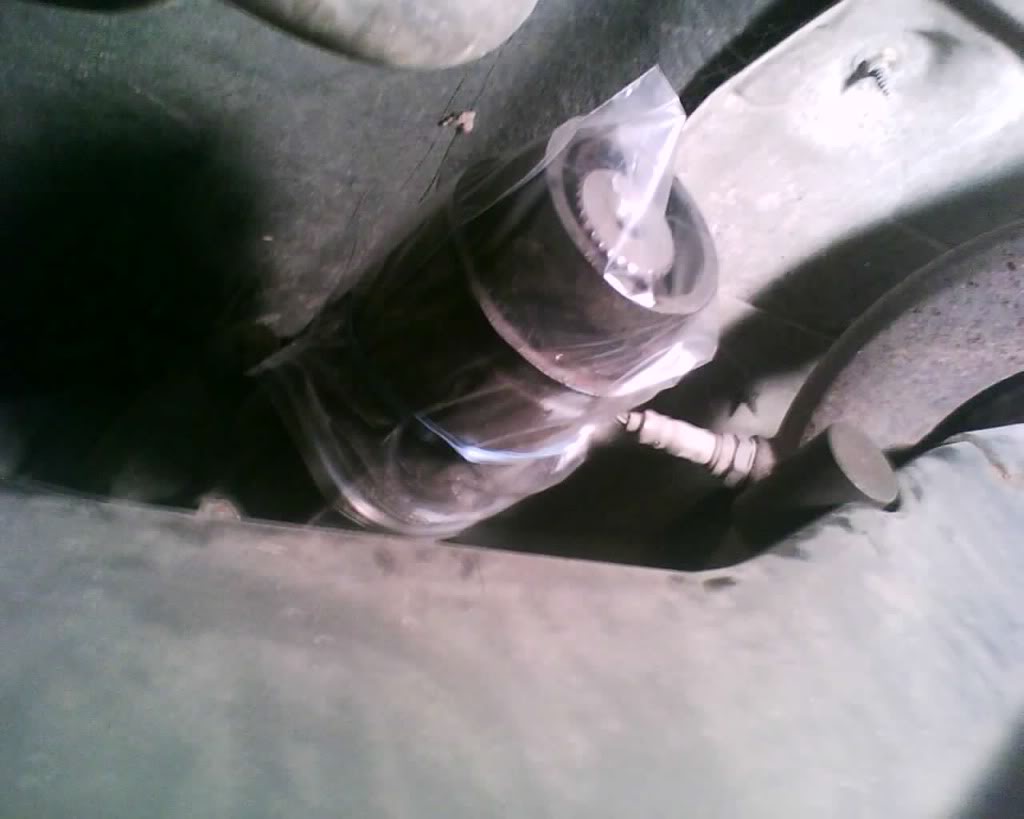
Take a plastic bag and put it on the opining at the tranny and secure with a rubber band this keeps fluid from leaking out and debris getting in. I also put one over the drive shaft end as well to keep clean.
pic
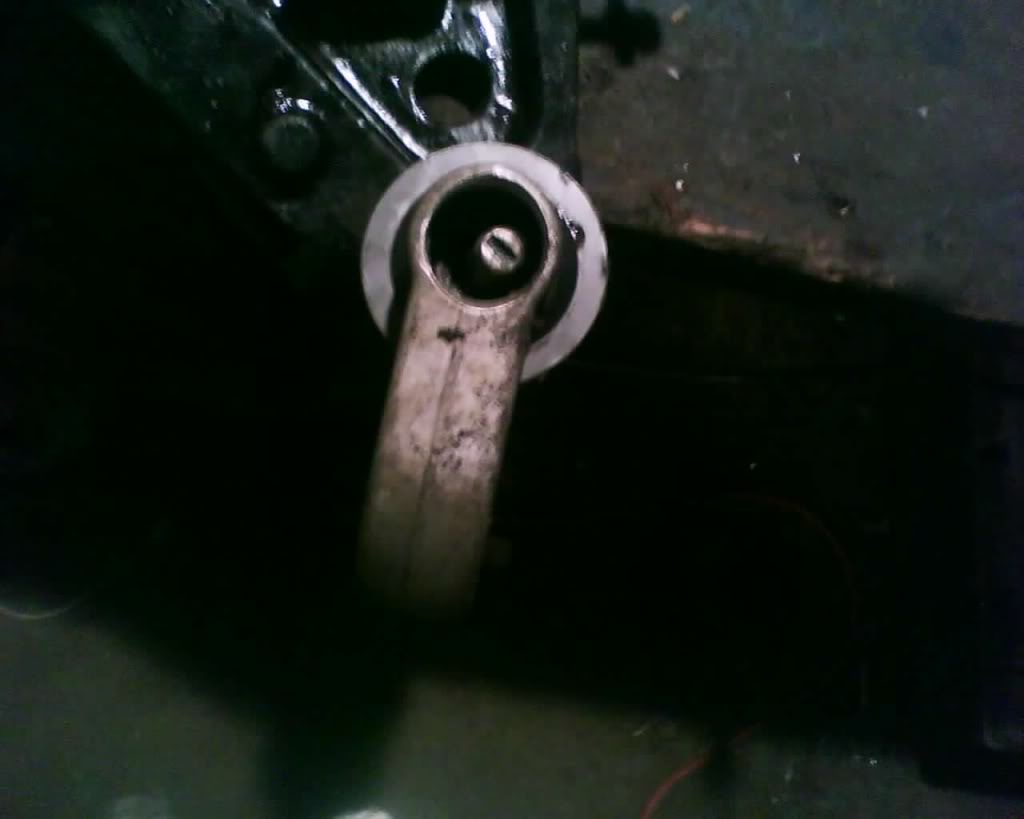
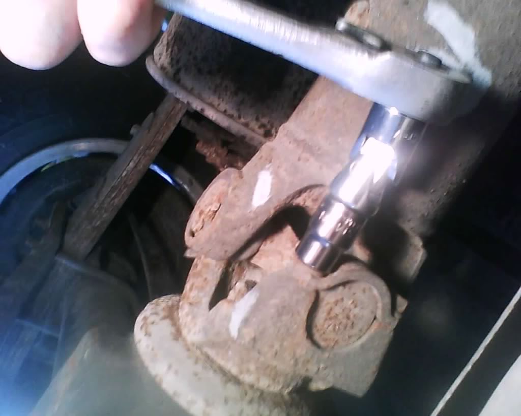
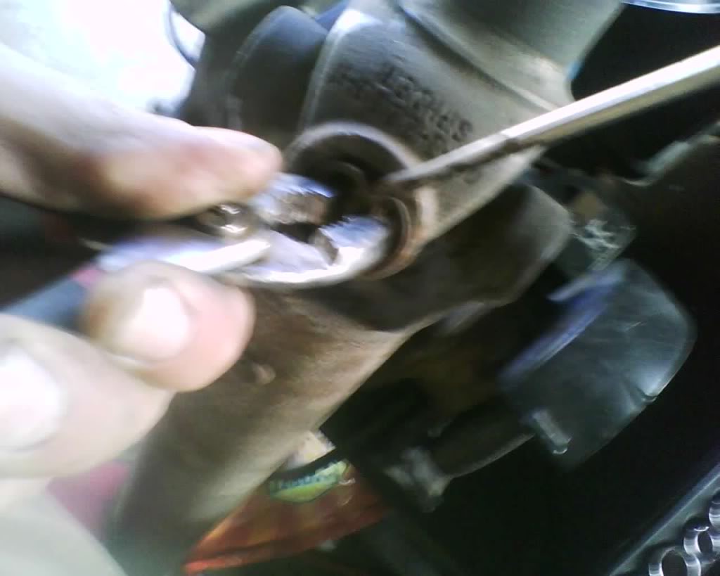
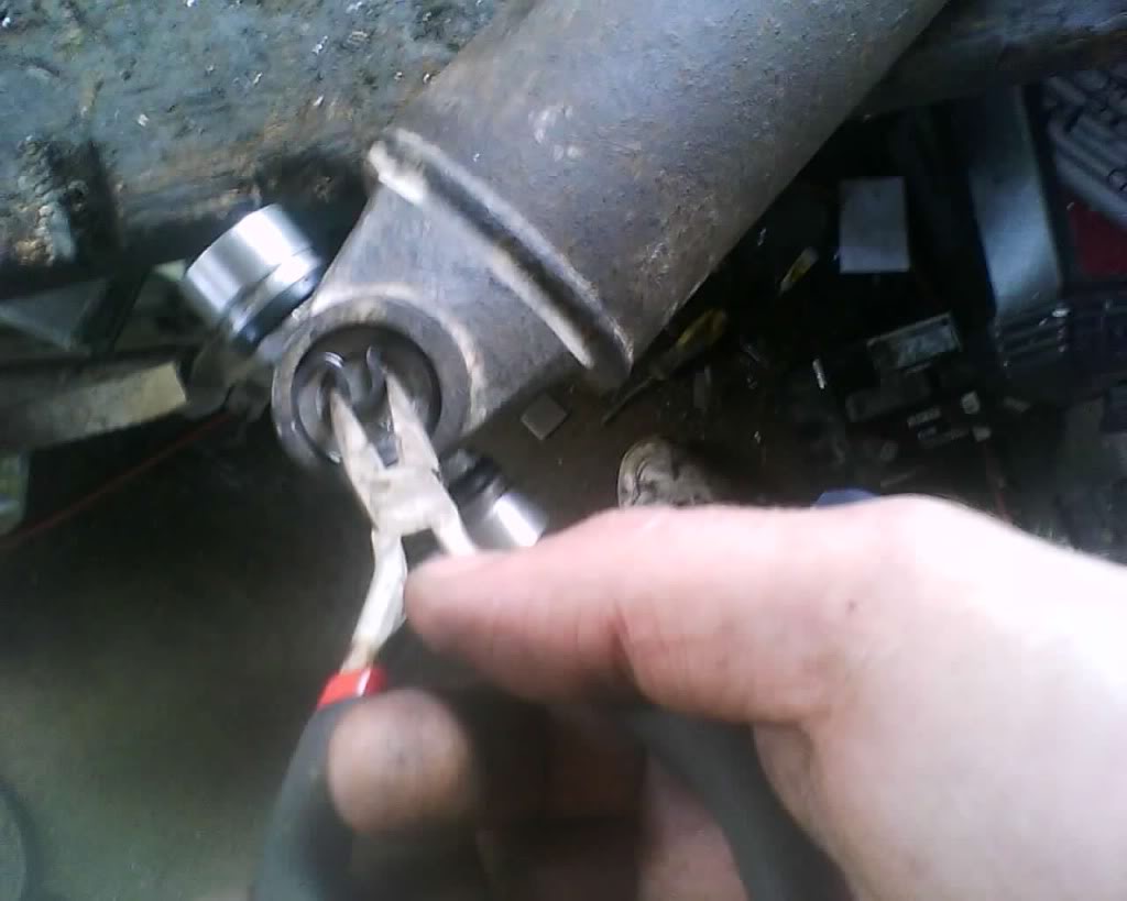
Next remove the retaining snap ring, as i said this is where putting PB blaster on a few days before helps brake the rust away and makes them come out much easier.
pic
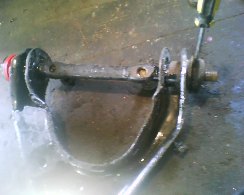
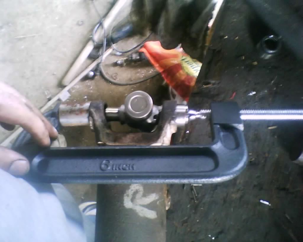
Now set it up like so, having a larger diameter socket on the bottom and a smaller diameter one on top, smack it with a hammer pushing the cap down into the socket. Do not miss and hit the drive shaft and damage it. my pic is not really level but u want to make this level as possible..
pic
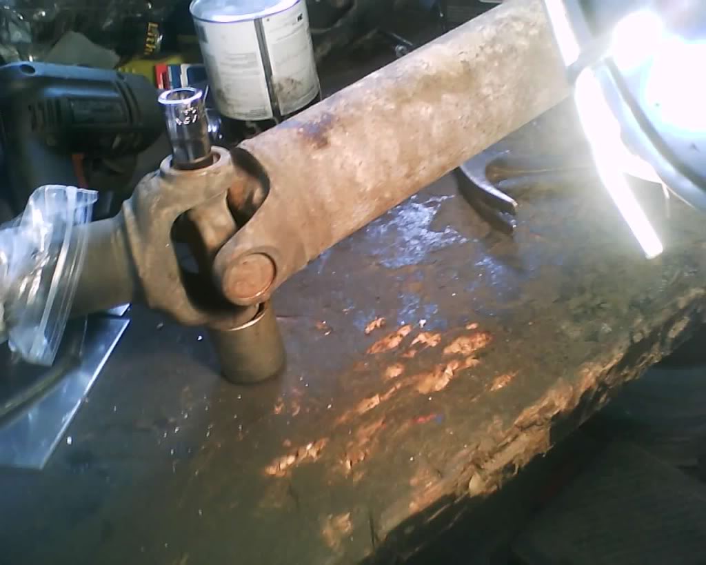
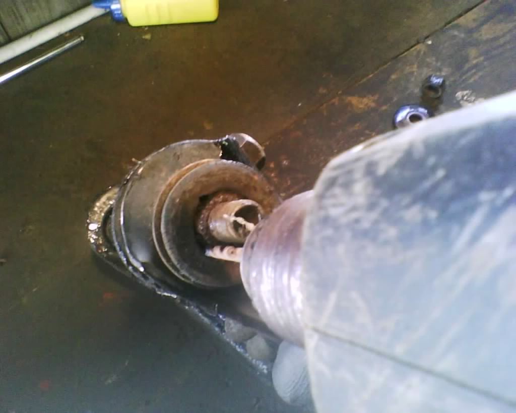
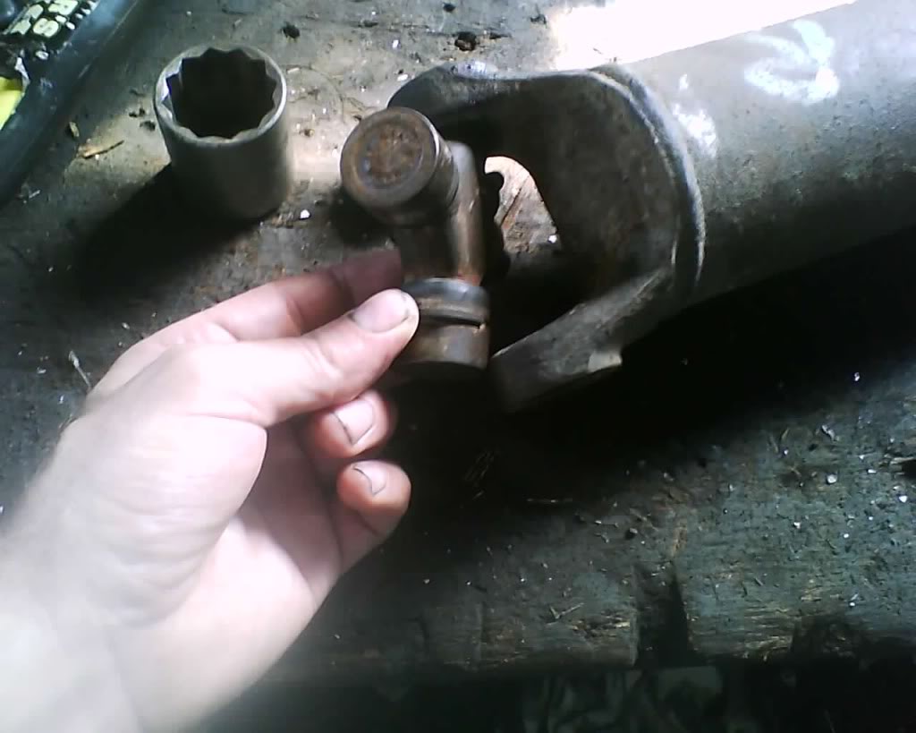
Now grab the end and pull it the rest of the way out.
pic
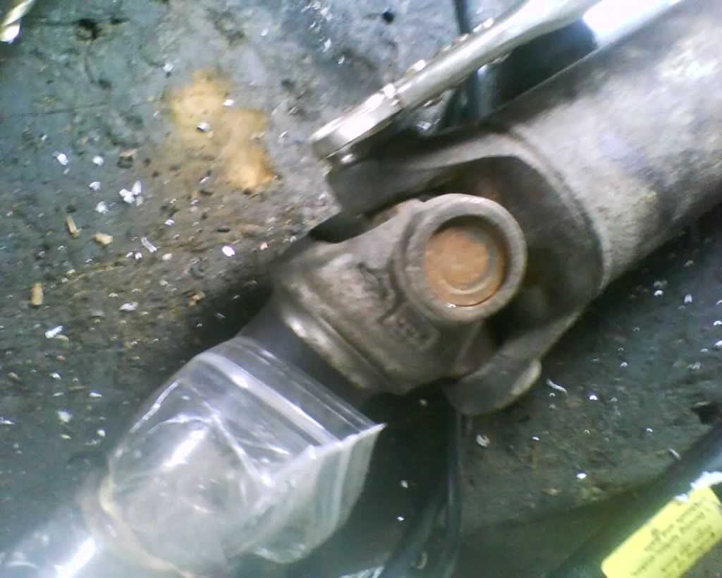
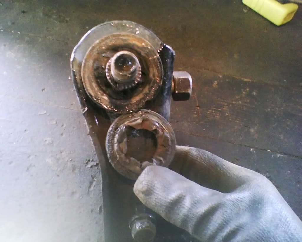
Now this part can kinda be a pain but u do not want to damage it when trying to get it out.
pic
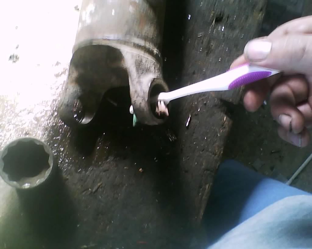
next you will want to clean it really well.. Check for burrs, clean the rust where the snap ring will go and also look for any cracks inside.
pic
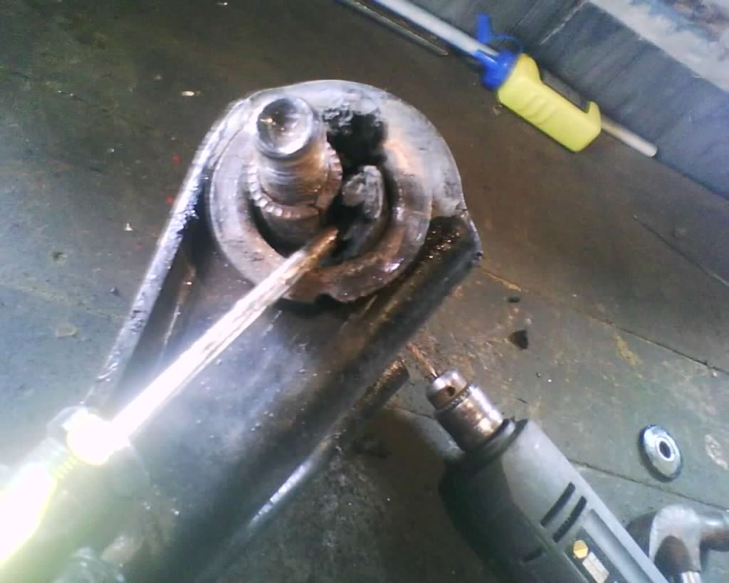
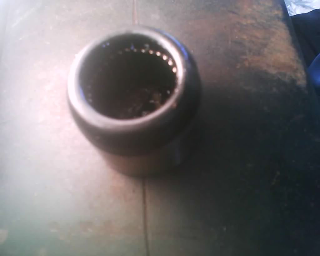
Before I go on with the install lets take a look at this pic, this is one of the end caps and if you look inside really close you will see a bunch of metal rod all the way around the outer edge, these are called needle bearings. Now nothing is really holding these there but grease. during this install i had to take a nail 3 times and move one of those back into place because it had fallen to the bottom. You must make sure u keep these in place or ur ujoint will not last very long, or may get it in just to have to take it back out because will not be able to get the snap ring to go all the way in.
pic
Now on this particular shaft at the yoke u can not just take one cap of and put it in, u have to take both off and press one in at a time from the outside, the front of the drive shaft i only had to take one cap off and press it from the outside while the other stayed on and was pushed threw from the inside. Dunno if this part is true or not but i always have been told this, in order to get the maximum strength out of the u-joint you need to set it in there like so, lets say u are looking at it from the tranny and the axle is turning right, u want the grease zerk setting to the right like so.. I hope this part makes sense to people lol
pic
now onto the install, push the first side in (i should note on the rear of this drive shaft one end cap is larger diameter then the other, the smaller diameter is the one you want to press in and the larger one is the one you strap back on to the differential)
pic
push the other side in
pic
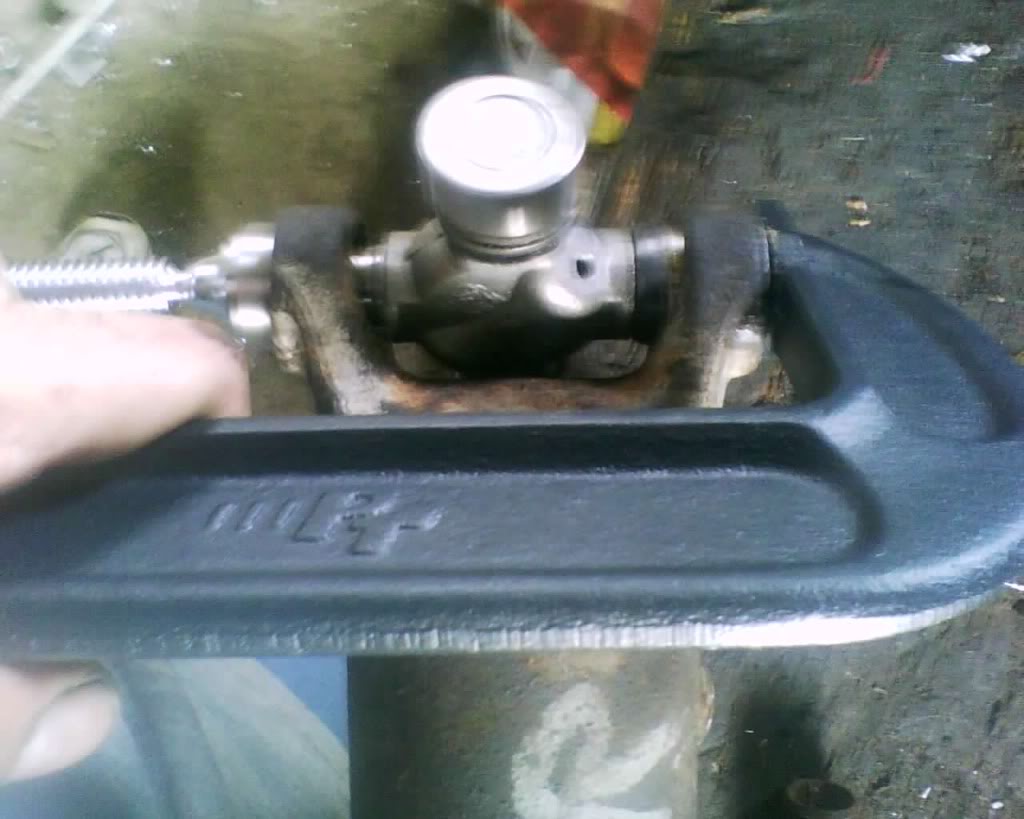
make sure u get it past the caps below the snap ring lip. and then install the snap rings
pic
Now i am going to tell ya right away that a china made C clamp is not going to work for this job, unless its a big one like a ball joint press.. You will want to have a nice American made C clamp for this job.
Install the drive shaft as u took it out by aligning up the marks, torque to spec and put grease in threw the zerts.
Your done...
The following guide is MY way in doing this and is done at at YOUR own risk. I am not responsible if you have something go wrong. This information should be used along with a service manual and always stay within your skill level, don't go tearing down the transmission if your only experience is changing the brakes another words. Start off slow and gain skills and knowledge to expand you abilities
I am going to list parts here
Precision U-Joints
458 Rear drive shaft this is the one that goes to the rear differential
354 Rear drive shaft this is the one that goes to the front of the rear drive shaft
380 Front drive shaft (4WD) this is the one that goes to the transfer case
369 Front drive shaft (4wd) this is the one that goes to the front differential
above is for 4wd not positive if those top two will work for a 2wd so you will want to check on that.
Tools
3/8 socket or wrench
Hammer
Quality C clamp
screw driver (standard)
pliers
needle nose pliers (don't have to but makes it nice to put snap ring back in)
Two sockets (dunno size but i used a 1 1/2 and the other i dunno to hit with a hammer to push the cap out)
Start by marking both ends so you can put the driveshaft in the same way you took it out. This is very important because if you do not then you may get a vibration and ruin ur new joints.
pic
and
pic
(i put the R and the F on thee to just show you, u do not need to do that unless you want to)
Next remove the rear u bolts/straps on the rear
pic
pry on the rear just a little be very careful here not to damage anything... don't let it slam to the ground, once lose from the rear simply pull that shaft from the transmission strait out
pic
Take a plastic bag and put it on the opining at the tranny and secure with a rubber band this keeps fluid from leaking out and debris getting in. I also put one over the drive shaft end as well to keep clean.
pic
Next remove the retaining snap ring, as i said this is where putting PB blaster on a few days before helps brake the rust away and makes them come out much easier.
pic
Now set it up like so, having a larger diameter socket on the bottom and a smaller diameter one on top, smack it with a hammer pushing the cap down into the socket. Do not miss and hit the drive shaft and damage it. my pic is not really level but u want to make this level as possible..
pic
Now grab the end and pull it the rest of the way out.
pic
Now this part can kinda be a pain but u do not want to damage it when trying to get it out.
pic
next you will want to clean it really well.. Check for burrs, clean the rust where the snap ring will go and also look for any cracks inside.
pic
Before I go on with the install lets take a look at this pic, this is one of the end caps and if you look inside really close you will see a bunch of metal rod all the way around the outer edge, these are called needle bearings. Now nothing is really holding these there but grease. during this install i had to take a nail 3 times and move one of those back into place because it had fallen to the bottom. You must make sure u keep these in place or ur ujoint will not last very long, or may get it in just to have to take it back out because will not be able to get the snap ring to go all the way in.
pic
Now on this particular shaft at the yoke u can not just take one cap of and put it in, u have to take both off and press one in at a time from the outside, the front of the drive shaft i only had to take one cap off and press it from the outside while the other stayed on and was pushed threw from the inside. Dunno if this part is true or not but i always have been told this, in order to get the maximum strength out of the u-joint you need to set it in there like so, lets say u are looking at it from the tranny and the axle is turning right, u want the grease zerk setting to the right like so.. I hope this part makes sense to people lol
pic
now onto the install, push the first side in (i should note on the rear of this drive shaft one end cap is larger diameter then the other, the smaller diameter is the one you want to press in and the larger one is the one you strap back on to the differential)
pic
push the other side in
pic
make sure u get it past the caps below the snap ring lip. and then install the snap rings
pic
Now i am going to tell ya right away that a china made C clamp is not going to work for this job, unless its a big one like a ball joint press.. You will want to have a nice American made C clamp for this job.
Install the drive shaft as u took it out by aligning up the marks, torque to spec and put grease in threw the zerts.
Your done...
Last edited by schusterjo; 09-17-2009 at 11:14 PM.
#40
09-06-2009, 08:17 PM
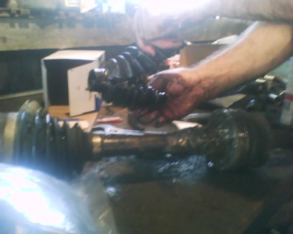
CV Boot replacement
I did not need to do everything they suggest doing in order to get the axle out, here is the proper way to remove the axle.
https://dodgeforum.com/forum/1383401-post2.html
and to remove the brake caliper and rotor refer to my brake thread here,
https://dodgeforum.com/forum/1793333-post31.html
Tie rod removal here, I do not suggest using a pickle fork if you plan on reusing the tie rod end, chances are high u will cut the boot on it and find yourself installing a new one on the tie rod end as well.
here is what the tool looks like that will remove tie rods without tearing the boot, you can rent at autozone/advance auto
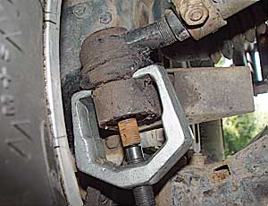
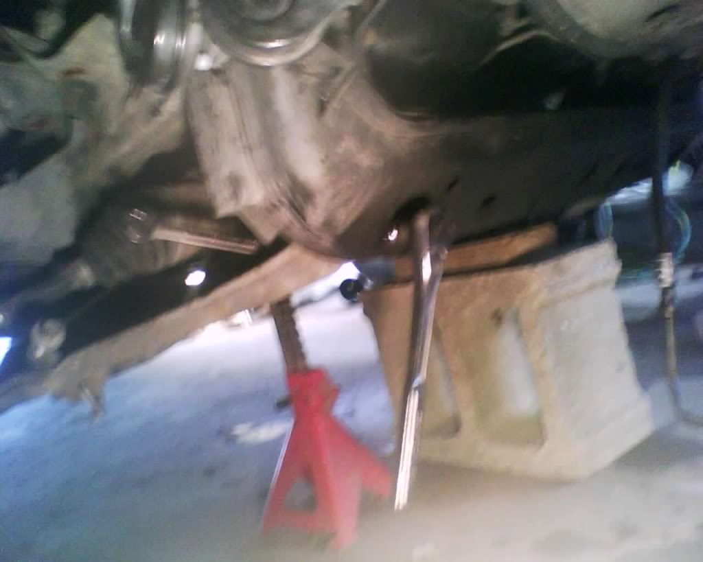
loosen the inner axle
pic
pull center cap remove cotter pin and cap the loosen outer axle bolt.
pic

pic

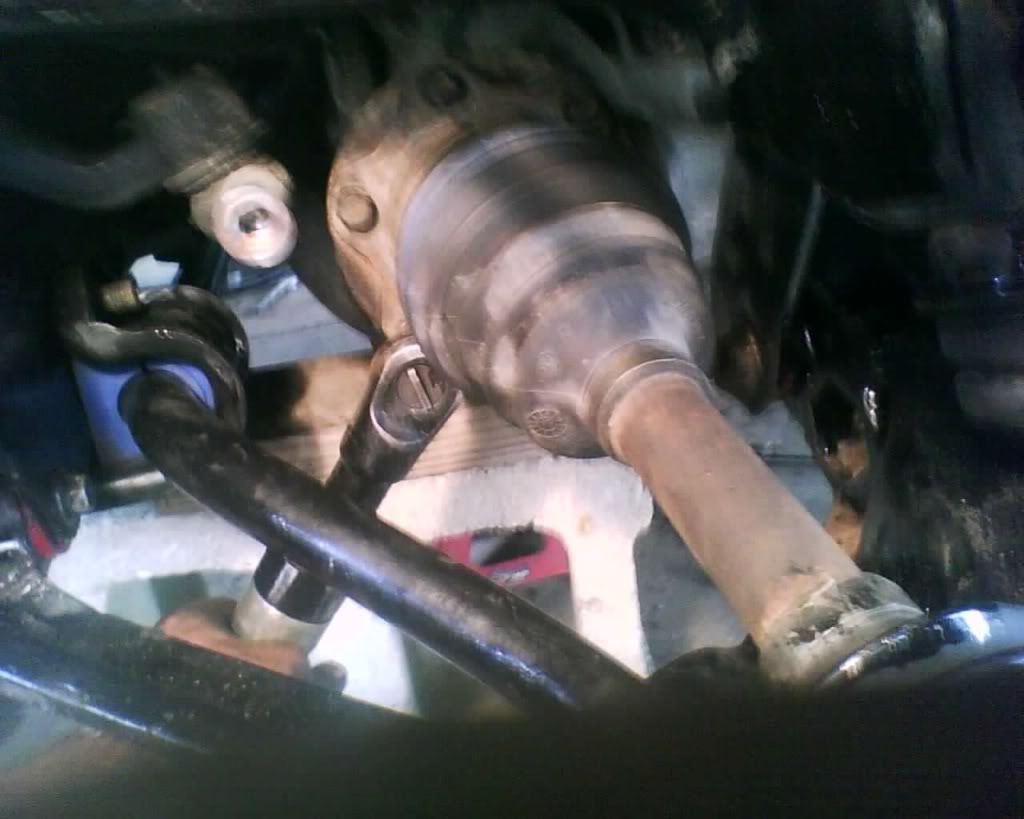
Loosen lug nuts and then jack up secure with jack stands, remove tire.
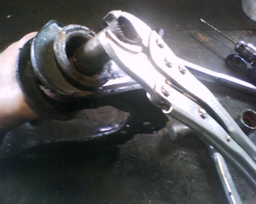
slide axle out, cut the outer ring and then cut the boot.
pic
pull it off
pic
pic
loosen the snap wring, first pic is hard to see it 2nd u can ... just loosen it an pull then it will come apart
pic
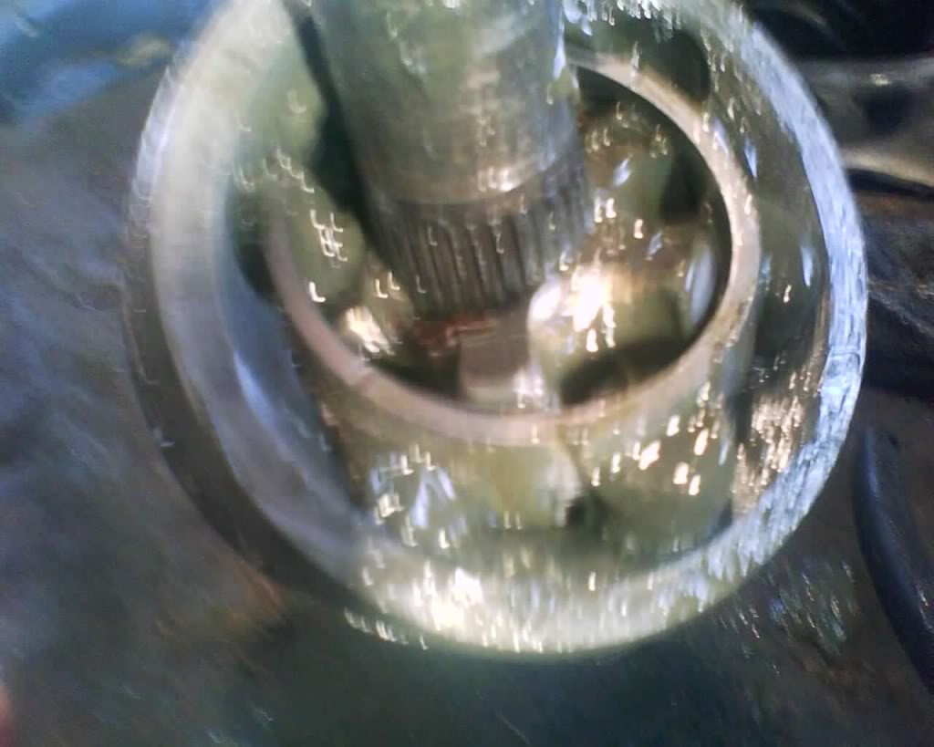
pic
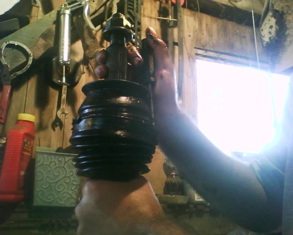
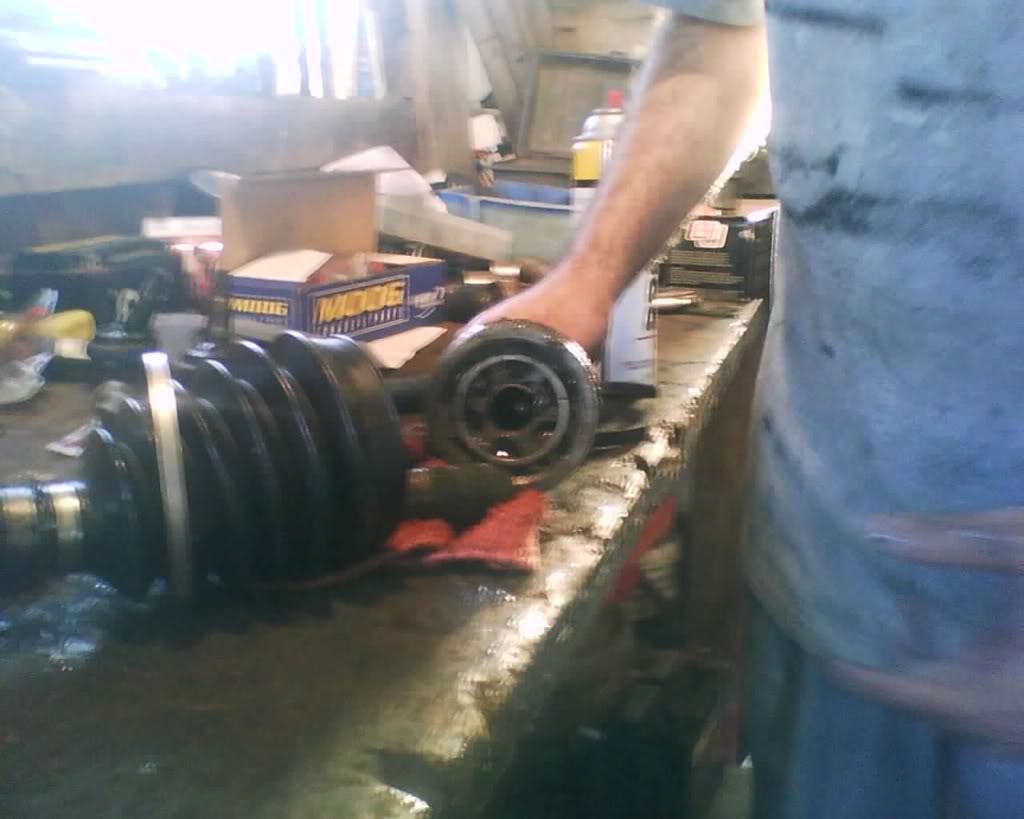
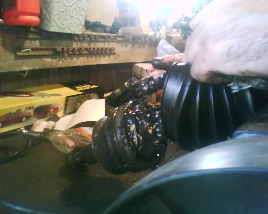
slide new boot on axle
pic
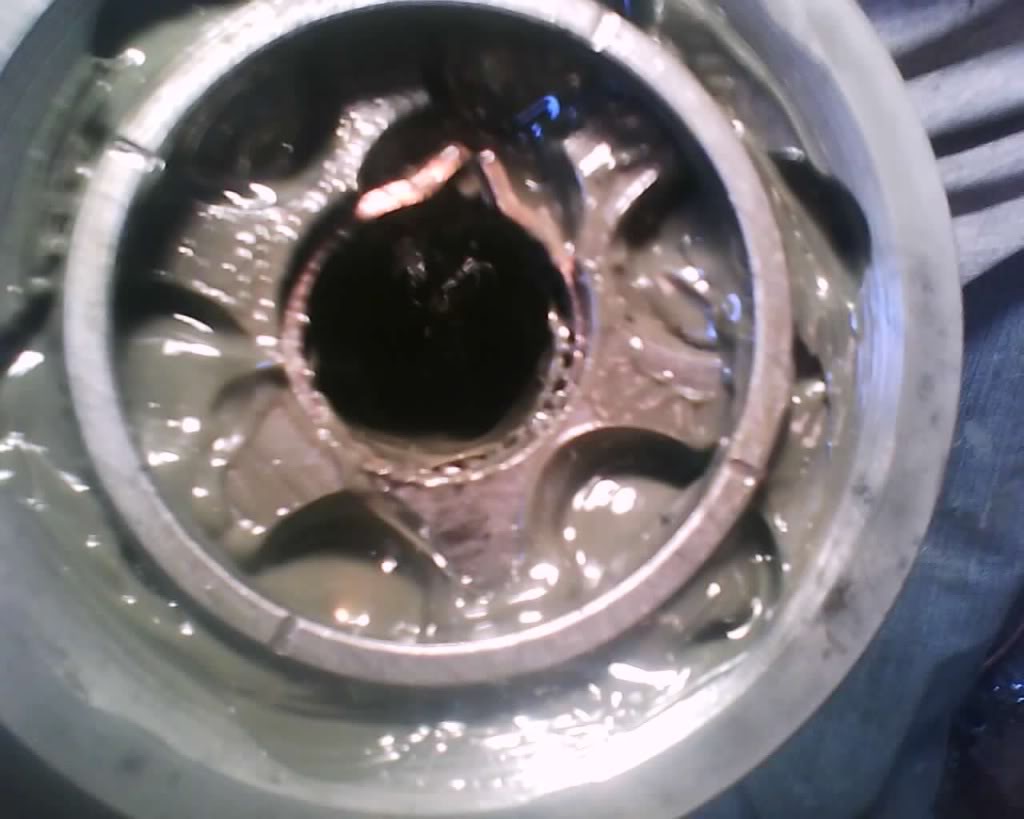
pack bearing wit h grease
pic
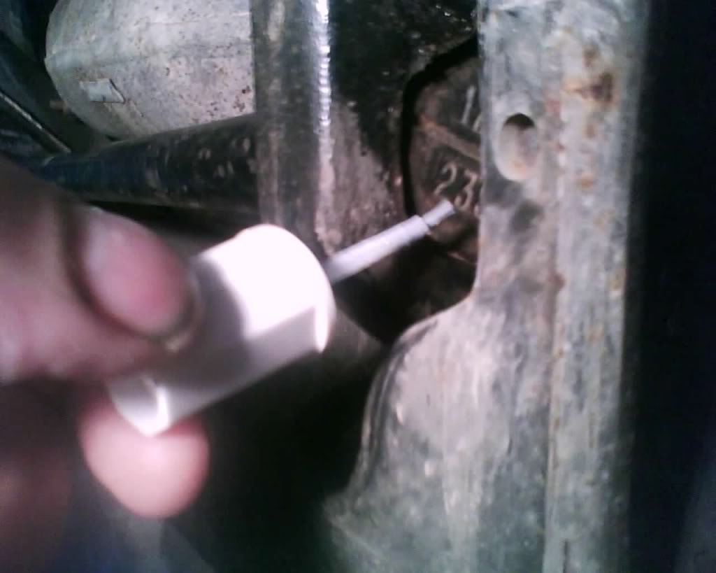
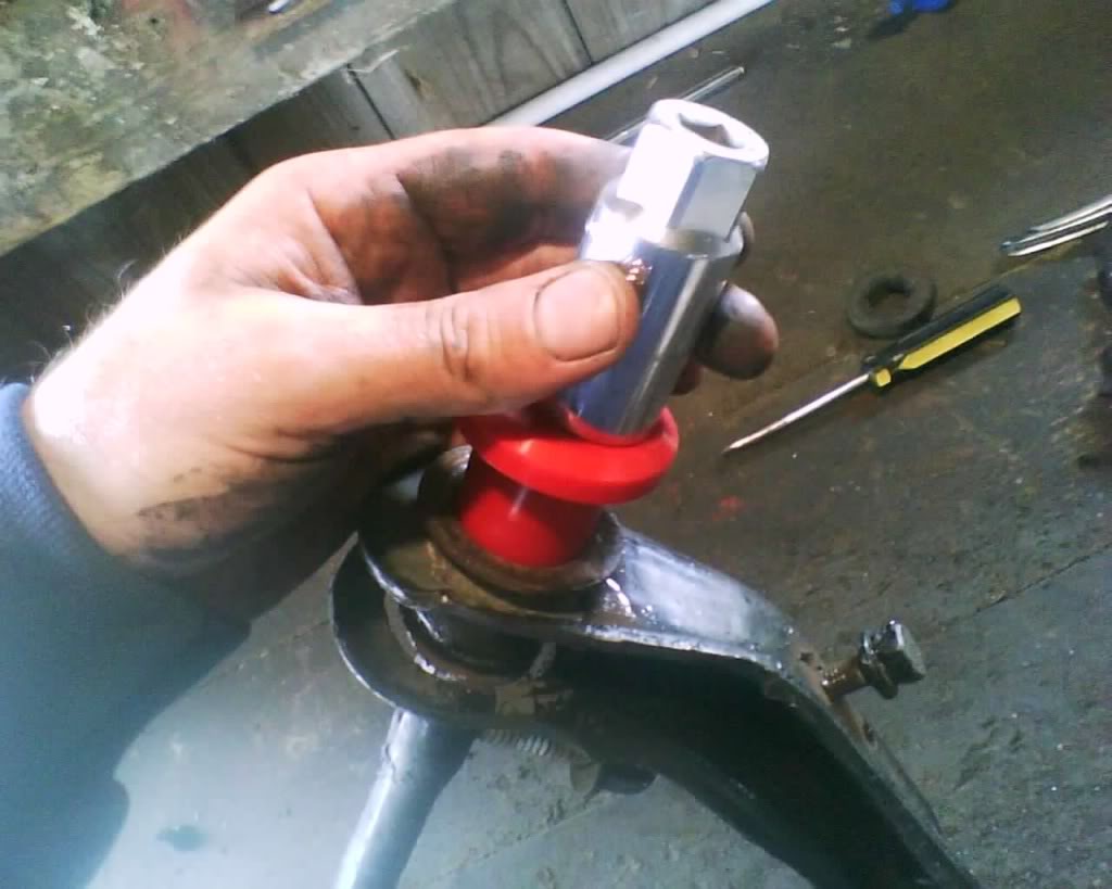
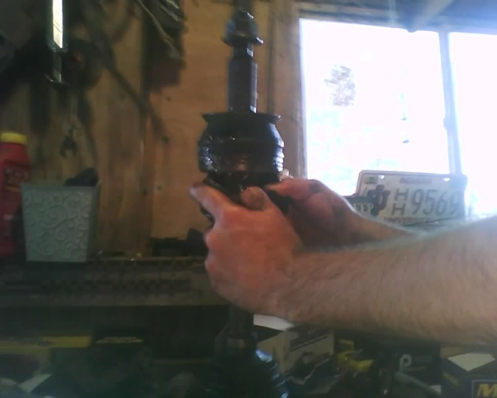
slide it on and then use a cv boot ring tool ($8) to tighten both rings, you will need to burp these before you tighten the rings. take a screw driver and open the larger end up and squeeze a little to push some air out then pull screw driver out, then tighten cv boot retaining ring with tool.
pic
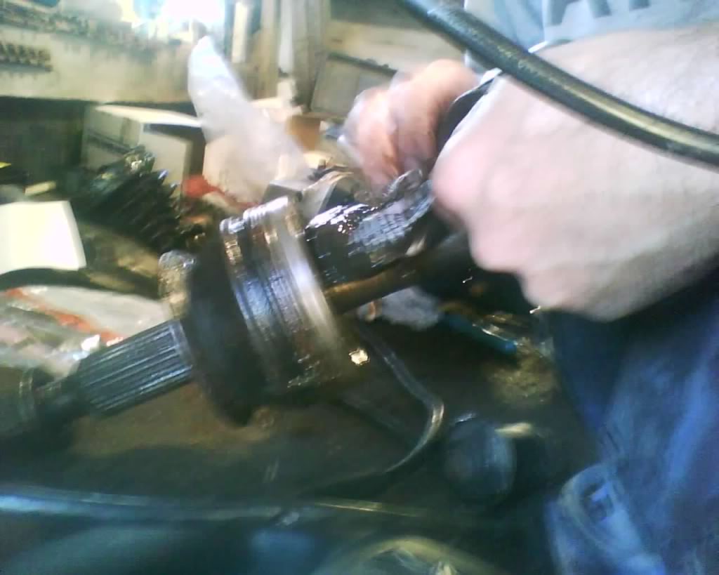
pic
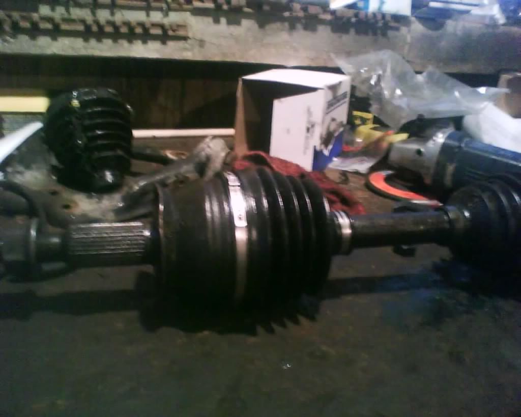
About $20 bucks for tool and cv boot and u saved $40-50
Reinstall.
The following guide is MY way in doing this and is done at at YOUR own risk. I am not responsible if you have something go wrong. This information should be used along with a service manual and always stay within your skill level, don't go tearing down the transmission if your only experience is changing the brakes another words. Start off slow and gain skills and knowledge to expand you abilities
https://dodgeforum.com/forum/1383401-post2.html
and to remove the brake caliper and rotor refer to my brake thread here,
https://dodgeforum.com/forum/1793333-post31.html
Tie rod removal here, I do not suggest using a pickle fork if you plan on reusing the tie rod end, chances are high u will cut the boot on it and find yourself installing a new one on the tie rod end as well.
here is what the tool looks like that will remove tie rods without tearing the boot, you can rent at autozone/advance auto
loosen the inner axle
pic
pull center cap remove cotter pin and cap the loosen outer axle bolt.
pic
pic
Loosen lug nuts and then jack up secure with jack stands, remove tire.
slide axle out, cut the outer ring and then cut the boot.
pic
pull it off
pic
pic
loosen the snap wring, first pic is hard to see it 2nd u can ... just loosen it an pull then it will come apart
pic
pic
slide new boot on axle
pic
pack bearing wit h grease
pic
slide it on and then use a cv boot ring tool ($8) to tighten both rings, you will need to burp these before you tighten the rings. take a screw driver and open the larger end up and squeeze a little to push some air out then pull screw driver out, then tighten cv boot retaining ring with tool.
pic
pic
About $20 bucks for tool and cv boot and u saved $40-50
Reinstall.
Last edited by schusterjo; 09-17-2009 at 11:25 PM.

