

Swapping Pull Knob for Turn Knob Headlamp Switch
#1
 05-28-2011, 08:17 PM

I'm trying to swap in a newer turn **** switch in place of my pull **** one. The pull **** was found only in '98, and '99+ had the turn know switch. I have both a 1998 and 2000 service manual with all the schematics and pin-outs, but I need a little help.
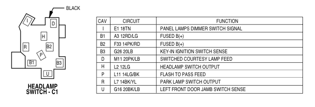
Here is the pin-out for 1998:
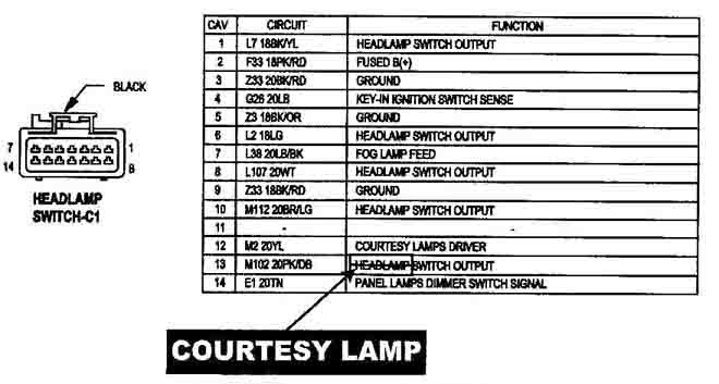
...and the pin-out for 2000:
The connections I have made are ('00 --> '98):
1 --> R
2 --> B1
3,5,9 --> Ground
4 --> B3
12 --> Separate connector (not shown)
13 --> D
14 --> I
One issue I can see is that the '98 switch has two fused circuits, B1 and B2, where as the '00 has just one fused circuit. B1 showed 12V coming through, but B2 did not. On the other hand, if I used the multimeter on B1 and placed the other terminal on B2, it showed 12V. (Does this mean that B2 is acting as ground?) Also using my multimeter, I found that when the headlights are turned on, H and B2 come in contact. This clearly shows that both B2 and B1 need to be used, because B1 provides power, and B2 must be some kind of signal for the headlights.
With pin 2 being connected to B1, pins 1 and 8 showed 12V, but 6 and 10 did not. If either pins 1 or 8 was connected to H, the headlights would come on, but in both the parking light and headlight positions. I assume that would be right, but for the parking lamps only. Not a single combination I did made the headlights only work when placed in the headlight position: they always came on even in parking lamp mode only.
I can get you any kind of schematics you need, I just want this to work.
Here is the pin-out for 1998:
...and the pin-out for 2000:
The connections I have made are ('00 --> '98):
1 --> R
2 --> B1
3,5,9 --> Ground
4 --> B3
12 --> Separate connector (not shown)
13 --> D
14 --> I
One issue I can see is that the '98 switch has two fused circuits, B1 and B2, where as the '00 has just one fused circuit. B1 showed 12V coming through, but B2 did not. On the other hand, if I used the multimeter on B1 and placed the other terminal on B2, it showed 12V. (Does this mean that B2 is acting as ground?) Also using my multimeter, I found that when the headlights are turned on, H and B2 come in contact. This clearly shows that both B2 and B1 need to be used, because B1 provides power, and B2 must be some kind of signal for the headlights.
With pin 2 being connected to B1, pins 1 and 8 showed 12V, but 6 and 10 did not. If either pins 1 or 8 was connected to H, the headlights would come on, but in both the parking light and headlight positions. I assume that would be right, but for the parking lamps only. Not a single combination I did made the headlights only work when placed in the headlight position: they always came on even in parking lamp mode only.
I can get you any kind of schematics you need, I just want this to work.
Last edited by devinpitcher; 05-29-2011 at 06:53 AM.
#2
05-30-2011, 10:37 AM
Ok, found some more information on the CTM and Hadlamps in the '98 Service Manual:
So by connecting the H or R pins to ground, that activates the lights?
The headlamp switch is located in the instrument panel, outboard of the steering column. It closes a path to ground for the Central Timer Module (CTM) when the park or head lamps are on and the driver door ajar switch is closed (driver door is open). The headlamp switch opens the ground path when the headlamp switch is turned off. The ground path is also opened when the driver door ajar switch is open (driver door is closed).
The headlamp switch cannot be repaired and, if faulty or damaged, it must be replaced. Refer to Headlamp Switch in the Removal and Installation section of Group 8E - Instrument Panel Systems for the service procedures.
The headlamp switch cannot be repaired and, if faulty or damaged, it must be replaced. Refer to Headlamp Switch in the Removal and Installation section of Group 8E - Instrument Panel Systems for the service procedures.
The headlamp (or security) relay is a International Standards Organization (ISO) micro-relay. The termi- nal designations and functions are the same as a con- ventional ISO relay. However, the micro-relay terminal orientation (or footprint) is different, cur- rent capacity is lower, and the relay case dimensions are smaller than those of the conventional ISO relay.
The headlamp relay is a electromechanical device that switches battery current to the headlamps when the high-line Central Timer Module (CTM) grounds the relay coil. See Headlamp Relay in the Diagnosis and Testing section of this group for more information.
The headlamp relay is a electromechanical device that switches battery current to the headlamps when the high-line Central Timer Module (CTM) grounds the relay coil. See Headlamp Relay in the Diagnosis and Testing section of this group for more information.
Last edited by devinpitcher; 05-30-2011 at 10:41 AM.
#5
05-30-2011, 04:53 PM
#6
10-20-2012, 10:25 PM

Registered User
Thanks in advance.
#7
10-20-2012, 10:32 PM

Trending Topics
#9
10-21-2012, 09:46 AM
Record Breaker