
My Official Solid Axle Swap Thread (The Project Writeup)
#1
 03-14-2010, 03:49 PM

Since the other thread was getting long and crowded, I decided to start a new one for the swap itself. I'm going to start by asking everybody to refrain from posting in this thread to keep it uncluttered. Please post any questions or comments in the other one...
https://dodgeforum.com/forum/1st-gen...ap-thread.html
__________________________________________________
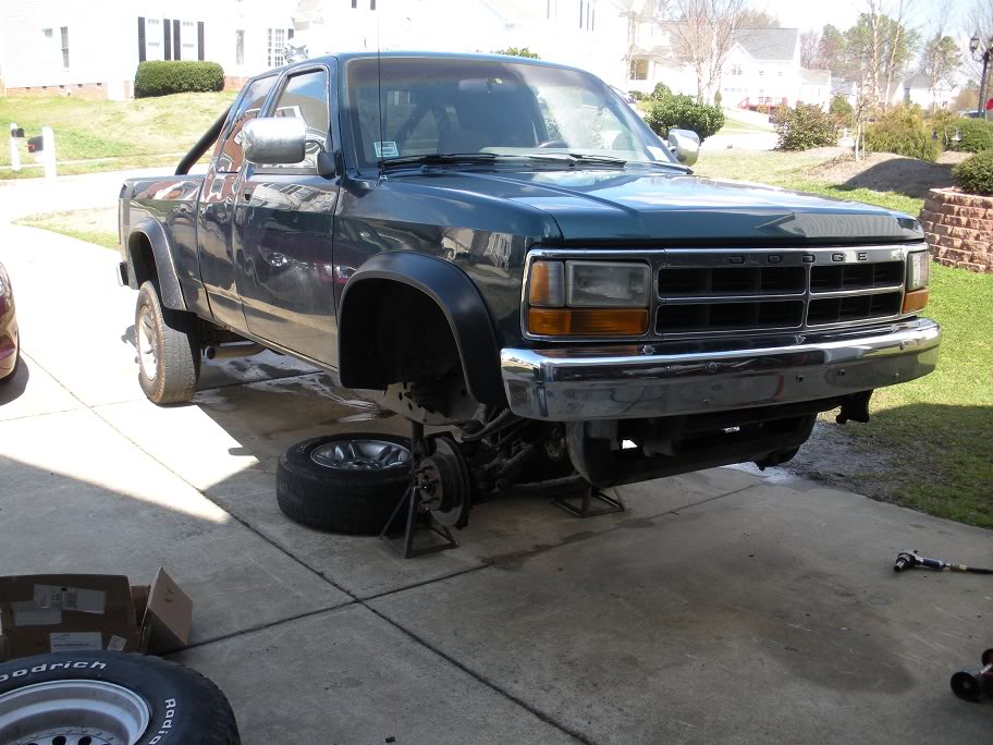
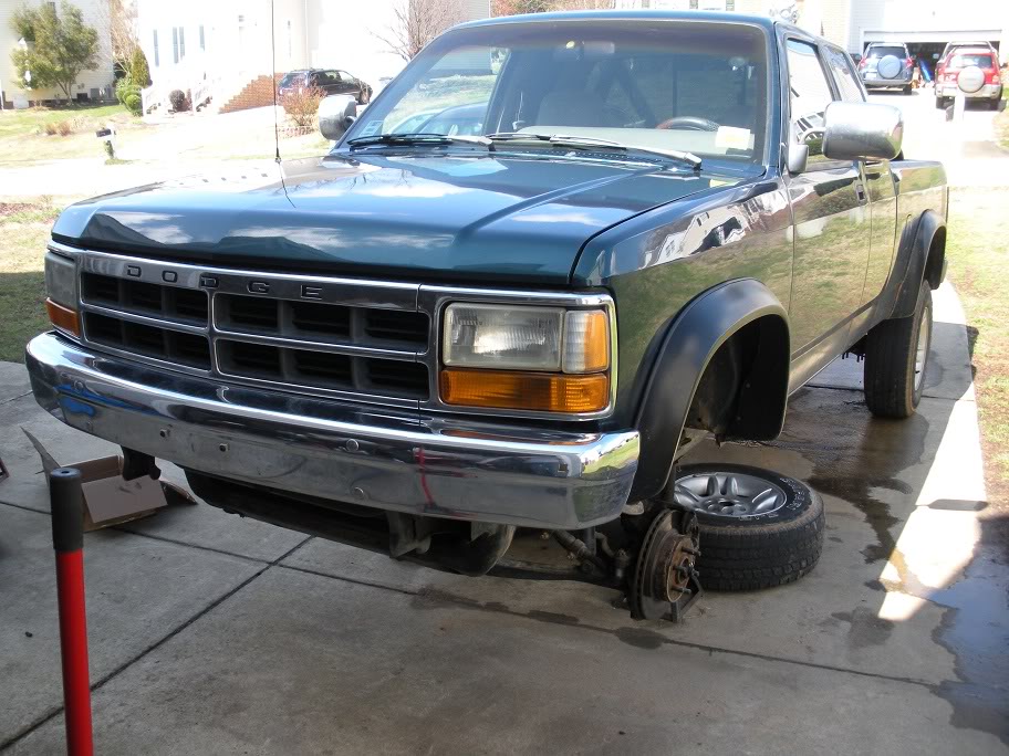
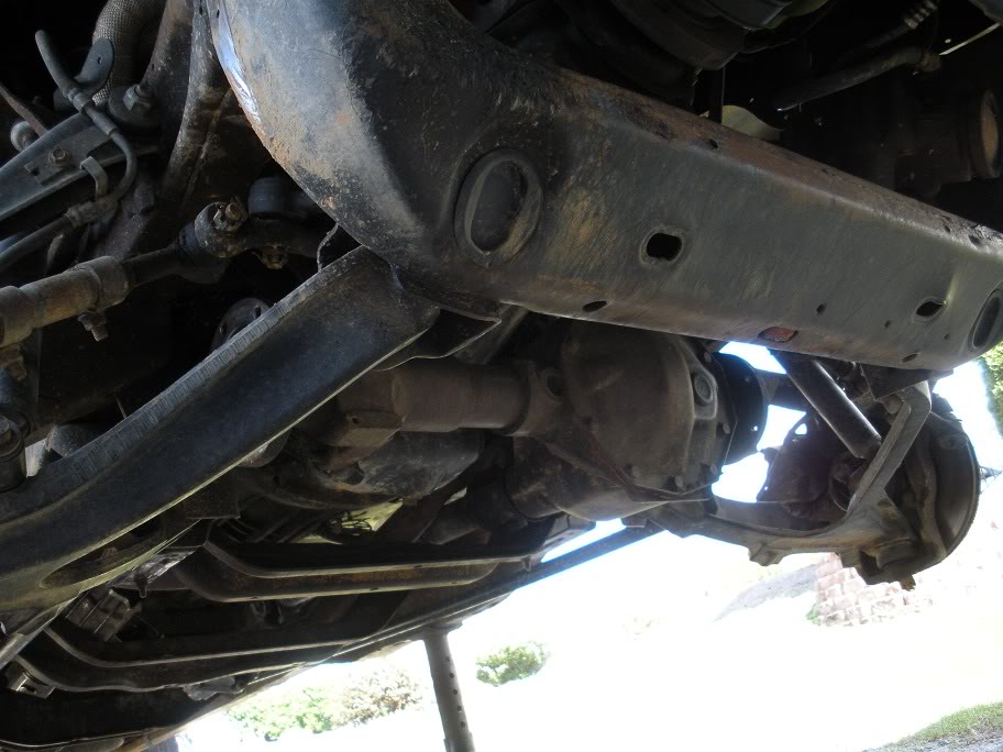
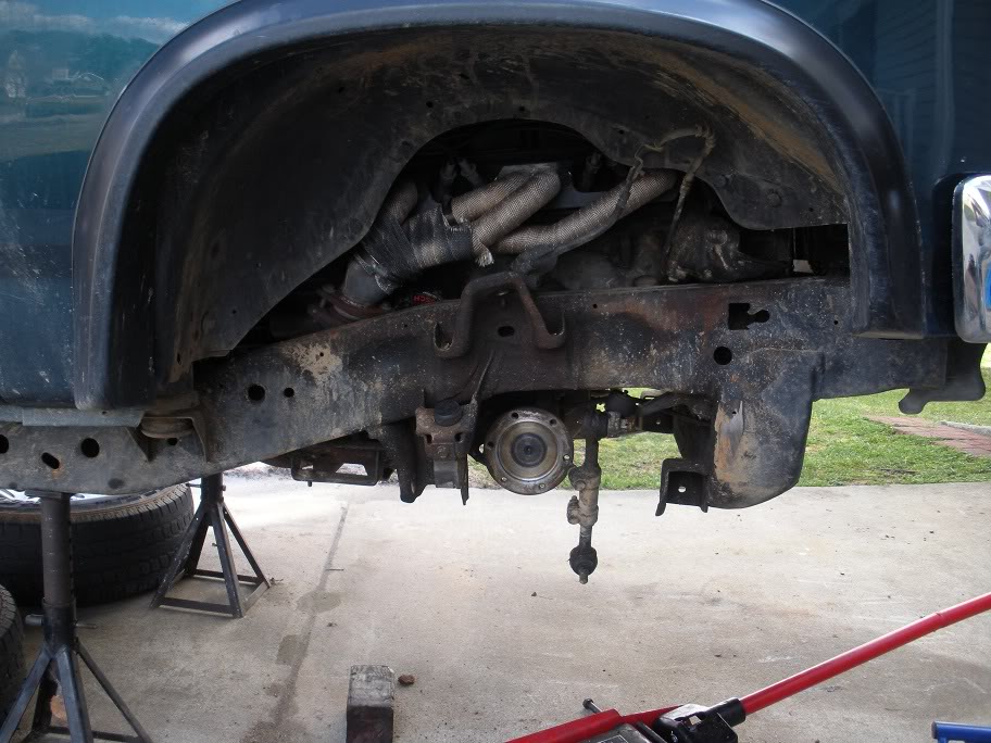
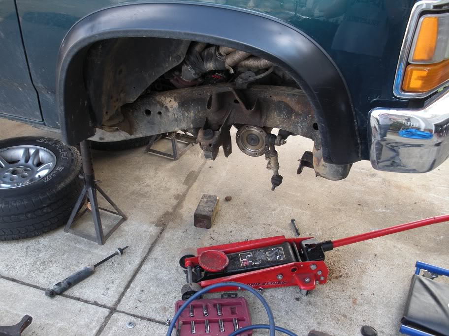
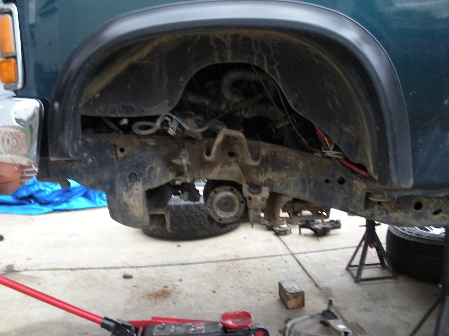
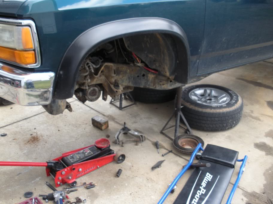
So to start, I am doing a solid axle wwap on my '95 Dakota 4x4. I'll be using a 1979 Ford F250 Heavy Duty, High Pinion Dana 44 front axle and a mid 70's (actual year unknown) Chevy 14 Bolt Full Floating rear axle. Both axles have a 4.1 gear ratio and 8x6.5 lug pattern. I'm going to build a custom 3 link suspension with coil springs for the front and I'll sticking with leaf springs in the rear but I'll be doing a shackle flip with longer shackles and custom hangers.
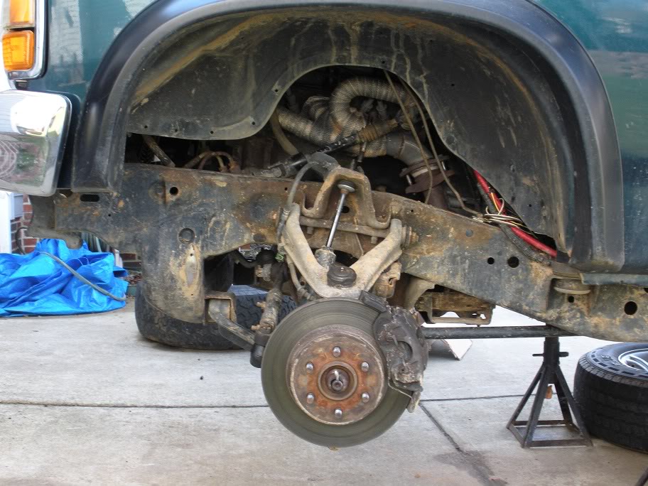
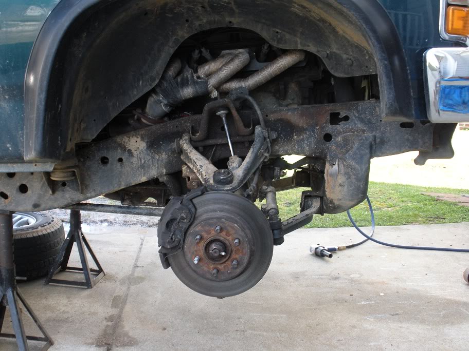
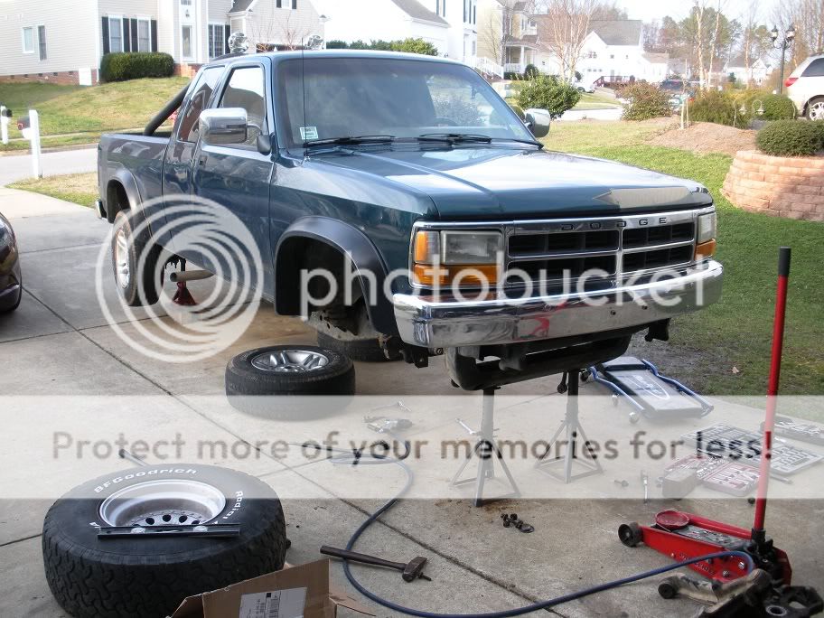
Of course, starting this swap requires removing all of the factory independent front suspension from the truck. I'm not going into any detail on how to do this, because if you can't figure it out, this is not a swap you need to take on. But here are some pictures of the teardown...
https://dodgeforum.com/forum/1st-gen...ap-thread.html
__________________________________________________
So to start, I am doing a solid axle wwap on my '95 Dakota 4x4. I'll be using a 1979 Ford F250 Heavy Duty, High Pinion Dana 44 front axle and a mid 70's (actual year unknown) Chevy 14 Bolt Full Floating rear axle. Both axles have a 4.1 gear ratio and 8x6.5 lug pattern. I'm going to build a custom 3 link suspension with coil springs for the front and I'll sticking with leaf springs in the rear but I'll be doing a shackle flip with longer shackles and custom hangers.
Of course, starting this swap requires removing all of the factory independent front suspension from the truck. I'm not going into any detail on how to do this, because if you can't figure it out, this is not a swap you need to take on. But here are some pictures of the teardown...
Last edited by 95_318SLT; 05-11-2010 at 07:22 PM.
#2
03-14-2010, 03:56 PM
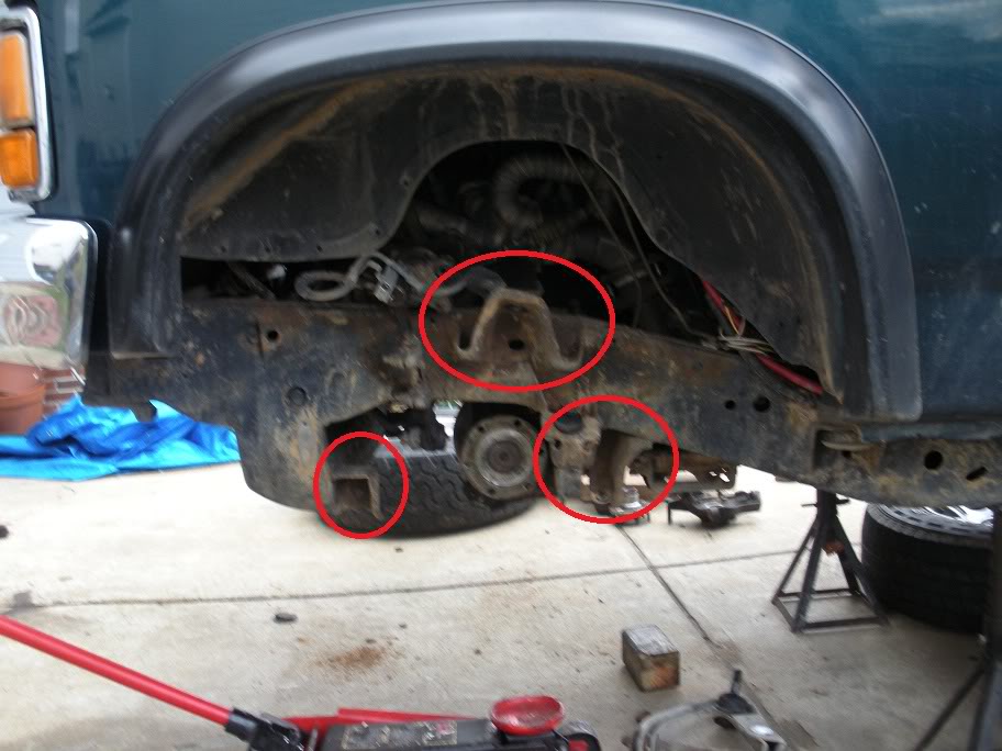
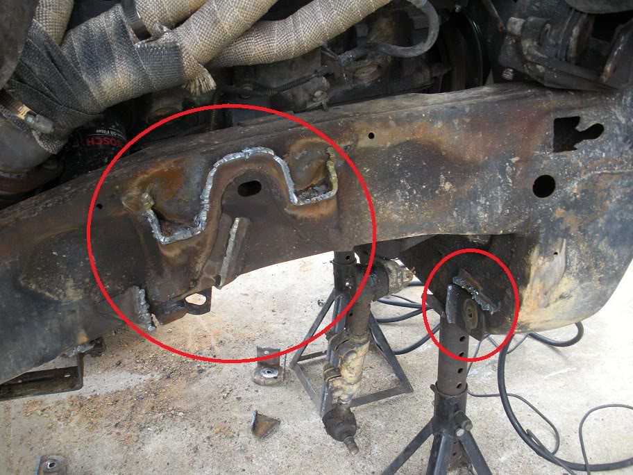
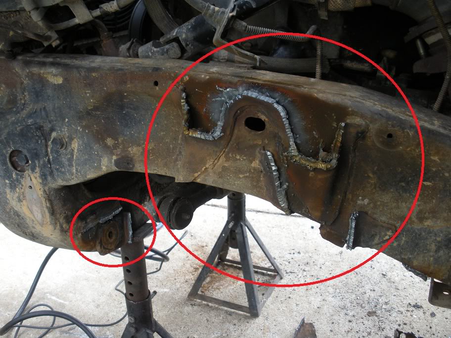
Of course that was all the easy part. Next comes the point of no return. Circled are the mounts that will have to be cut off the frame. There are many ways to do this... a cut off wheel, which would take forever, an oxy-acy torch, which would be very messy, so I decided to go with a plasma cutter to make it quick and easy. I rented the plasma cutter locally.
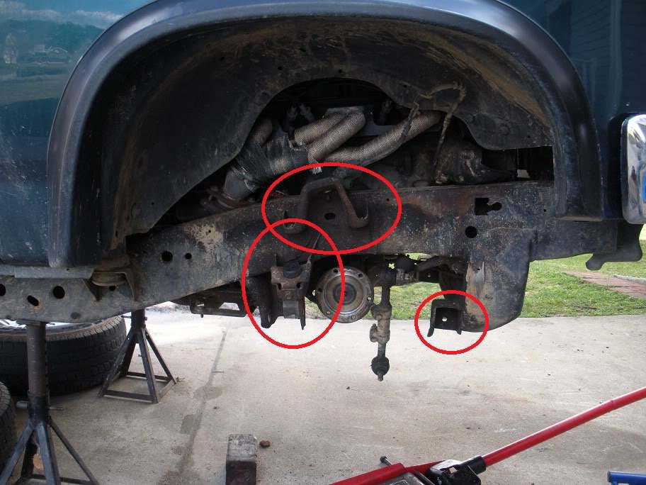
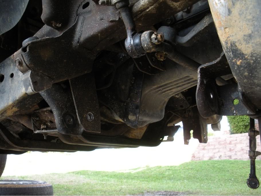
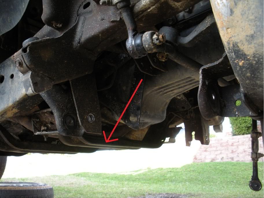
Also, this crossmemeber needs to come out while you are up there cutting stuff loose...
Also, this crossmemeber needs to come out while you are up there cutting stuff loose...
Last edited by 95_318SLT; 05-11-2010 at 07:22 PM.
#3
03-14-2010, 06:31 PM
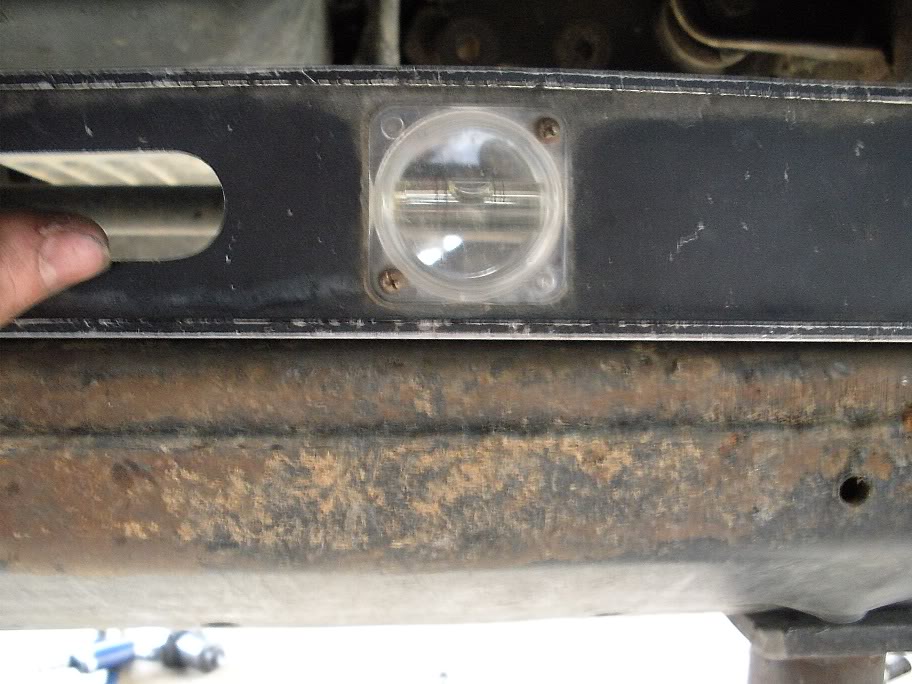
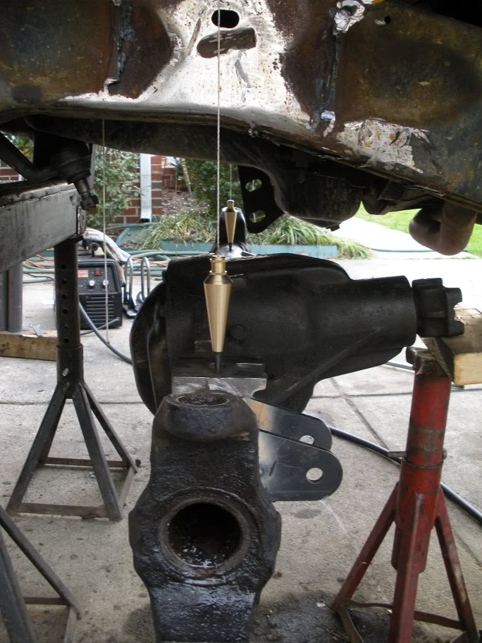
Now, before I got any further, I decided it would be a good idea to get the truck level, that way I can use a plumbers bob to locate the new axle later. It would have been a good idea to level the truck first, but I didn't think of it at the time.
On the frame rail, under where the bed and cab meet at the flattest spot of the frame...

Across the front crossmemeber...
On the frame rail, under where the bed and cab meet at the flattest spot of the frame...
Across the front crossmemeber...
Last edited by 95_318SLT; 05-11-2010 at 07:23 PM.
#4
03-15-2010, 04:59 PM
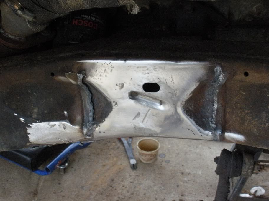
Today I made the rough cuts to remove the factory suspension mounts. Next I'll have to trim away the rest and grind off whatever the plasma cutter can't get to.
Last edited by 95_318SLT; 05-11-2010 at 07:24 PM.
#5
03-16-2010, 06:41 PM
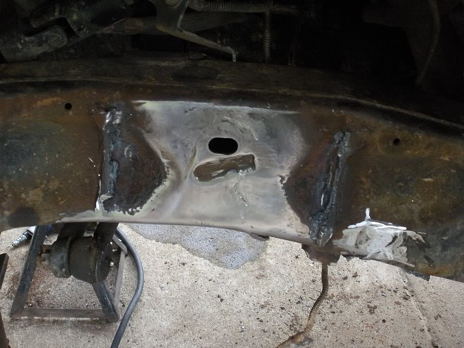
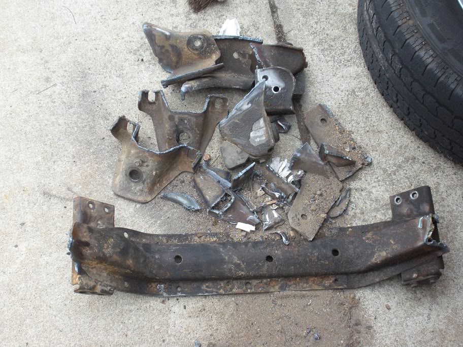
Got more of the remaining peices of the mounts cut off and smoothed out today. I ended using a grinder to thin out the welds and an air hammer to cut off the peices. I have a few more to knock off tomorrow morning and hopefully with any luck I'll start lining the axle up in the afternoon.
And I also did the rough cut on the crossmemeber today as well. Recall this is the crossmember that is directly under the y-pipe.
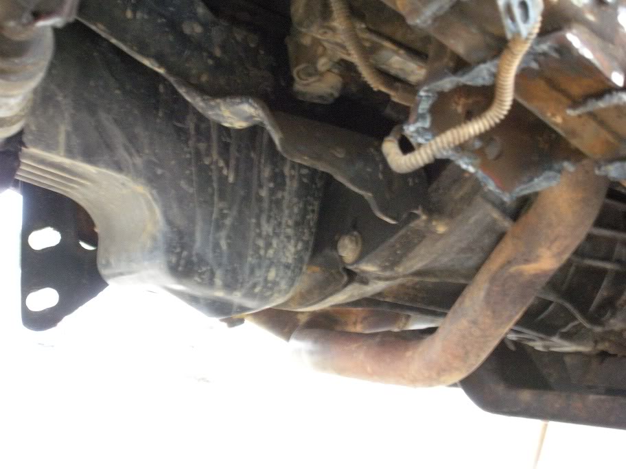
And just for kicks, here is the pile of metal I cut off the frame...
And I also did the rough cut on the crossmemeber today as well. Recall this is the crossmember that is directly under the y-pipe.
And just for kicks, here is the pile of metal I cut off the frame...
Last edited by 95_318SLT; 05-11-2010 at 07:25 PM.
#6
03-18-2010, 08:45 AM
So with the frame nearly stripped clean of the mounts and crossmember, it was time today to go ahead and start building the 3 link to place the axle! A big thanks goes out to Sheriff420 of the 2nd Gen Ram section for coming over and giving me a hand! (A good reason to see if DF has a local club section like the NC club!)
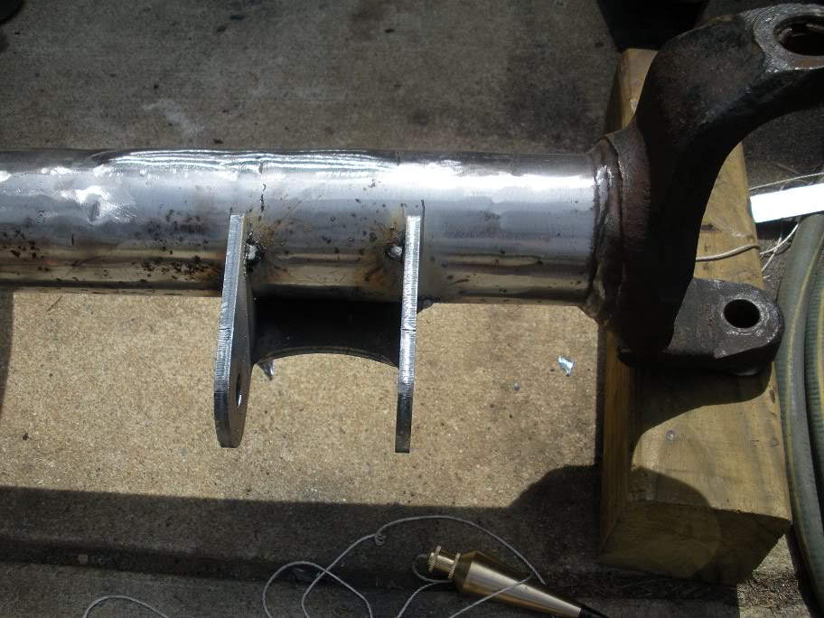
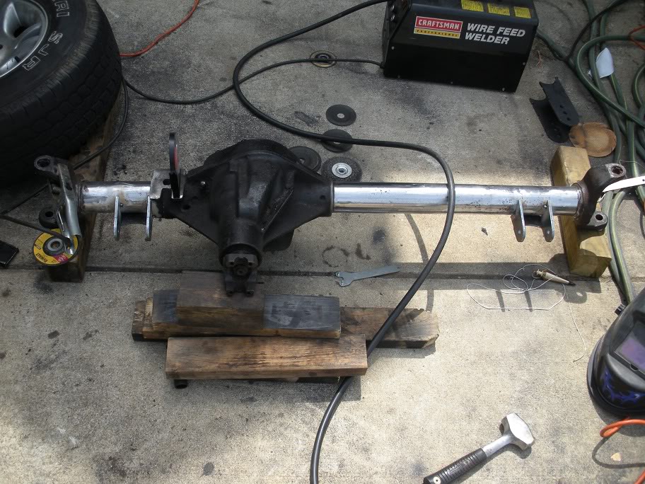
So to start, I cut off all the brackets that were previously welded to the axle housing, grinded it all smooth and flap wheeled the axle to give a good welding surface. Here is the axle prepped and ready for the new brackets...
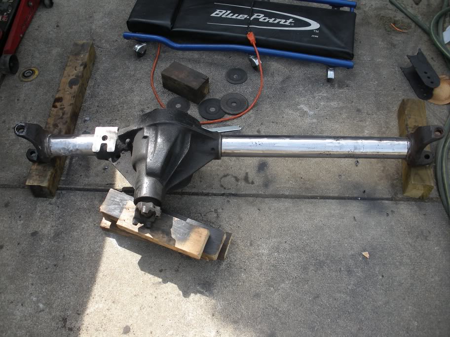
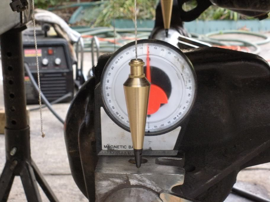
With the axle clean, I decided to start with the 2 lower link brackets since they are the easiest to set up. We made sure the axle was level by placing an angle finder on the leaf spring perch that is cast into the diff pumpkin and making sure it read 0. This could have been done with a level, but my angle finder has a magnetic base to keep it in place. My line of thought on leveling the axle is even with the 4-6 degrees of caster that the axle must later be turned for, it will still keep the lower link brackets in a good location, and its easier to keep the axle still when its sitting level! So to locate the lower link brackets, I decided the best spot to place them was as far in on the drivers side as the pumpkin would allow with the passenger side matching the distance inward. I did this because it still keeps the lower links outside the frame rails but gives me as must tire clearance as I can. So using a level on the bridge of the lower link bracket, we placed the bracket against the pumpkin and rotated it so the bridge was level. We did it this way to make it very easy to equal on the other side.
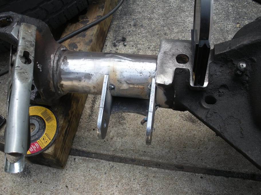
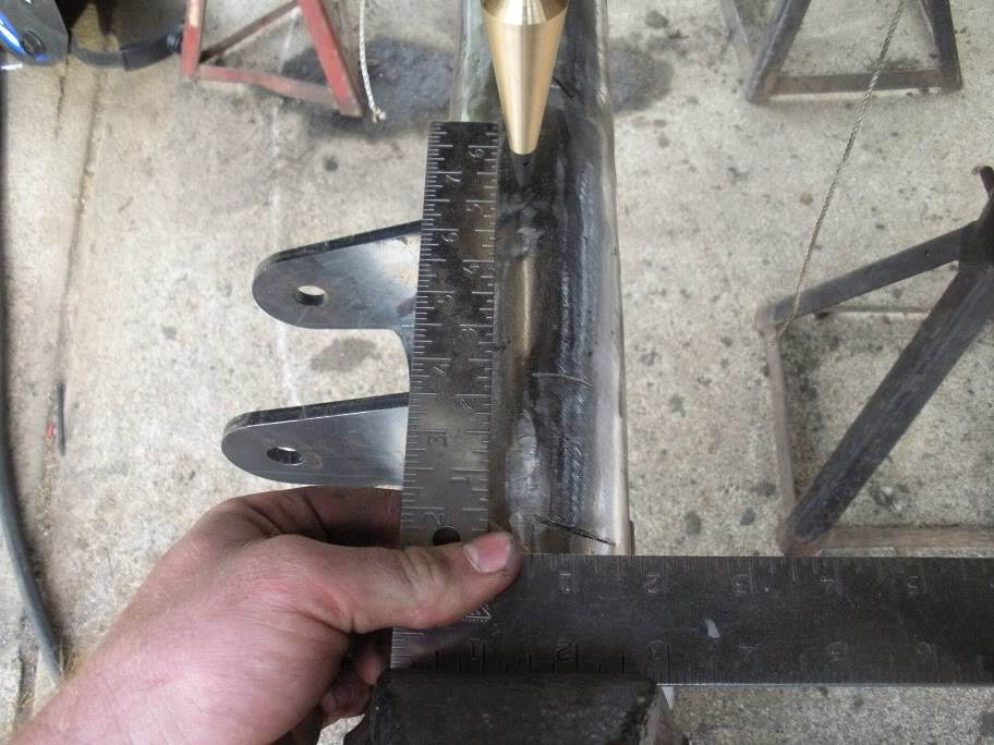
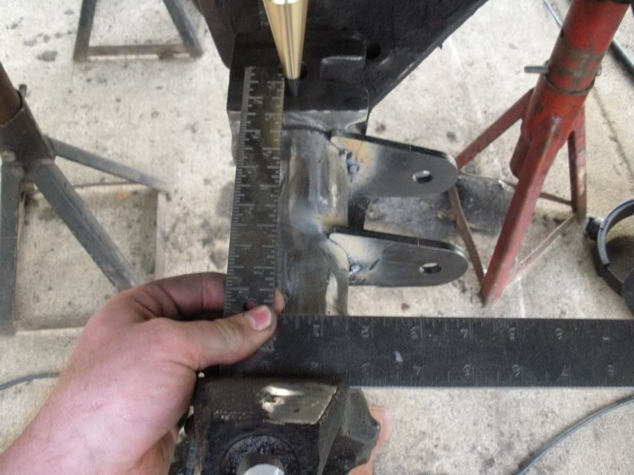
So with the first bracket tacked in place, I measured how far in it was from the knuckle "C" bracket...
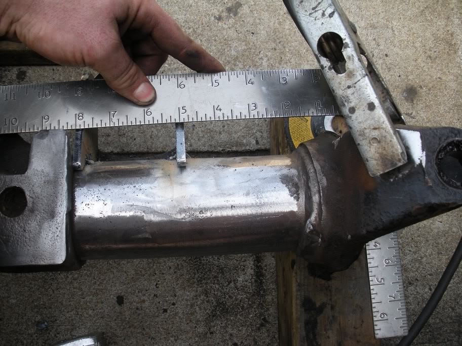
And I measured the other side to locate the passenger side bracket equally from the knuckle "C" bracket and marked the axle...
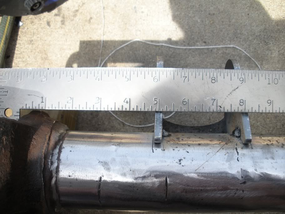
Keeping the bracket within the marks, we rotated it until the bridge of the bracket was level like the other side... this ensured they were placed equally distanced in and equally angled.
So to start, I cut off all the brackets that were previously welded to the axle housing, grinded it all smooth and flap wheeled the axle to give a good welding surface. Here is the axle prepped and ready for the new brackets...
With the axle clean, I decided to start with the 2 lower link brackets since they are the easiest to set up. We made sure the axle was level by placing an angle finder on the leaf spring perch that is cast into the diff pumpkin and making sure it read 0. This could have been done with a level, but my angle finder has a magnetic base to keep it in place. My line of thought on leveling the axle is even with the 4-6 degrees of caster that the axle must later be turned for, it will still keep the lower link brackets in a good location, and its easier to keep the axle still when its sitting level! So to locate the lower link brackets, I decided the best spot to place them was as far in on the drivers side as the pumpkin would allow with the passenger side matching the distance inward. I did this because it still keeps the lower links outside the frame rails but gives me as must tire clearance as I can. So using a level on the bridge of the lower link bracket, we placed the bracket against the pumpkin and rotated it so the bridge was level. We did it this way to make it very easy to equal on the other side.
So with the first bracket tacked in place, I measured how far in it was from the knuckle "C" bracket...
And I measured the other side to locate the passenger side bracket equally from the knuckle "C" bracket and marked the axle...
Keeping the bracket within the marks, we rotated it until the bridge of the bracket was level like the other side... this ensured they were placed equally distanced in and equally angled.
Last edited by 95_318SLT; 05-11-2010 at 07:26 PM.
#7
03-18-2010, 07:35 PM
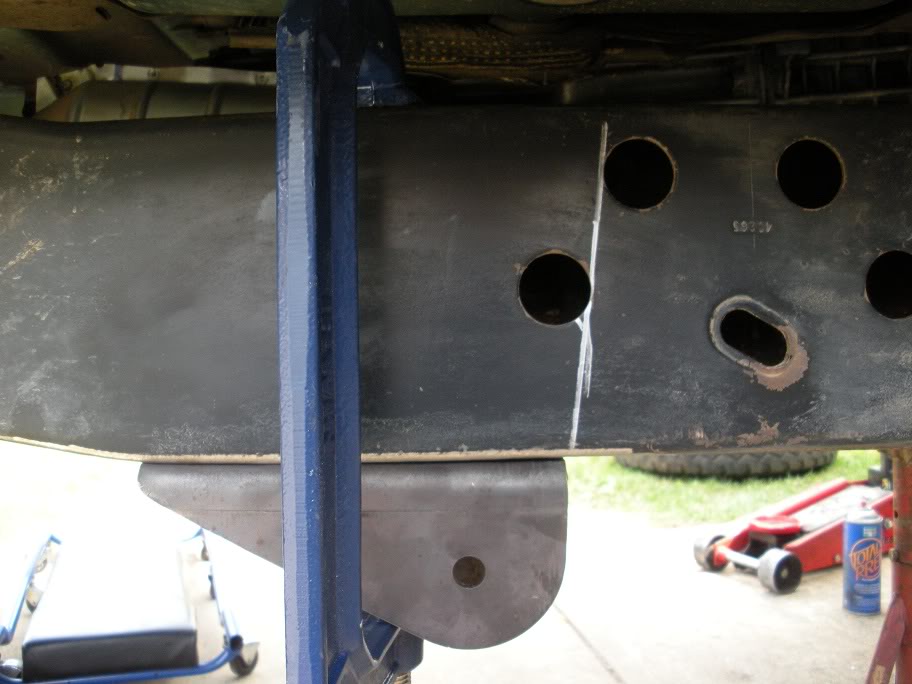
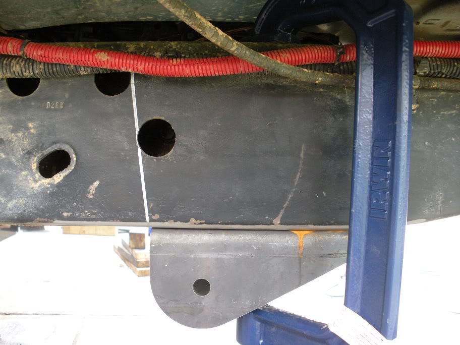
So now the frame side lower link brackets need to be placed. I decided the best place to locate them was under and slightly behind the transmission crossmember bolt holes in the frame rail where the frame is flat. I pushed it as far back as it could go to make my links as long as possible. Any closer and the links would have to get shorter... shortening the radius of the links, and any further back and the frame would get in the way!
So we started by grinding the bottom of the frame rails smooth to give as flat of a mounting surface as possible and flap wheeled it to give a good welding surface. Then, I held the mount up in place to look for the best way to measure it to make both sides equal. What I decided to do was draw a line that was tangent to the two rear crossmember bolt holes, knowing they are the same on both sides! It worked out well for placing the brackets. So with that line drawn, we used flat plates and 8 inch C-Clamps to line the brackets with the outside edge of the frame rails, and clamp them in place for tack welding.
Passenger's Side...
Driver's Side...
Last edited by 95_318SLT; 05-11-2010 at 07:28 PM.
Trending Topics
#8
03-19-2010, 04:12 PM
So with all 4 lower link brackets in place, it was time to put the axle back under the truck to measure out for the links. So we slid the axle under the truck and centered it. To do this, we located the center of each wheel well and hung a plumb bob from each frame rail equally. We measured from the knuckle "C" brackets in to the plumb bobs on each side and moved the axle side-side until it was centered. Then we eyed the plumb bobs and move the axle front-back until it the plumb bobs were pointing at the middle of the axle tubes.
So with all the lower link brackets tacked in place, and the axle centered under the truck and at the height the tires would put them at, we double checked everything we had done so far by measuring each pair of mounts eye to eye and they were exactly even!!!!!!!! Whew!
So with the axle sitting in place, we picked an initial length of how far up the threads to place the johnny joints in the bungs. This is important because if the johnny joints need to be threaded out to make the links longer, they need to have plenty of thread still holding them, but they also need room to thread in in cast the links need to be made shorter! Then we hung them from each mount and measured bung to bung to find a tube length, cut the tubes, and placed everything together.
Last edited by 95_318SLT; 04-03-2010 at 08:51 PM.
#9
04-03-2010, 08:49 PM
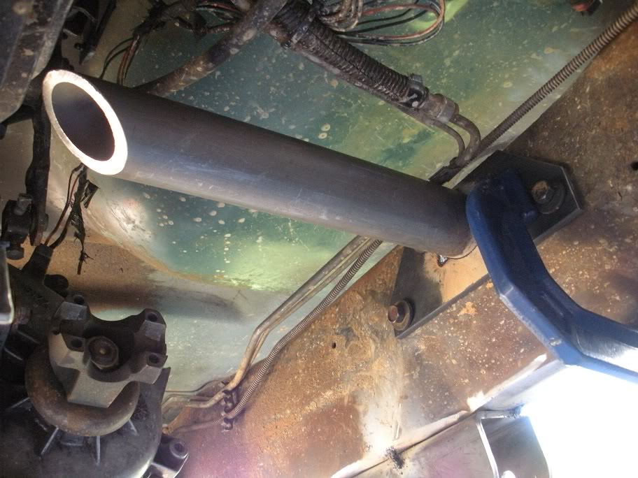
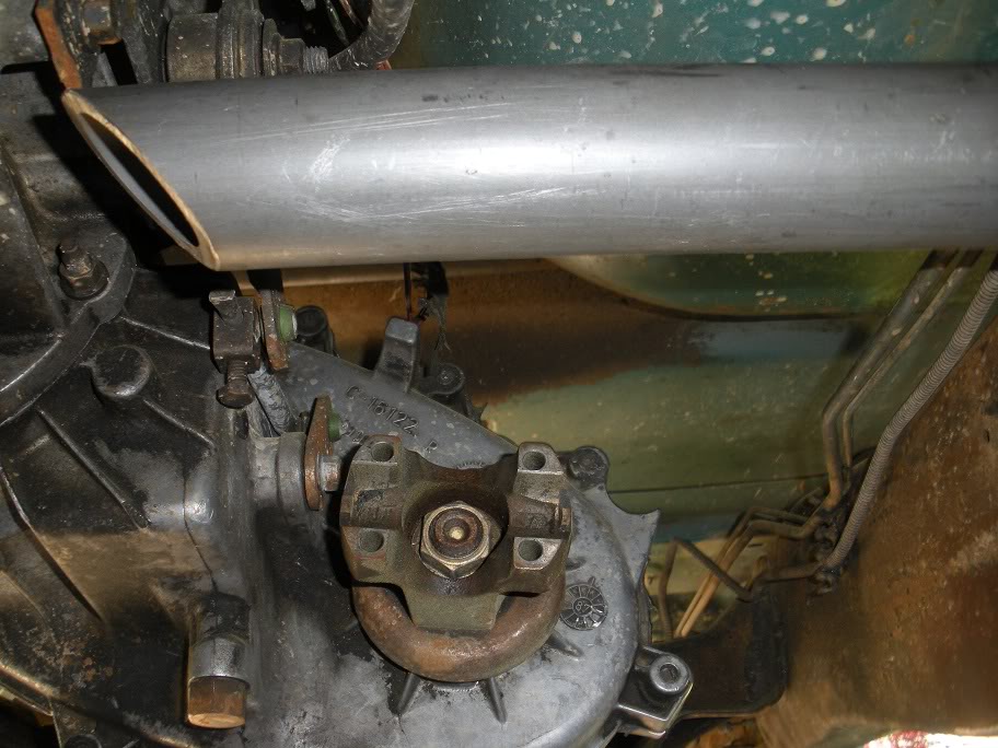
Well I didn't really get into it today with it being Easter and all, but I did some measuring trying to find the best place to put the upper link. I realized the passenger side engine-to-transmission-to-axle bracket is in the way of placing the upper link, so I went ahead and took care of it today.
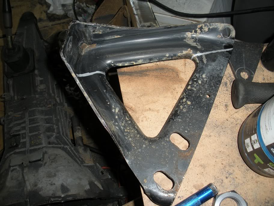
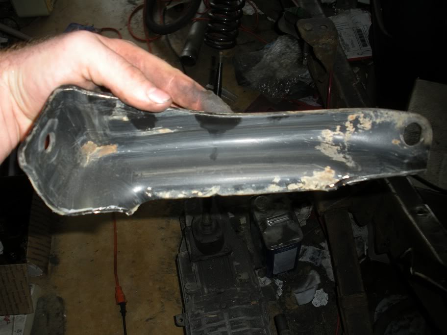
But here is the quick run-down of modifying that bracket... I knew that bracket would have to be taken care of a while ago when I realized how far it stuck down, but I was putting it off trying to think of the best way to deal with it. Then, yesterday, when Sheriff420 was over here helping me out I took a look under his 4x4 5.2 Ram that came from the factory with a solid front axle to see what they used for a bracket under them. All that bracket was on his truck was a strip with a bolt at each end that had bends in it for rigidity... easy enough to mimick!! So what I did was took it out, cut the top strip off, sprayed some paint over the cut, and put it back on!
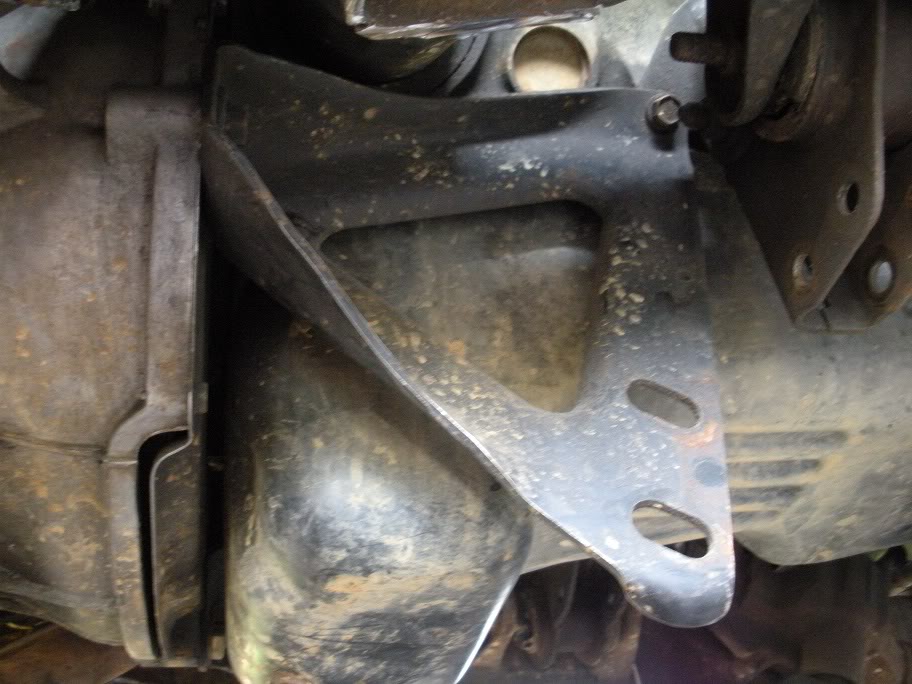
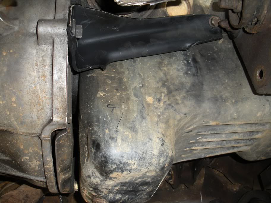
I'm still deciding if I should do the same thing on the other side, but I'll hold off on it for now becuase its not in the way of anything.
But here is the quick run-down of modifying that bracket... I knew that bracket would have to be taken care of a while ago when I realized how far it stuck down, but I was putting it off trying to think of the best way to deal with it. Then, yesterday, when Sheriff420 was over here helping me out I took a look under his 4x4 5.2 Ram that came from the factory with a solid front axle to see what they used for a bracket under them. All that bracket was on his truck was a strip with a bolt at each end that had bends in it for rigidity... easy enough to mimick!! So what I did was took it out, cut the top strip off, sprayed some paint over the cut, and put it back on!
I'm still deciding if I should do the same thing on the other side, but I'll hold off on it for now becuase its not in the way of anything.
Last edited by 95_318SLT; 05-11-2010 at 07:32 PM.
#10
04-04-2010, 06:56 PM
So I've been waiting all week for some brackets to get here, and in the meantime, I've been working on building a custom transmission mount crossmember. There are two reasons this must be done for a 3 link SAS... the crossmember is in the way of the upper link on the passenger side, and in the driveshaft on the drivers side. I didn't get any before pics, but all of ya'll know what the factory crossmember looks like!
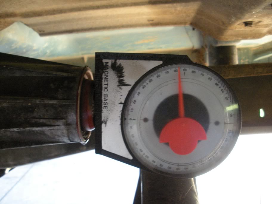
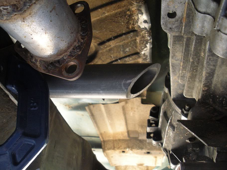
So the idea is to get the crossmember up, out of the way. Important: measure the output shaft angle before you start so you know where the transmission needs to sit when you're done!! I had enough DOM tubing left from what I ordered for my links that I went ahead and used it. First, I made a plate to mount to each frame rail. The frame at the transmission crossmember mounts is at a 10 degree angle, so the first length of tube needs to come down at a 10 degree angle. Then, its all 90 deg angles after that!
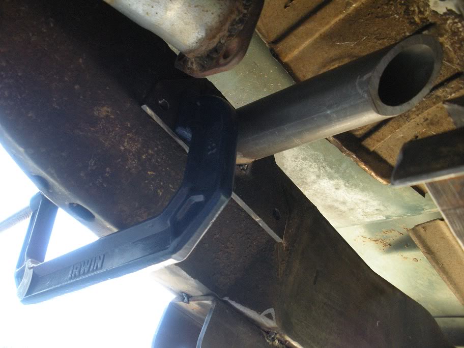
DSCN0796-1.jpg?t=1271476389
So as you can see in the above picture, I hacked up the factory crossmember to get the mounting plate! The next step is to drop 2 tubes down to where they meet the bottom of that plate.
So the idea is to get the crossmember up, out of the way. Important: measure the output shaft angle before you start so you know where the transmission needs to sit when you're done!! I had enough DOM tubing left from what I ordered for my links that I went ahead and used it. First, I made a plate to mount to each frame rail. The frame at the transmission crossmember mounts is at a 10 degree angle, so the first length of tube needs to come down at a 10 degree angle. Then, its all 90 deg angles after that!
DSCN0796-1.jpg?t=1271476389
So as you can see in the above picture, I hacked up the factory crossmember to get the mounting plate! The next step is to drop 2 tubes down to where they meet the bottom of that plate.
Last edited by 95_318SLT; 05-11-2010 at 07:33 PM.