
DIY - 46RE Transmission Rebuild (work in progress)
#1
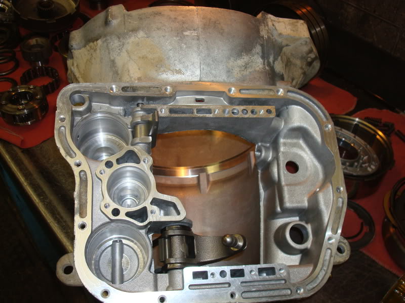
 09-15-2011, 11:42 PM

So I have decided to chronicle the rebuild of my 46re for the benefit of others who may feel capable, but maybe a little timid. It can be done if your organized and keep your workspace clean and use lint free towels. The service manual is a must have as I wont be covering the removal process. Not to mention, I could not have done this without it. There are a few tolerances that are very precise so a caliper is also a must have. I won't give a tool breakdown either, but as I come across a step, I will cover what tools I used. There are many questions I felt were left unanswered during my rebuild, so I'll try to address those to the best of my knowledge. The service manual for this truck can be downloaded from Here
With that said, constructive criticism is welcome. But please don't dog on me for the way I do things. I must admit, picture taking wasn't what was really on my mind during disassembly, so I'll try to piece together some pictures from the service manual and other websites online to fill the gap. Digital photos that aren't mine were borrowed from joels garage and jeepforum.com. I just was in a hurry to see what grenaded inside. After you have the tranny down get a nice sized work area cleaned and prepped. There are lots of parts to these units. I used small reusable tupperware dishes with lids and marked them with painters tape and a marker with the corresponding "Fig. #" drawing from the factory service manual during teardown. A digital camera is also worth its weight in gold as a picture is worth a thousand words when its time to reassemble. This is going to be a process writing this up, so please bear with me as I work 60-70 hours a week. I got my parts mostly from www.wittrans.com. Here we go...
Here the transmission is pulled and ready to be disassembled.
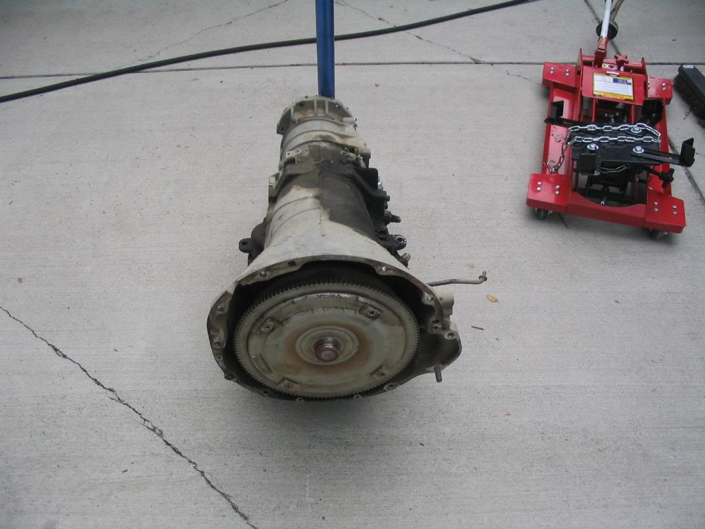
Now is a good time to clean the exterior as best as you can to prevent dirt getting in places you don't want. It also allows you to inspect the housing and external components closely.
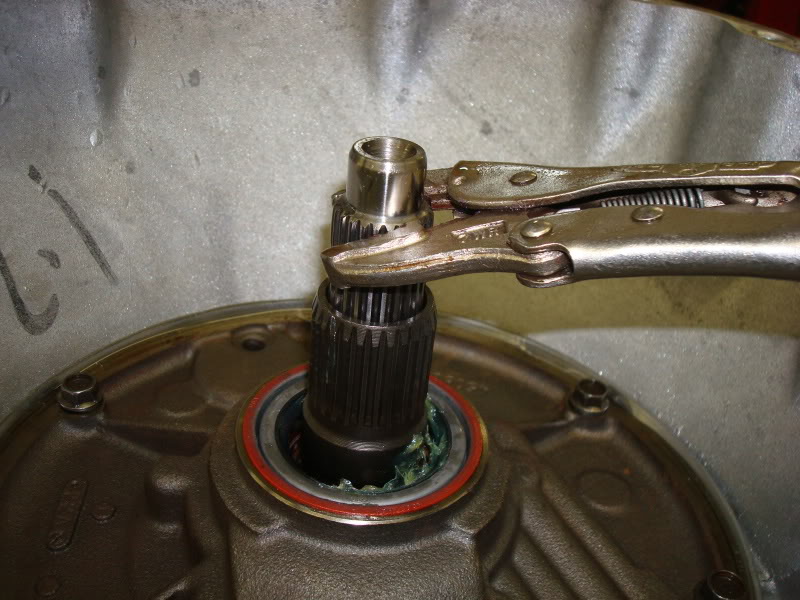
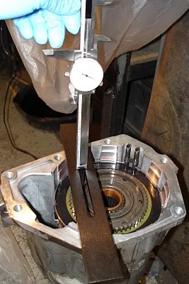
Stand the transmission up on end with the bell housing facing up. Use 4x4's under the bottom straddling the output shaft. It takes two hands so I don't have a picture of this process. You need to measure the endplay on the input shaft by grabbing it with vice grips and checking vertical movement of the shaft. Record this measurement for assembly reference.
Next you need to remove the throttle and shift levers from the valve body manual shaft and throttle lever shaft on the outside of the case. Basically the external removable linkage.
Linkage removed.
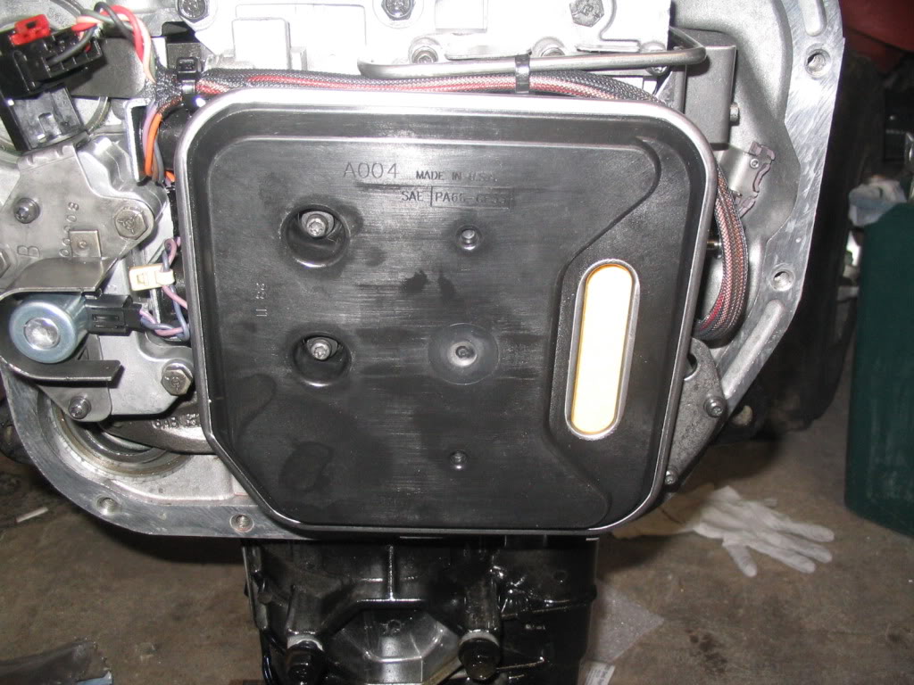
Remove the oil pan and gasket. Pan and gasket removed. The filter is already removed in this picture. It's held in place by 2 Torx-25 fasteners and these are longer than the other valve body fasteners so keep them seperate.
Here's a picture of the filter location. This is a new filter and a picture from re-assembly. But the picture serves its purpose.
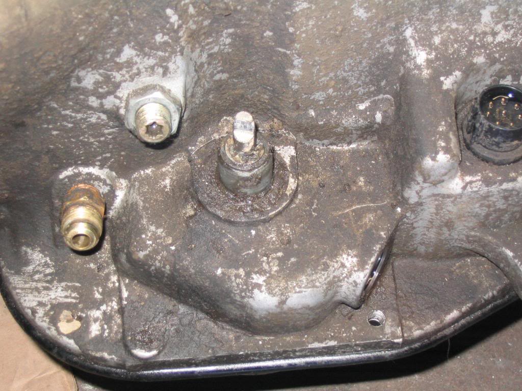
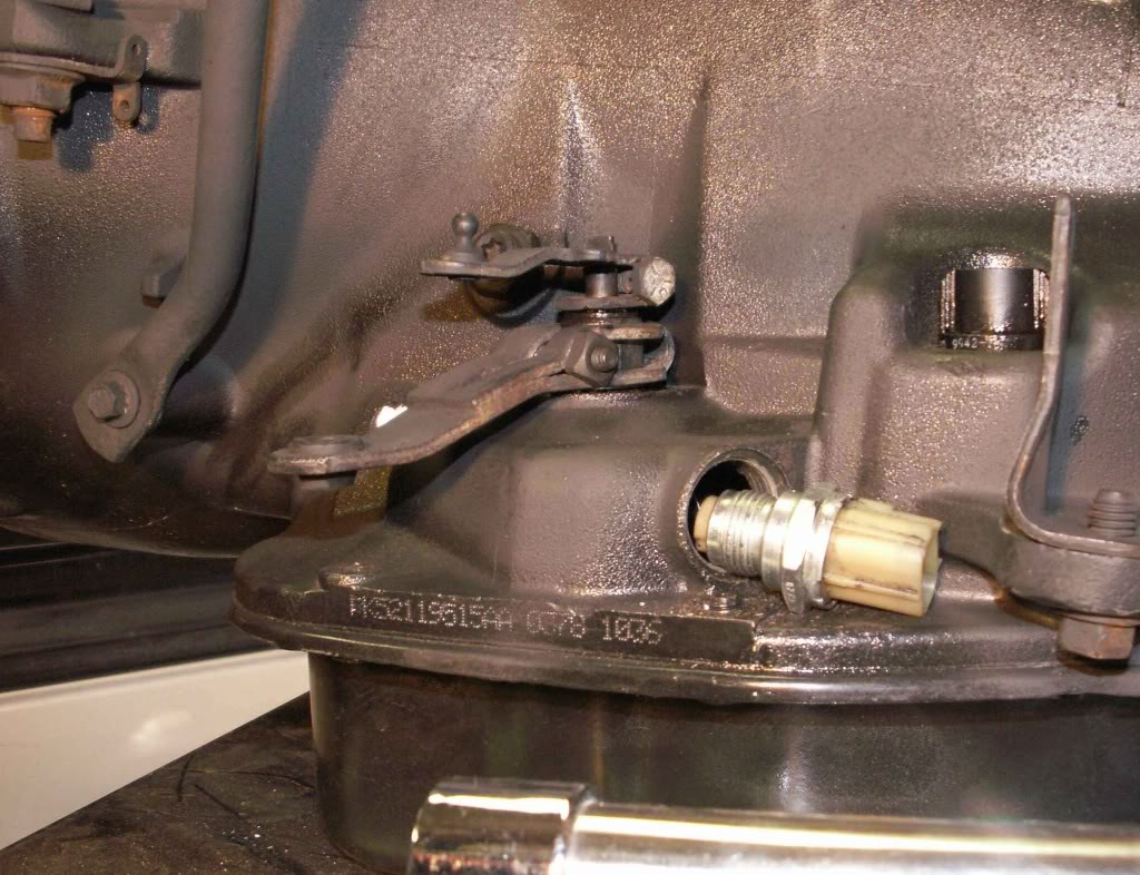
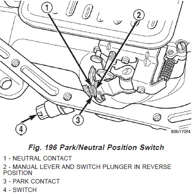
Remove the park/neutral position switch and seal. I found a 1" deep socket on my 1/2" drive ratchet works nicely.
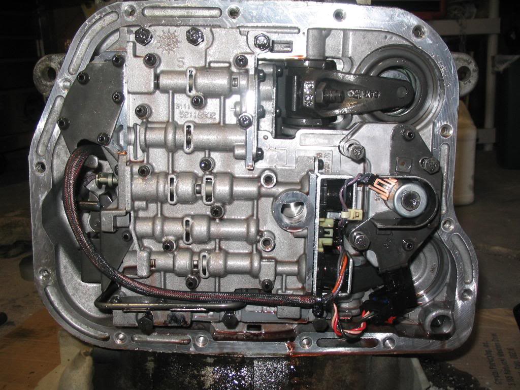
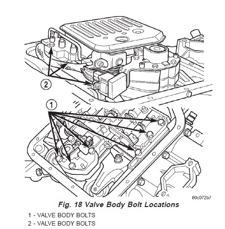
Next remove the hex head bolts attaching the valve body to the transmission case. Take note of location and length for assembly reference. There are 10.
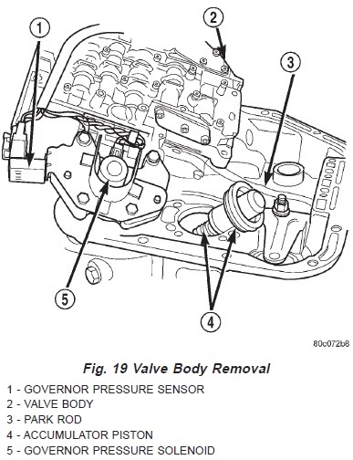
Now it's time to remove the valve body from the case. Take care not to damage the case connector that is attached to the valve body that protrudes outside the top/side of the case. It might take a very light tap or two with a rubber mallet to get it jarred loose. The parking rod will also still be attached to the valve body and is removed together. It should pull directly out of the housing. If you have trouble removing it, try turning the output shaft (the rear shaft) slightly to get the pawl to release it. Set the valve body and parking rod aside. You can also remove the accumulator piston and spring in this picture as well. I left all seals in place until it came time for reassembly to make sure I could compare old with new to make sure I had the right seals in the correct spots.
I'm going to stop here tonight. It's getting late for a work night. But I'll be back tomorrow. I'd like to keep this writeup fairly uncluttered, so please, keep the comments to a minimum until I'm finished. Sorry, I'm really not trying to sound like a jerk. Thanks guys.
Next you'll want to remove the oil seal for the pump. Use a suitable pry tool. I used a hand hook tool. It's the same seal you see above in the picture with the vice grips on the input shaft and oil pump reaction shaft.
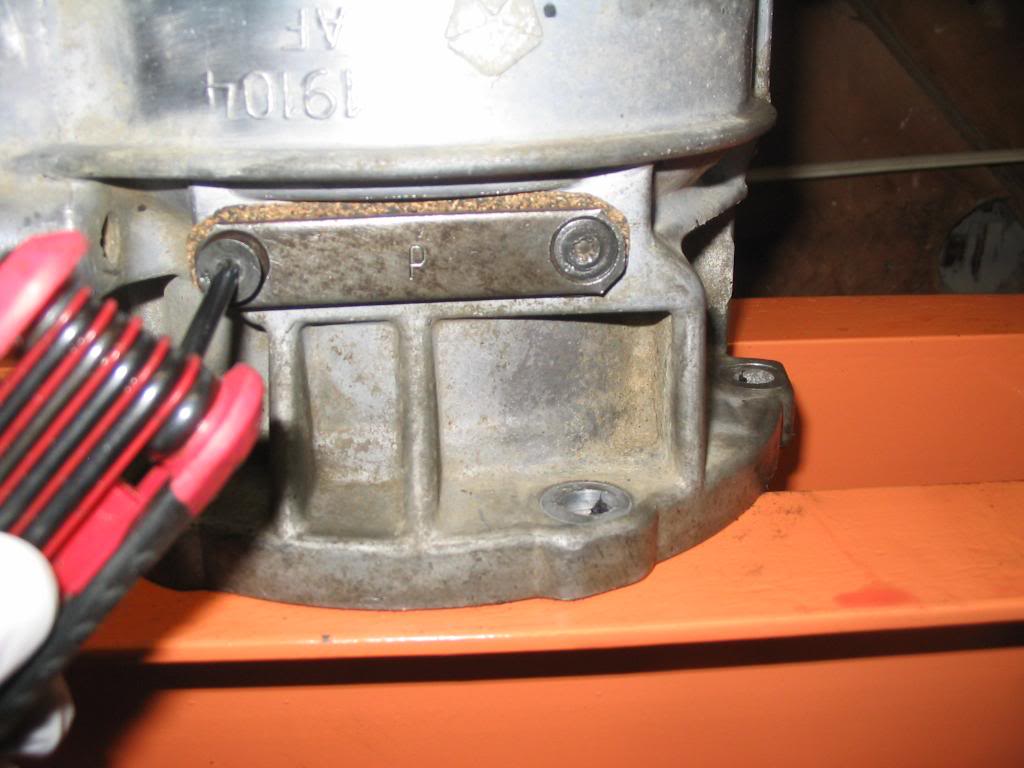
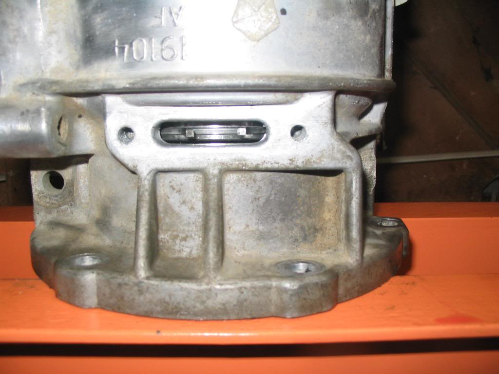
Now remove the band lever pin access cover which is basically a plug in the bell housing. A 1/4" drive extension works nicely removing this. It's in the lower left corner of this picture. Again, an install picture but it works.
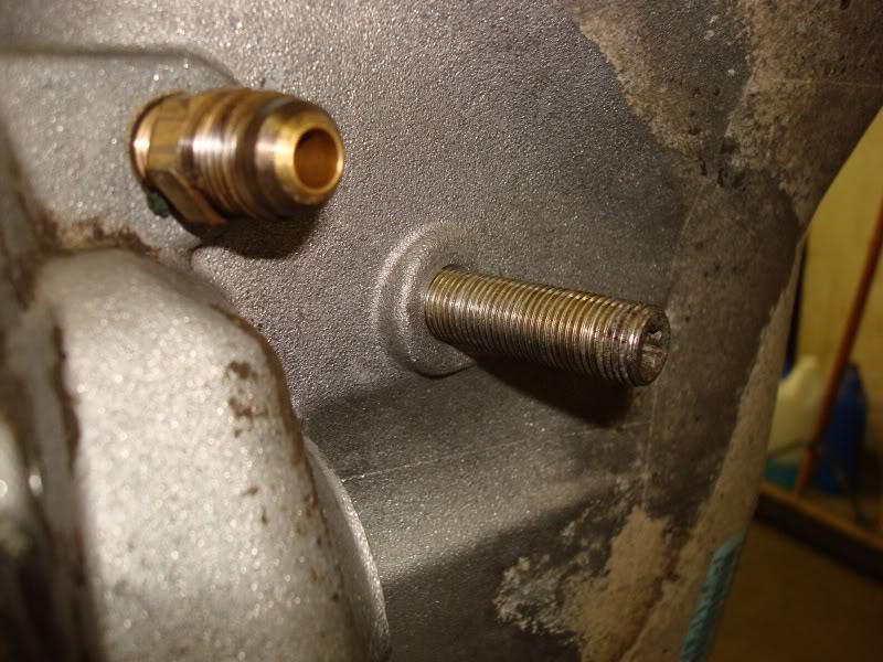
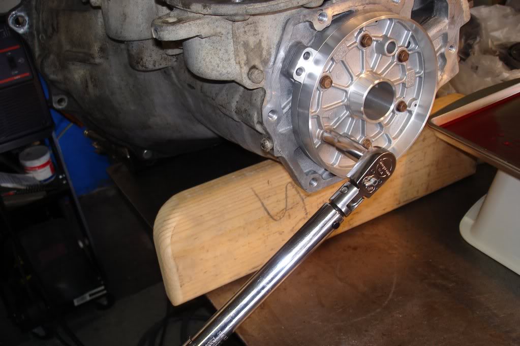
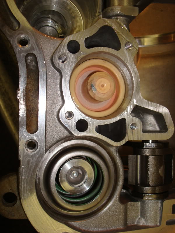
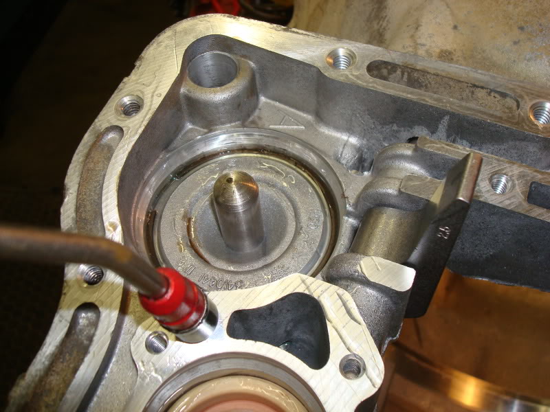
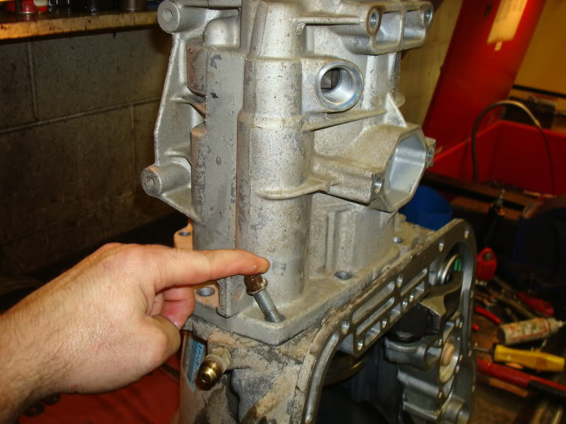
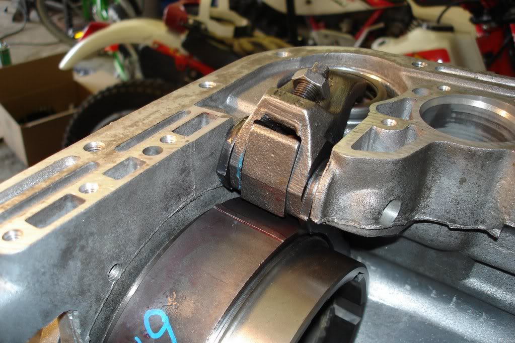
Now it's time to remove the oil pump. The picture above shows two guide pins placed through the oil pump and threaded into the transmission housing. These two particular holes are threaded on the pump housing as well, the threads are just larger. I used 2 6" pieces of 3/8" all thread installed into the threads on the pump housing. Then I put 1 3/8" washer on each piece of all thread with a nut. I used a small 30" piece of that double loop chain thats zinc plated or whatever...the cheap chain you can cut with a good pair of dikes. A couple pulls on the chain with the claw of a hammer and it popped right out. Before you remove the pump though, tighten the front band adjusting screw all the way down. The manual says to do this so you don't accidentally damage the clutches or oil pump. It's the adjuster in this picture that is a Torx-40. Loosen the adjusters locking nut, then tighten the adjuster pin all the way to the right, tightening it.
Now you can remove the pump bolts...I think theres 7. Then use the method described above to pull the pump. Behind the pump, theres a gasket. Remove that too noting its orientation for assembly.
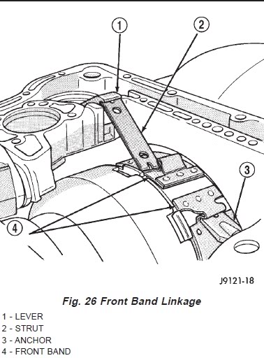
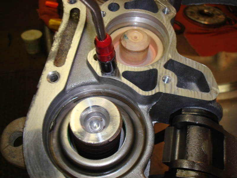
Now back the adjuster for the front band all the way off to its loosest position. Again its the Torx-40 with the locking nut. Then remove the front band strut and anchor.
Adjuster.
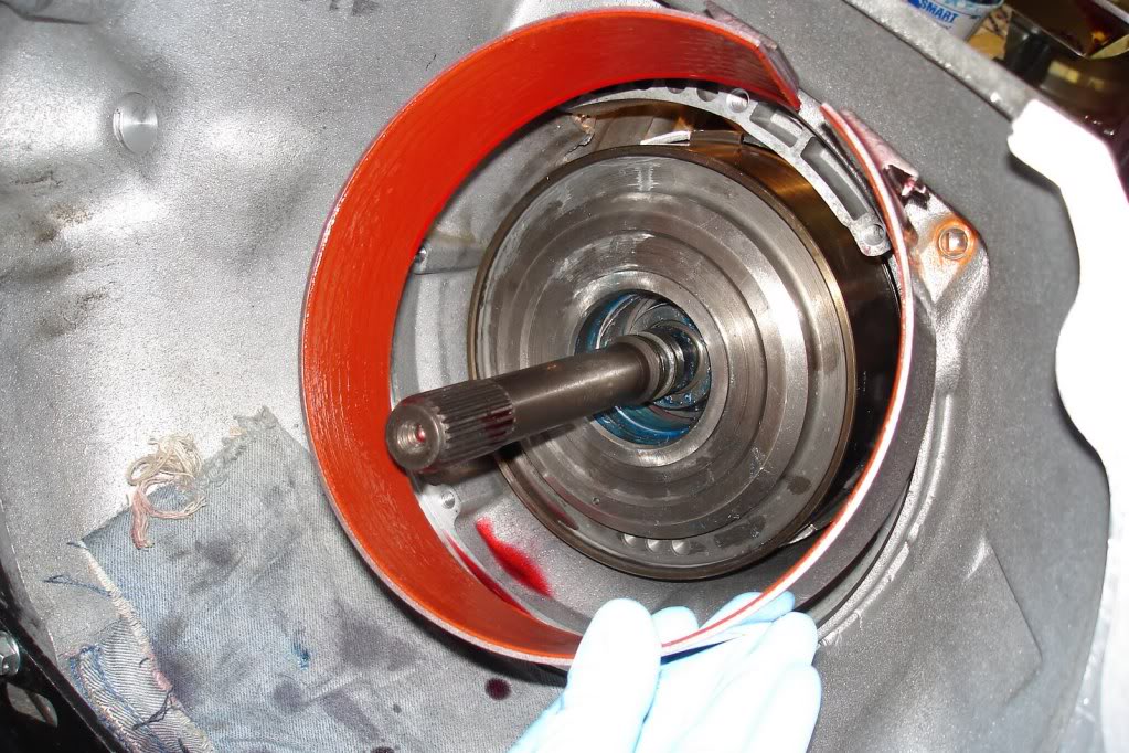
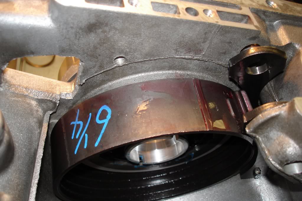
Now squeeze the tabs on the front band together and wiggle it out through the front of the bell housing. The tabs prevent you from being able to just remove it easily. You will have to rotate the band around the clutch drum to remove one tab at a time.
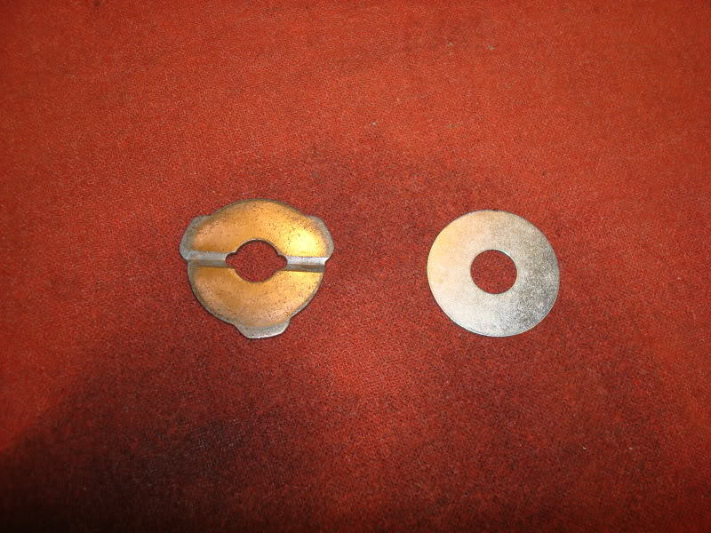
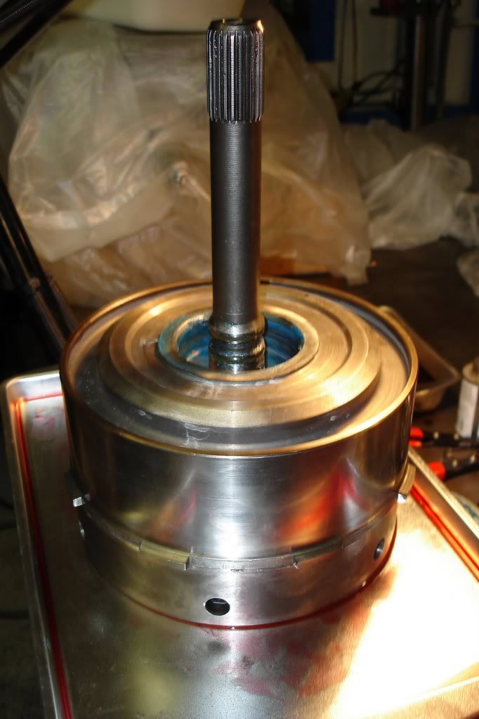
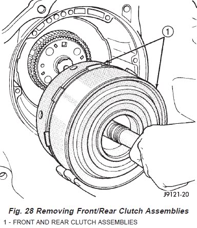
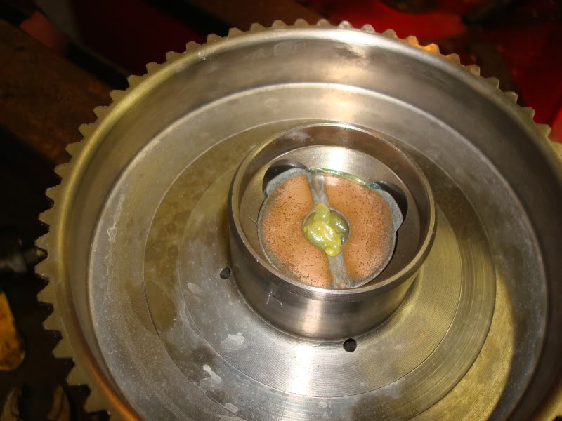
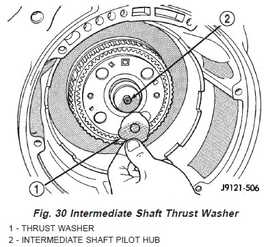
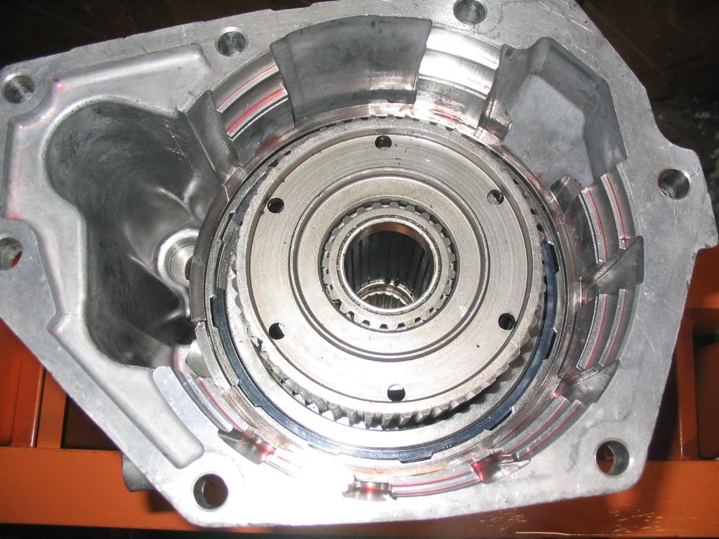
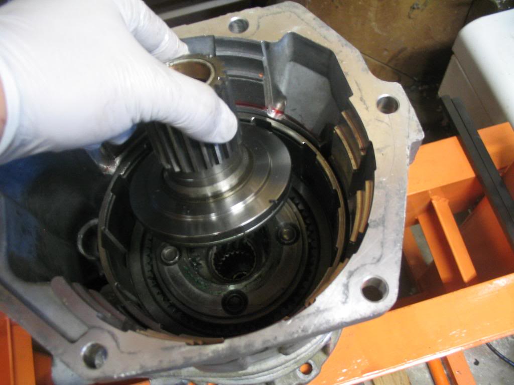
Next you'll grab the input shaft with one hand and the front and rear clutch assemblies with your other hand and work them out of the housing as an assembly. There will be two small washers sitting between the intermediate shaft and input shaft when you remove the clutches. One sits in the input shaft and has 3 ears and only fits in the recess of the input shaft one way. The other is the thrust plate washer and it sits on the nipple of the intermediate shaft. Make note of their position and set them in a dish or baggie.
Both thrust washers removed.
Front/Rear clutches and input shaft removed.
Thrust plate location.
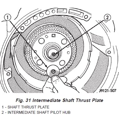
3 eared thrust washer location.
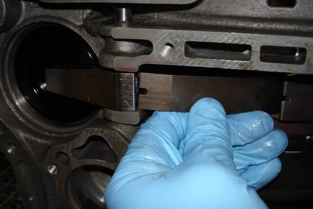
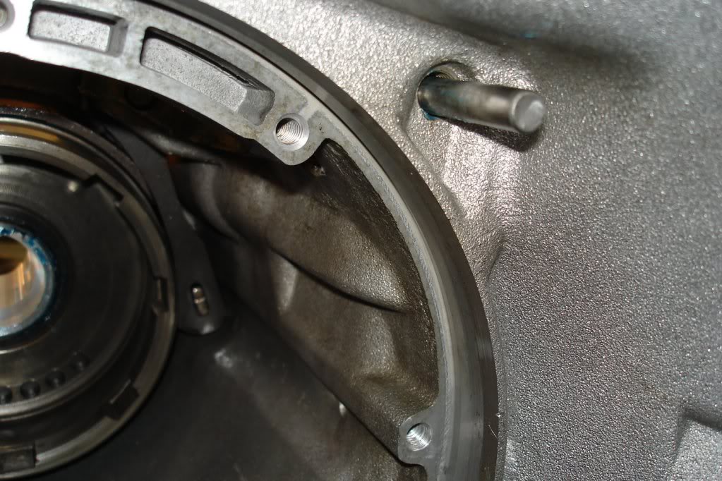
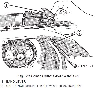
Next we'll remove the front band reaction pin and lever. A pencil magnet works good to withdraw the pin from the housing allowing the lever to be removed as well.
Front band lever pin location.
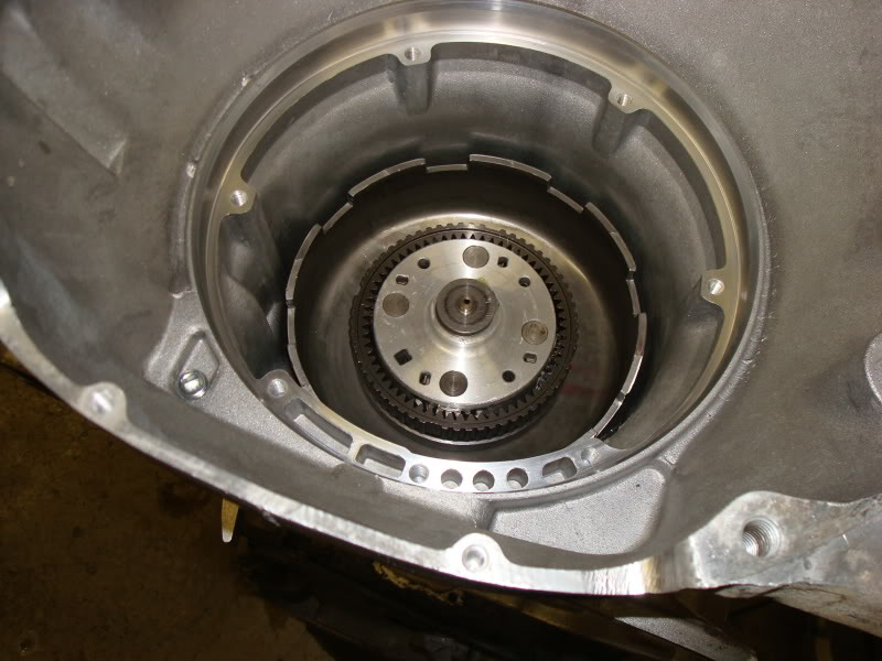
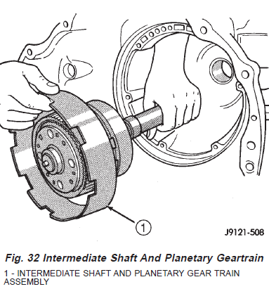
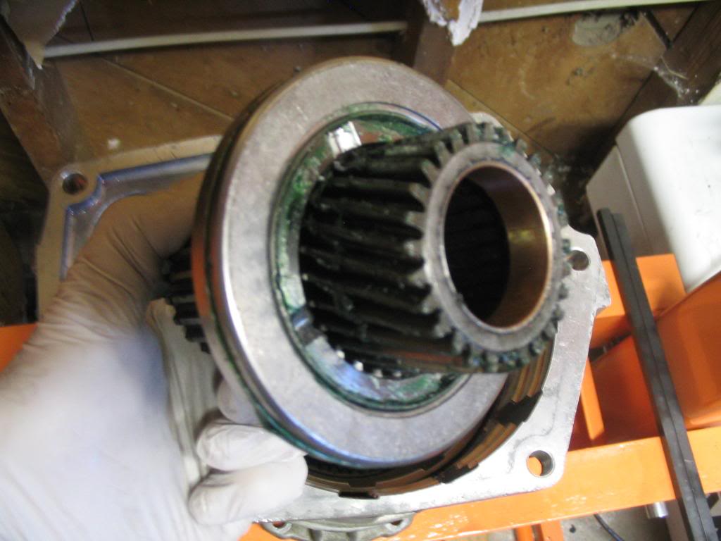
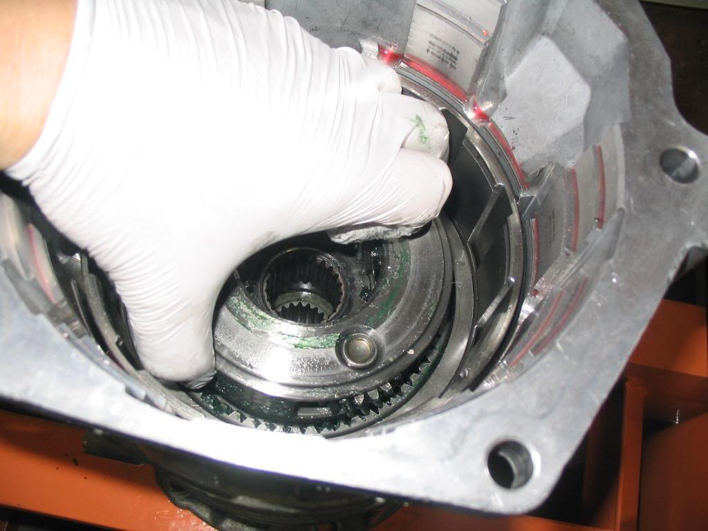
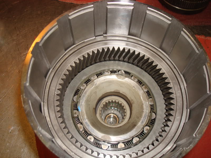
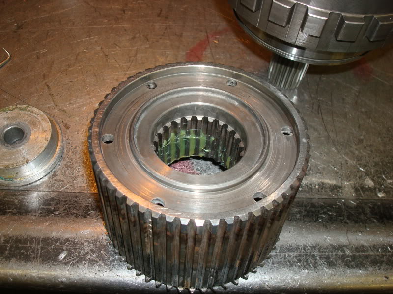
Now remove the intermediate shaft and planetary geartrain as an assembly.
Planetary geartrain and intermediate shaft location.
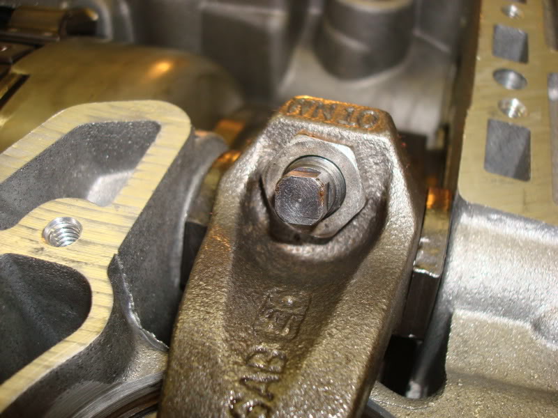
Now loosen the rear band locknut and loosen the adjuster pin 3-4 turns.
Rear band adjuster locknut and pin location.
Rear band adjuster loosened.

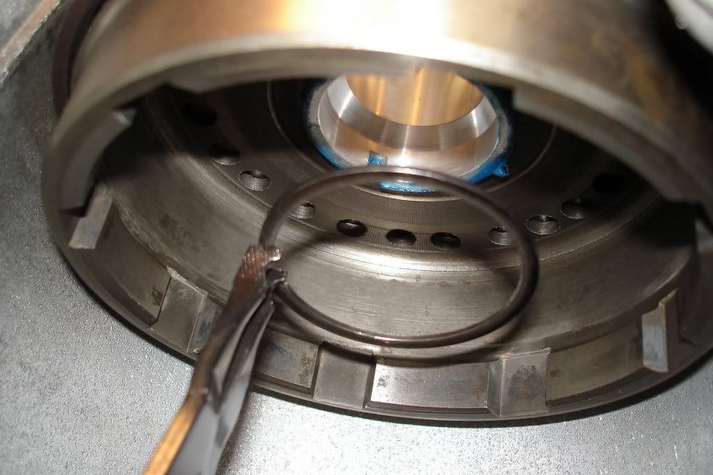
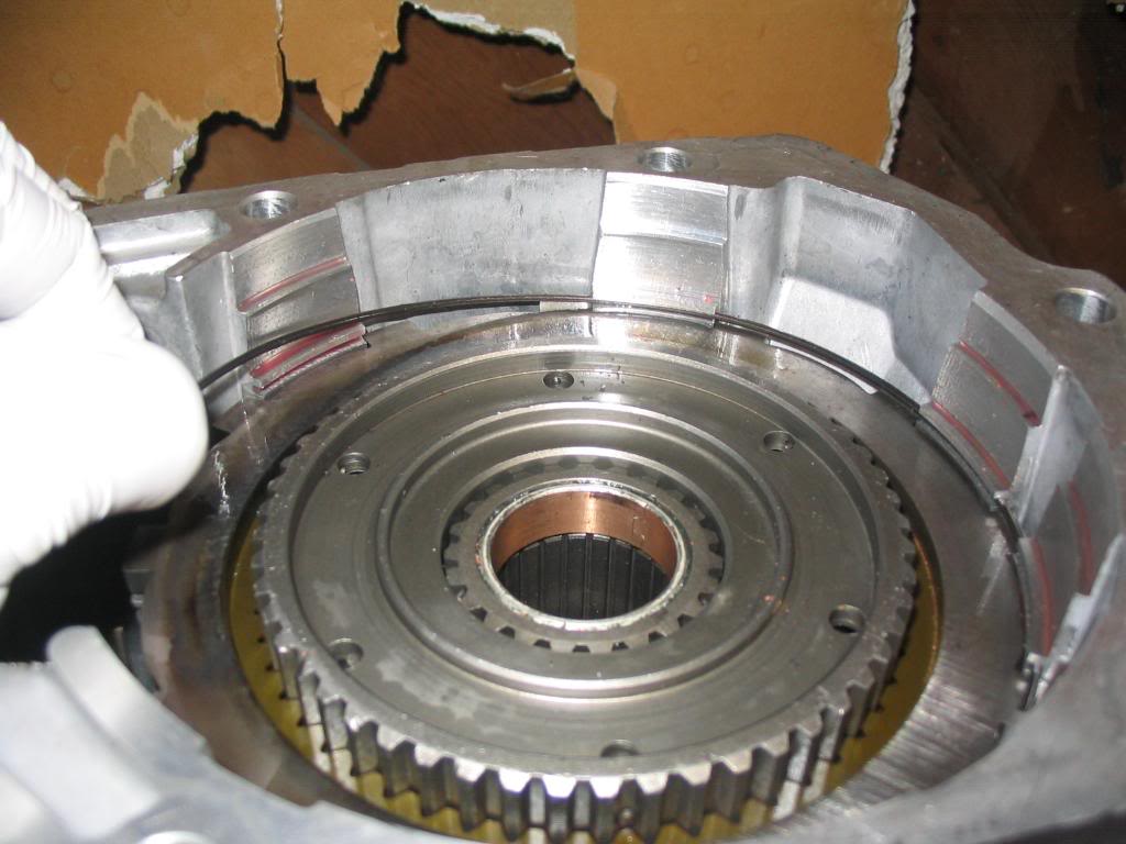
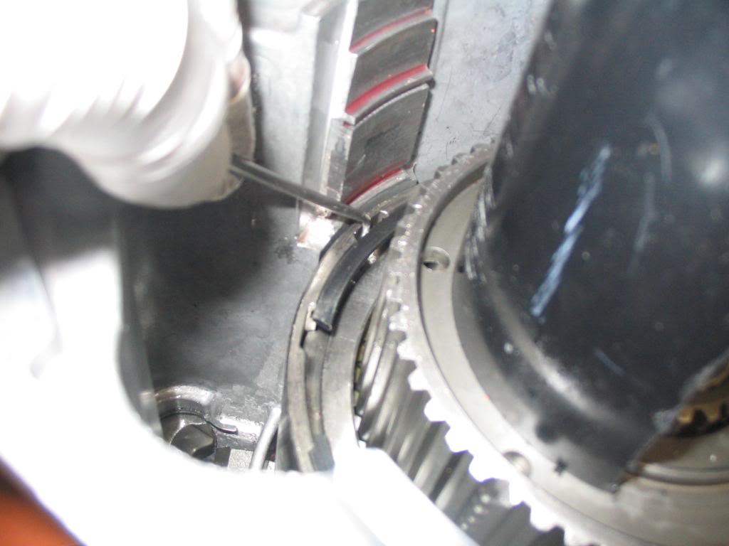
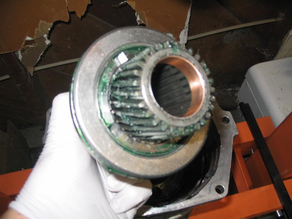
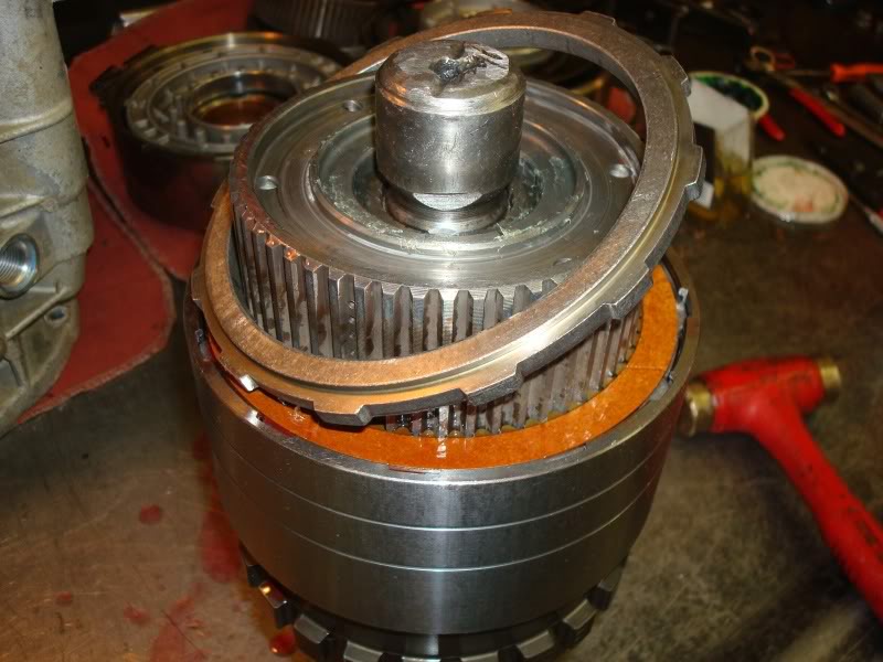
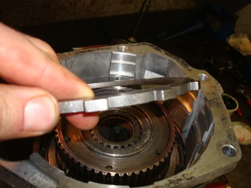
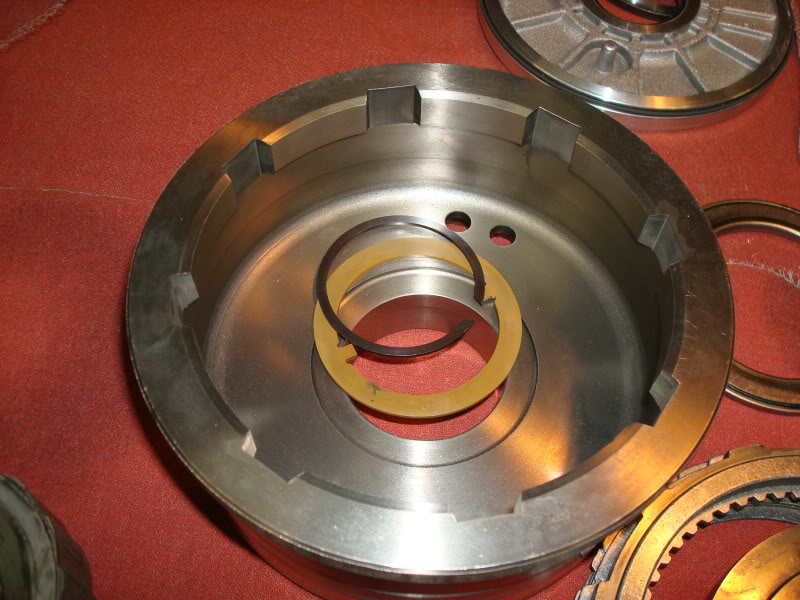
Now remove the snap ring and thrust washer from the center of the low/reverse drum and slide it forward off the O/D piston retainer hub and out of the rear band.
Snap ring location.
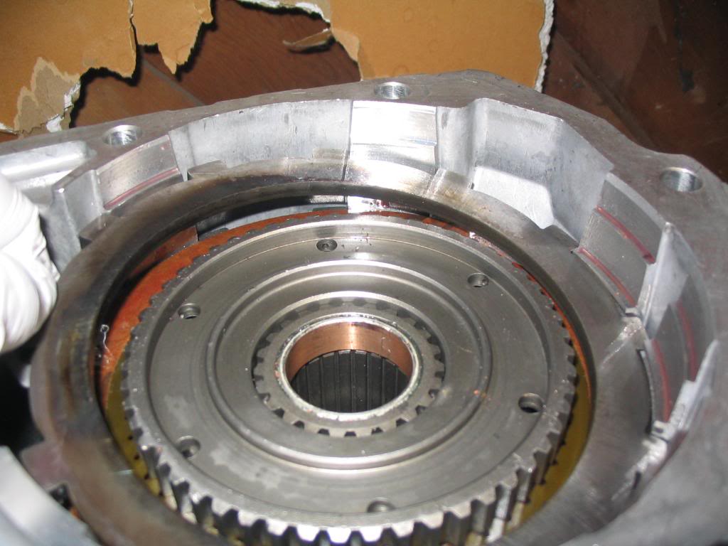
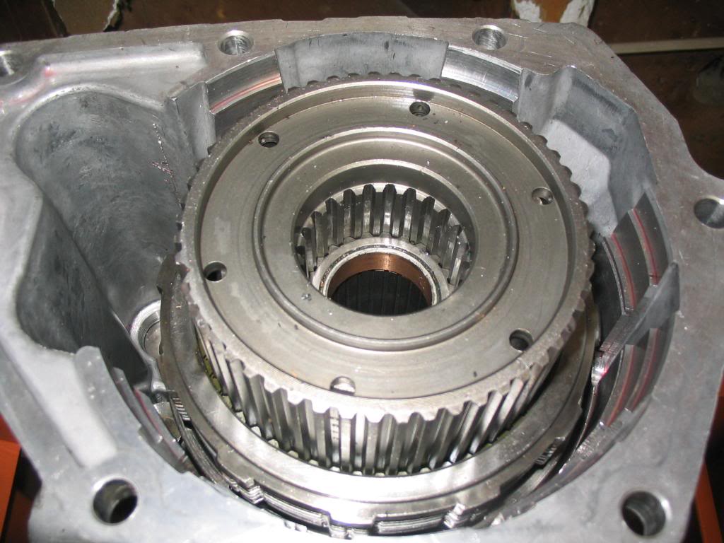
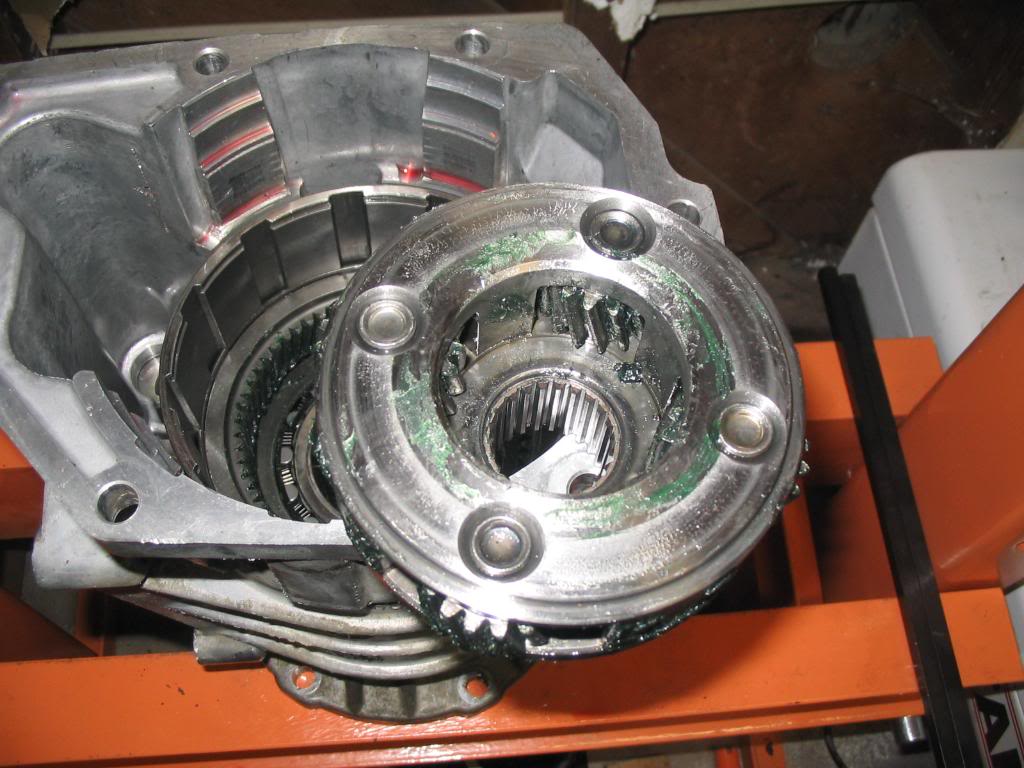
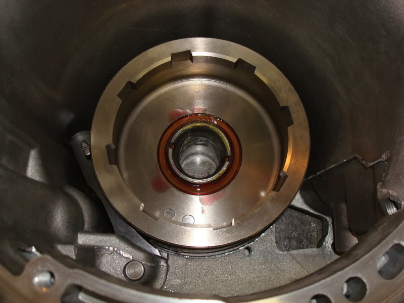
Rear drum seated on the hub.
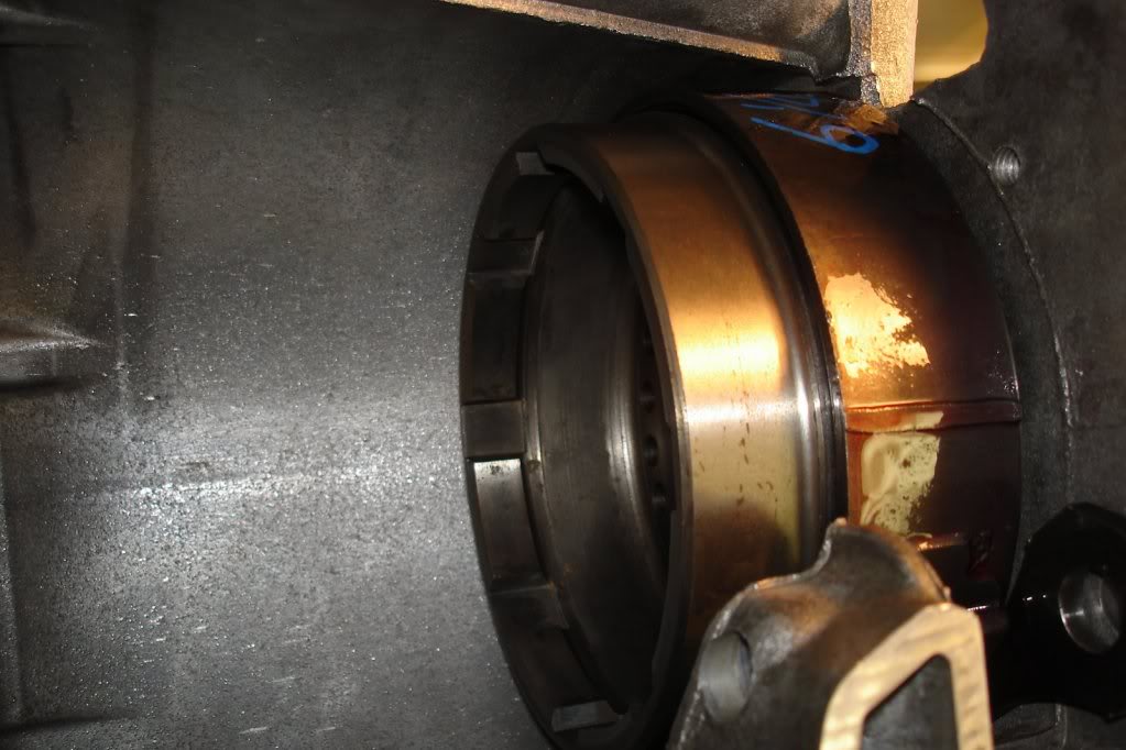
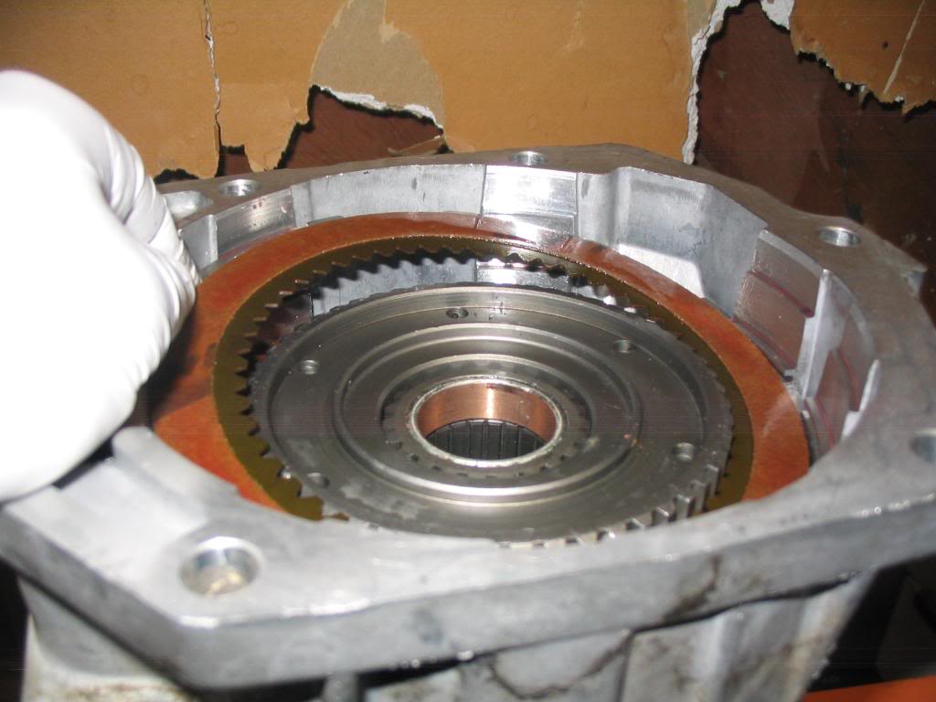
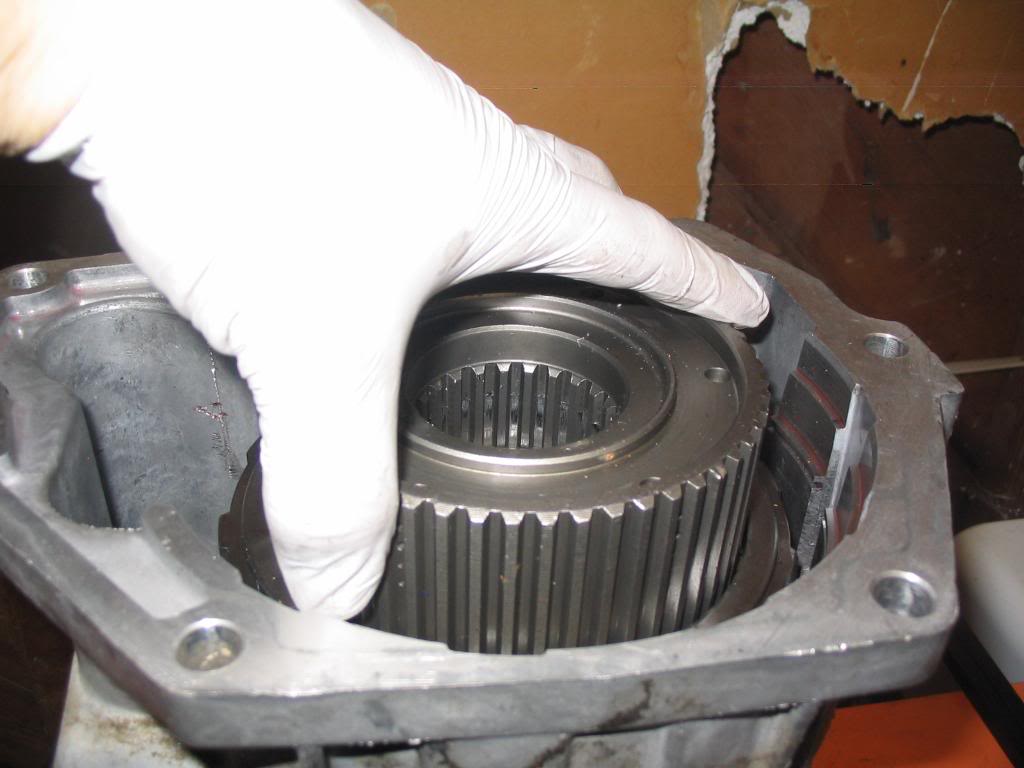
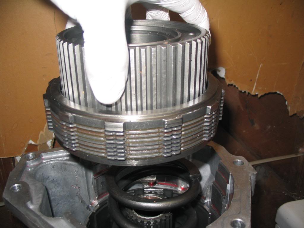
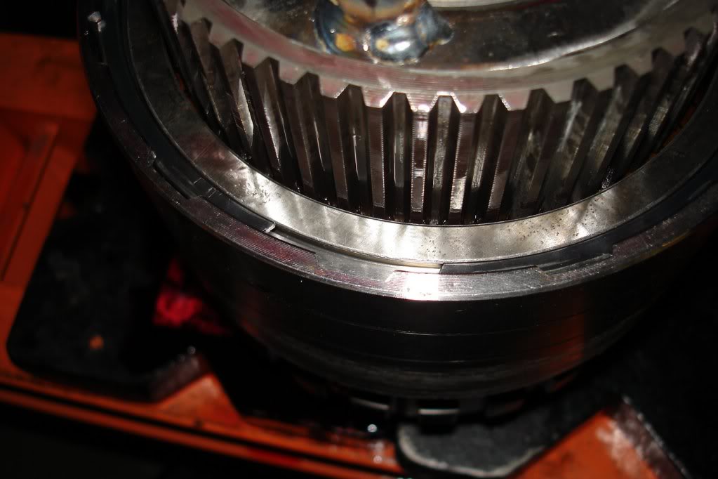
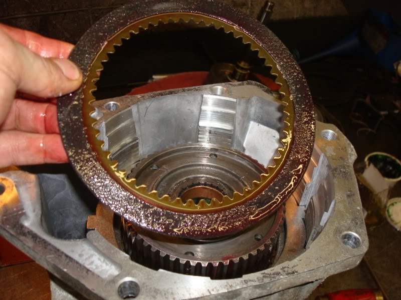
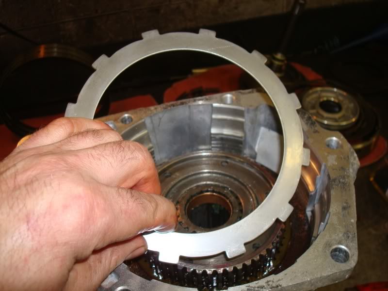
Removing the rear drum from the O/D piston retainer hub.
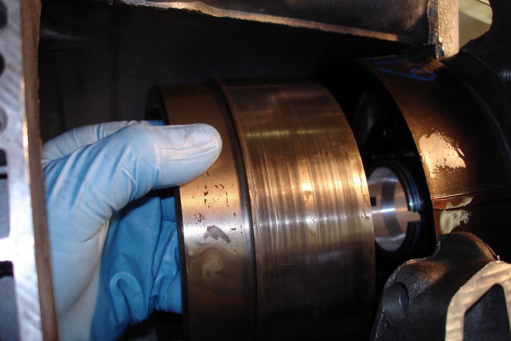
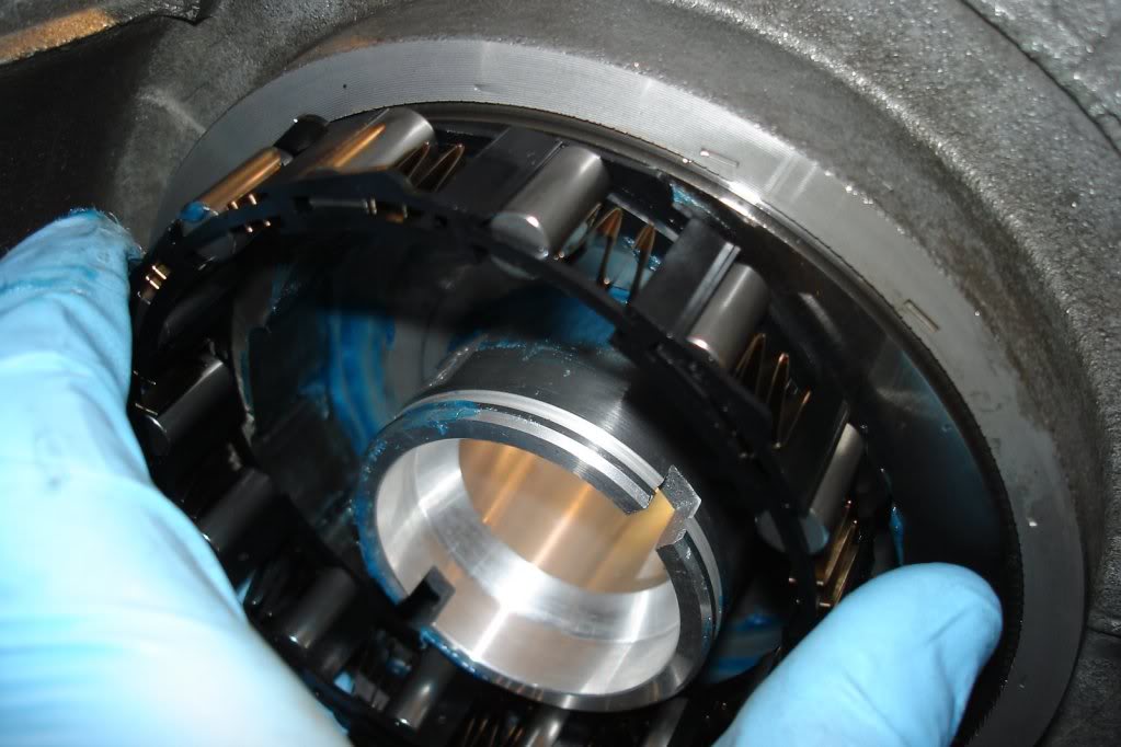
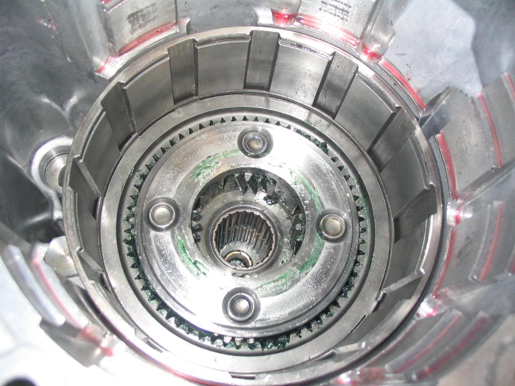
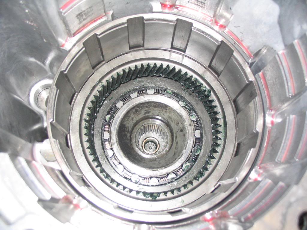
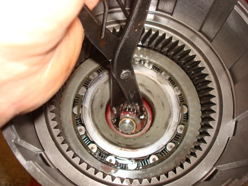
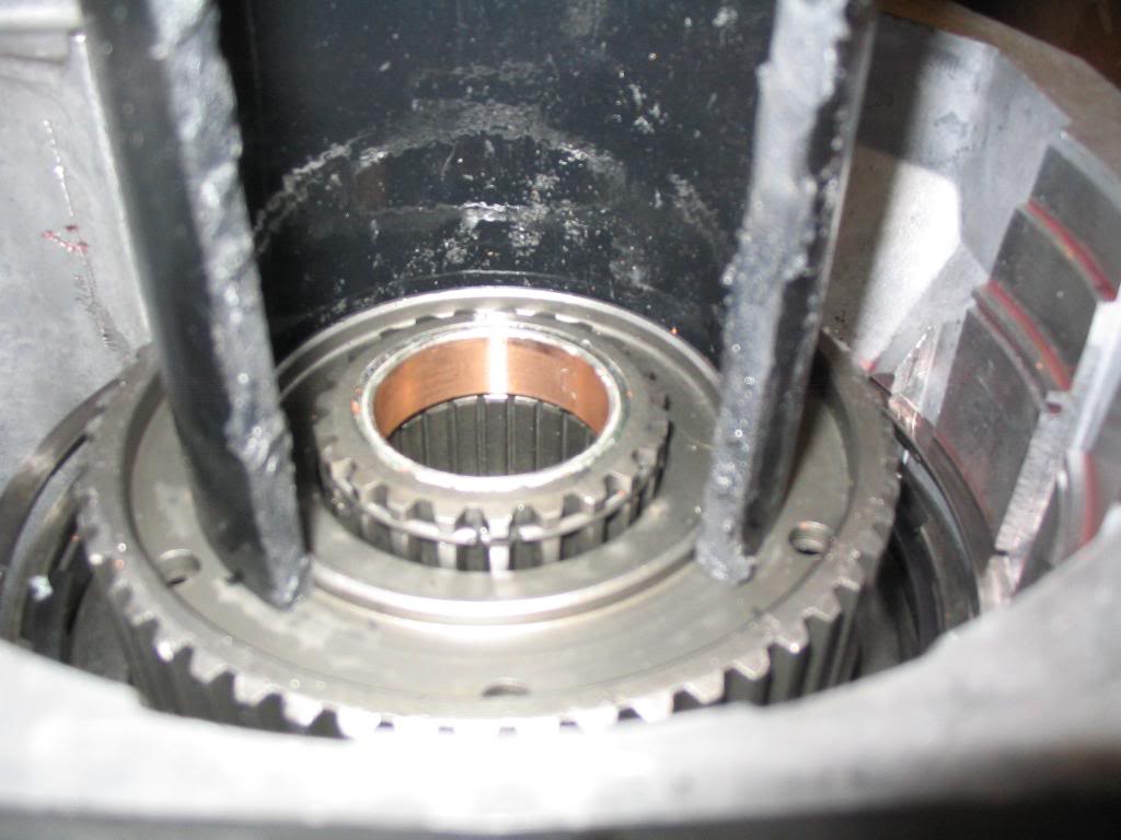
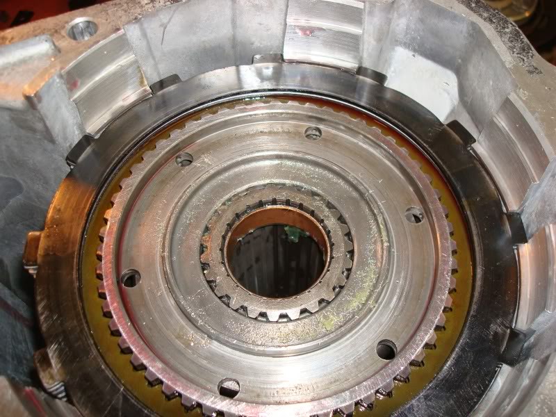
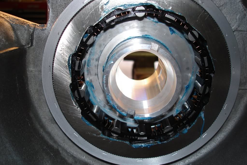
Notice the over running on way clutch assembly in the bottom of the case. This can be removed very gently so the springs and bearings don't spriong everywhere. The race is pressed into the case and should not be removed.
Over running one way clutch assembly seated in the race.

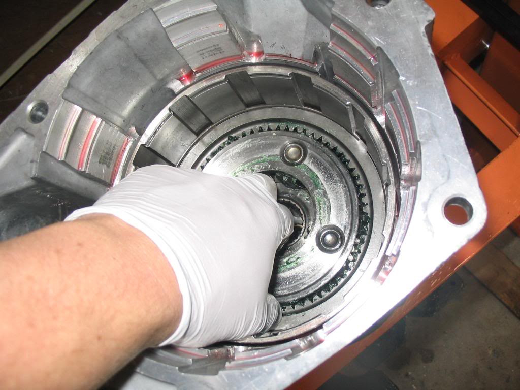
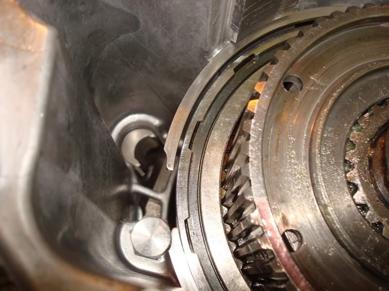
Removing the over running clutch assembly carefully.
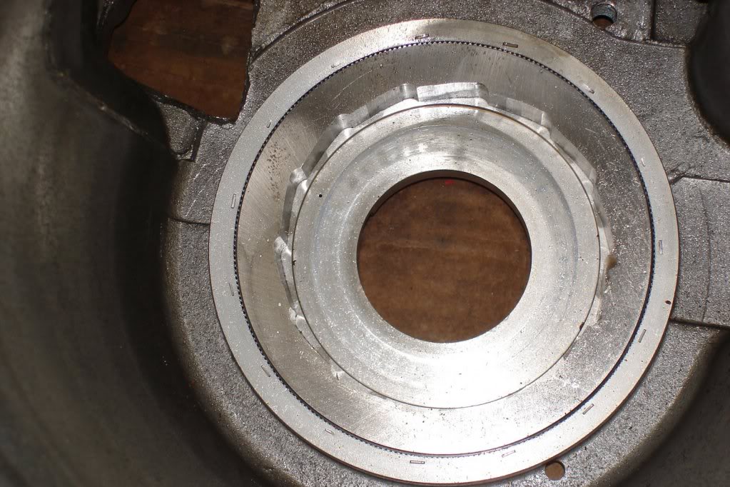
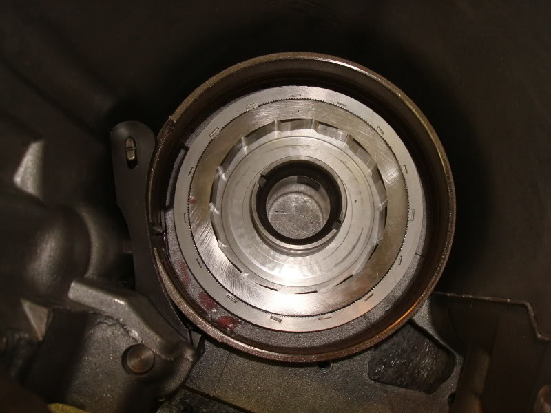
One way clutch race...leave this in the case. It's not really meant to be removed.
Now we need to remove the rear band adjusting lever, reaction lever, and pin. But in order to remove these, the O/D extension housing must be removed. Remove the main case to extension housing bolts. If I remember correctly, theres 7 of them. Set the O/D aside and we'll address that later. When this is removed, you will also notice the O/D piston and the selectable size O/D thrust plate. These need removed to get to the bolts holding the O/D piston retainer onto the main case. Once the extension housing is removed from the main case, then we are able to slide the rear band pin rearward and remove the reaction lever and adjusting lever.
Rear band pin sliding out rearward and out of the adjusting lever and reaction lever.

Remove the adjusting lever, reaction lever, strut, rear band, and rear band link from the case and set the aside together for cleaning and inspection.
Rear band pin, reaction lever, and adjusting lever removed.
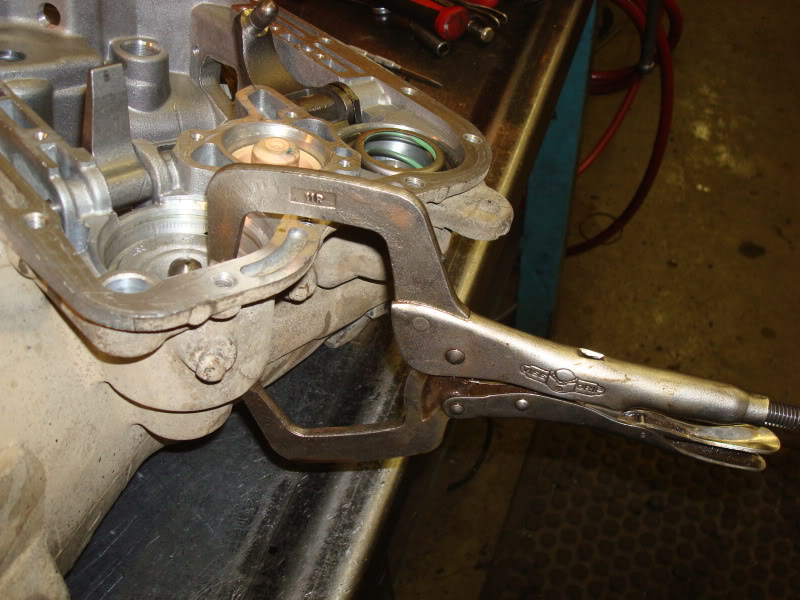
Using a c-clamp tool or c-clamp vice grips, compress the front servo rod guide enough to allow the snap ring to be removed. It doesn't need compressed much, only about 1/8". Use care when removing the snap ring as you do not want to scratch the servo bore. Remove one end of the snap ring, then work it around until it comes out.
Clamped and snap ring removed.
Remove the tools and remove the front servo and spring from the bore.
Using the same method, remove the rear servo snap ring, servo, and servo spring from the bore.
Both servo's and accumulator removed.
You should be completely disassembled now as far as the main case goes. Inventory EVERYTHING and clean it as well. Anything with a seal or o-ring, leave it in place for now so you can match it up with new ones from the kit when it's time to re-install. Next we'll move onto O/D teardown. I'm not covering the disassembly of the front and rear clutch assemblies because it's pretty basic to disassemble these. I will however talk about re-assembling them later on.
O yeah, can't forget to remove the O/D piston retainer from the case. There are 6 fasteners holding it on. Remove these and remove the retainer from the case carefully taking care not to scrape or gall it. It's soft aluminum.
Piston retainer bolts location.
Now we're ready to move onto the O/D housing.
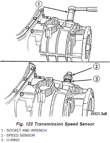
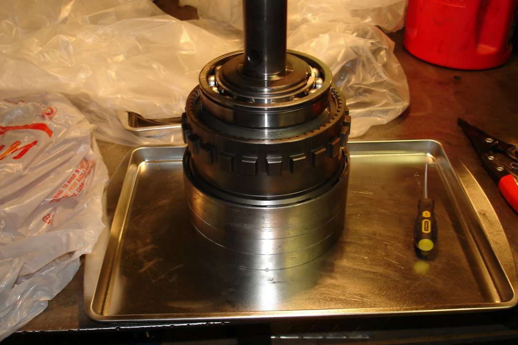
First thing I did was set the O/D upright vertically on two 4x4's straddling the output shaft. Remove the transmission speed sensor and o-ring from the extension housing using a 1" deep well socket. For whatever reason, at the moment I can't find a picture of the speed sensor in my archive. Here's the FSM drawing.
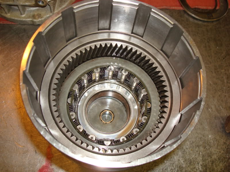
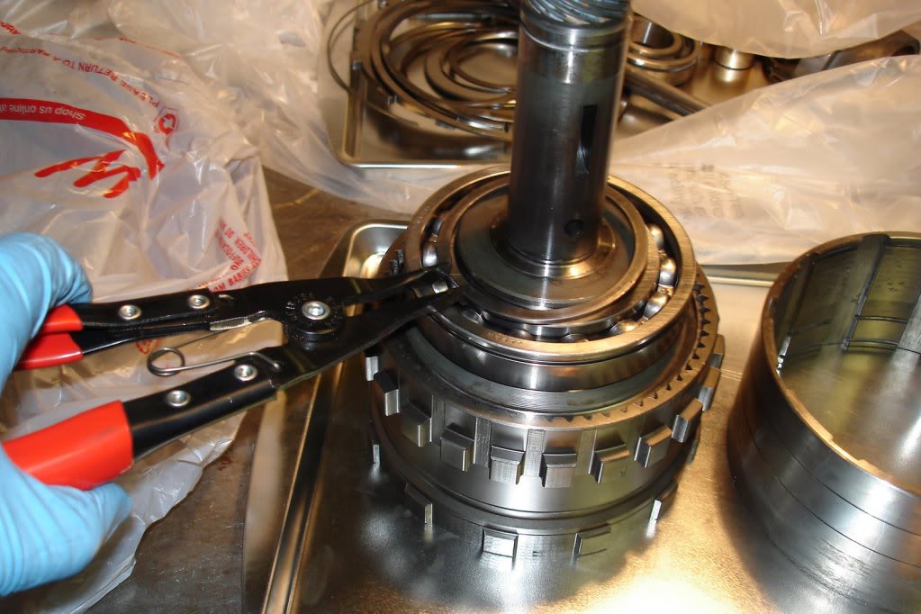
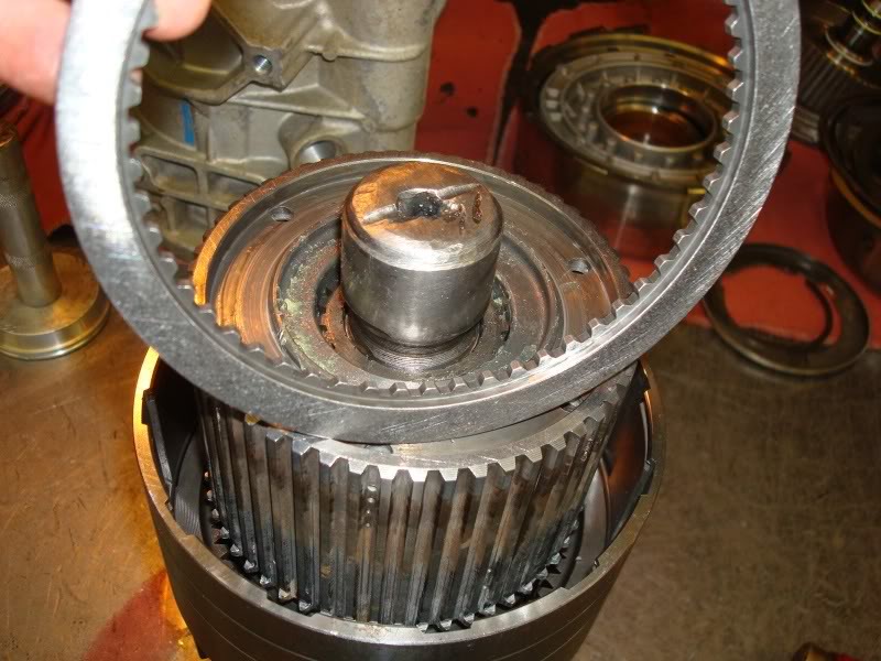
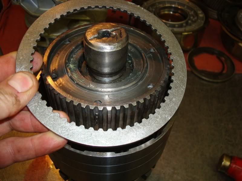
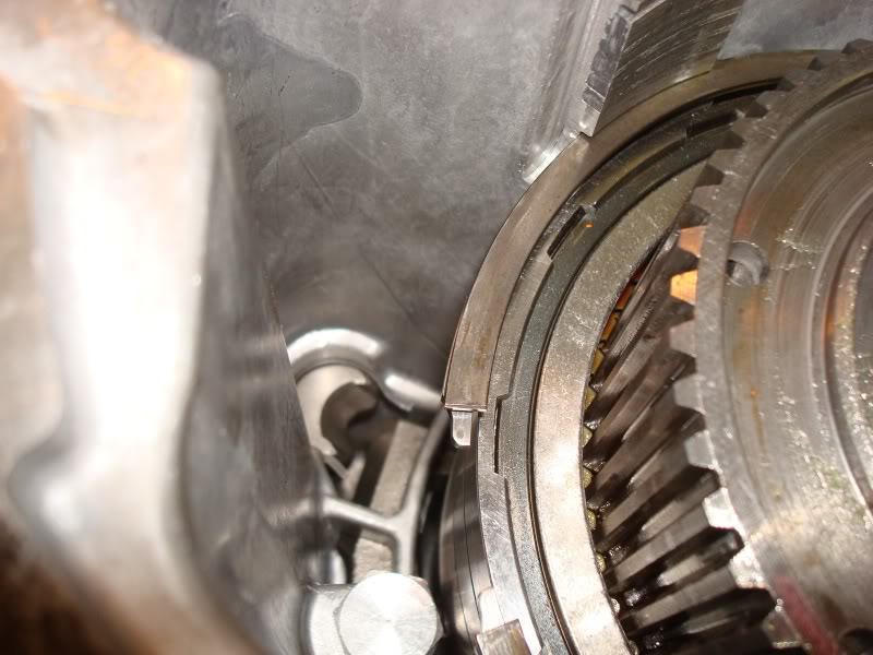
Looking down into the O/D housing, remove the round style snap ring.
Now remove the top pressure plate.
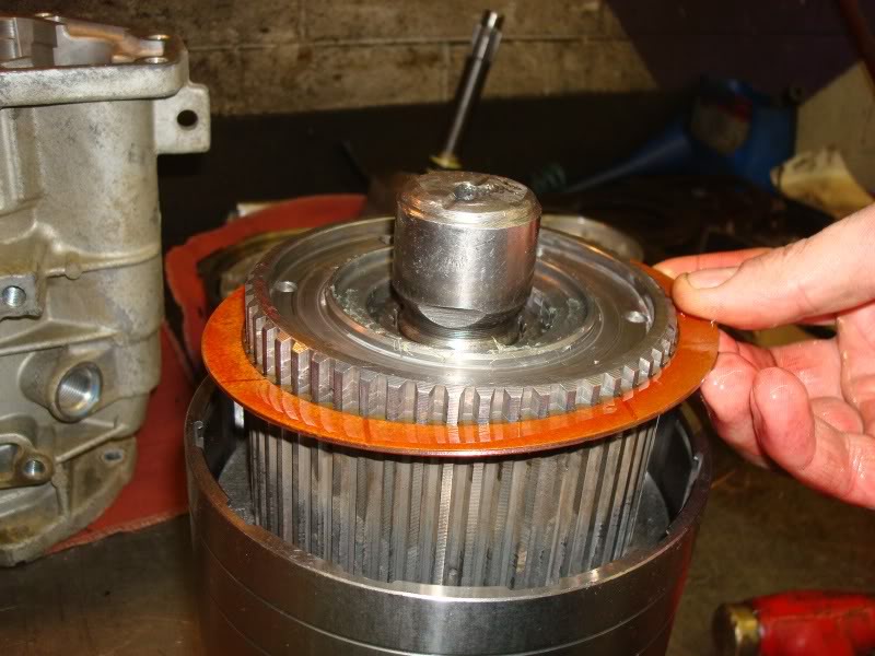
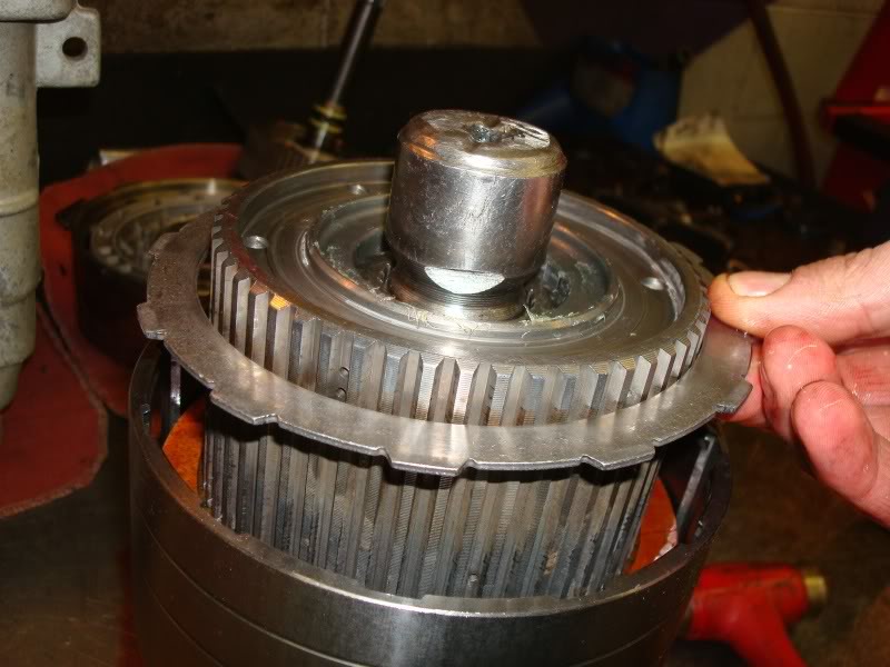
Next remove the first friction.
Keep removing all the frictions and steels and remove the bottom reaction plate. Set these aside and label them O/D clutch pack.
O/D clutch removed.
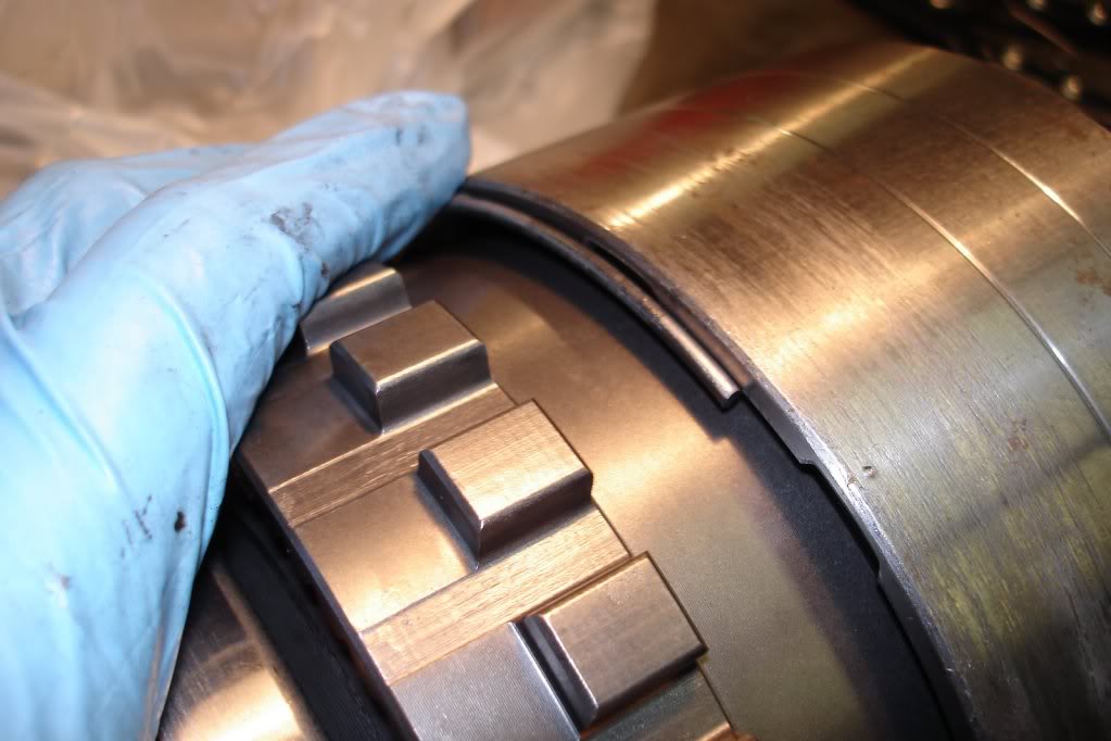
You can also remove the flat wavy style snap ring, and the flat style snap ring from the housing just above the O/D direct clutch pack.
Flat wavy snap ring.

Flat snap ring.

Next, loosen and remove the access cover plate for the O/D bearing locating snap ring. These are Torx heads as well. T-25 I think.
Cover plate and gasket removed.
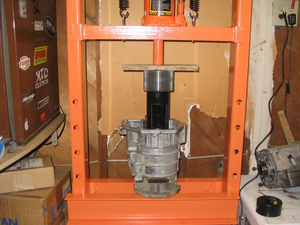
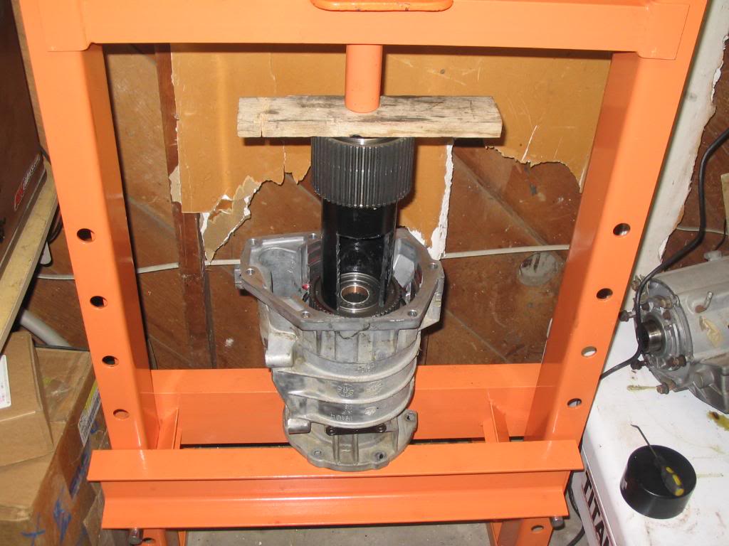
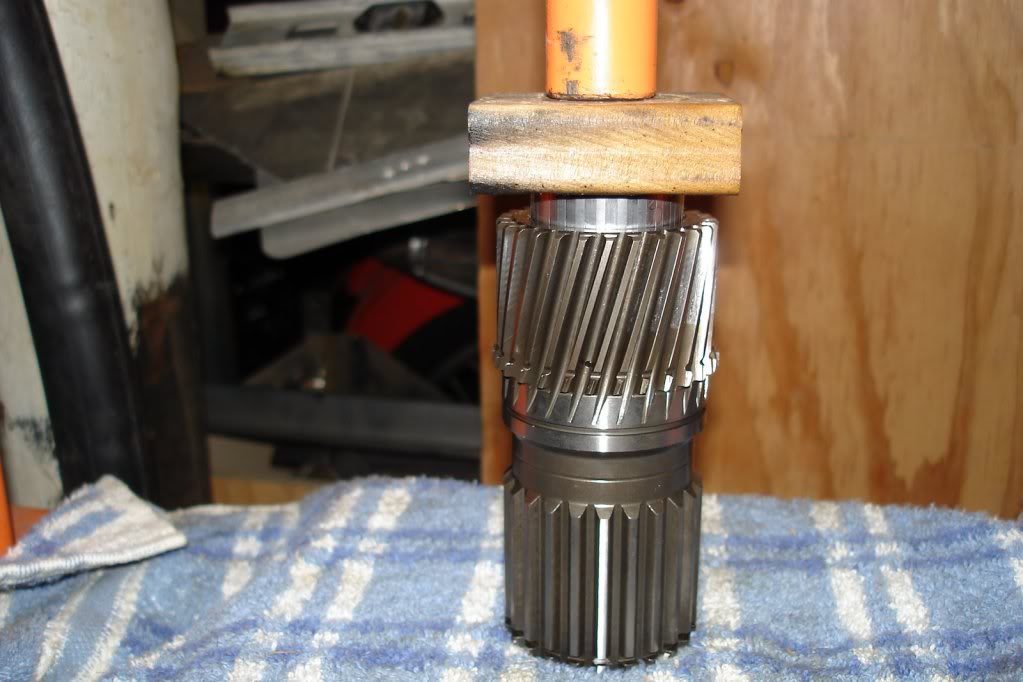
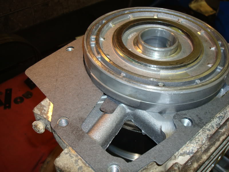
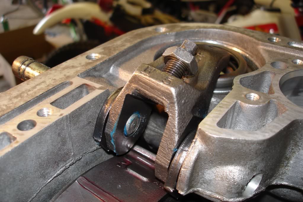
On to the infamous 830 lb. spring. I do not recommend doing this part without a press. Apparently there's a special tool that can be purchased to press against the O/D hub. I fashioned a tool from 3" ABS pipe since I work for a plumbing supply warehouse. Used the dremel to notch the front and rear of the pipe to allow access to the snap rings when the hub is compressed. Here's my setup. Worked flawlessly. The reason why you see the hub on top of the ABS pipe is because it's the old one. This picture was taken after I assembled my O/D unit with new parts and had to disassemble it because my tolerances weren't adding up.
Compress the spring making sure everything is seated nice and firm so nothing can snap under the pressure and slice into you.
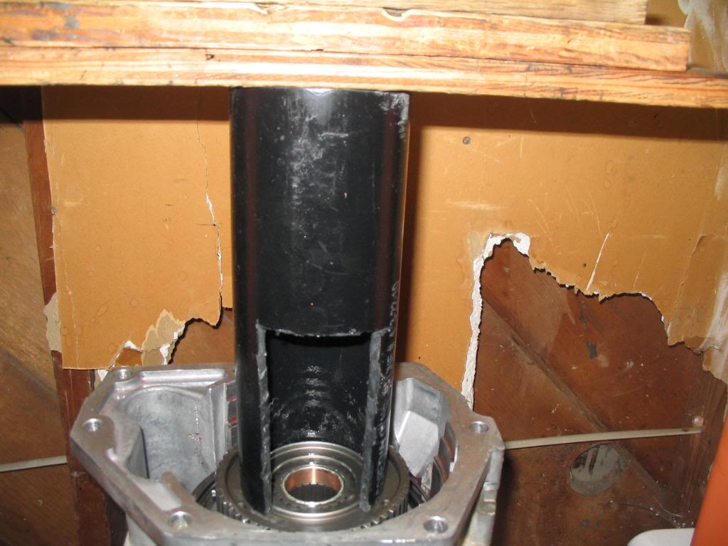
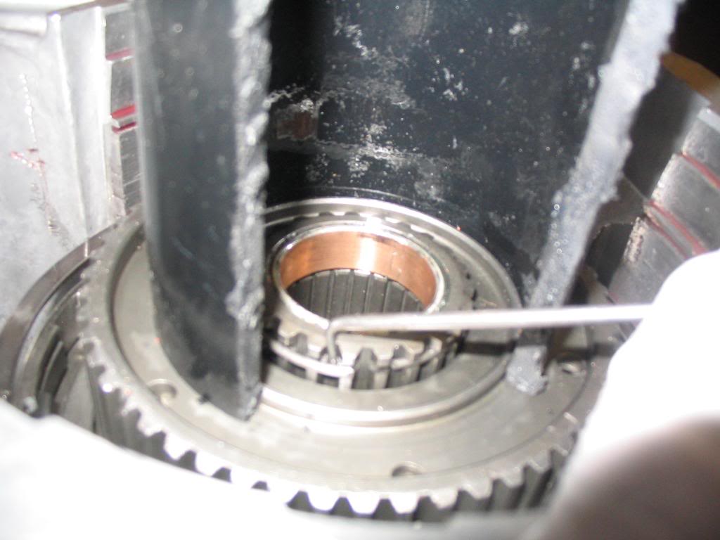
Only compress it far enough to access the center snap ring around the circumference of the sun gear shaft.

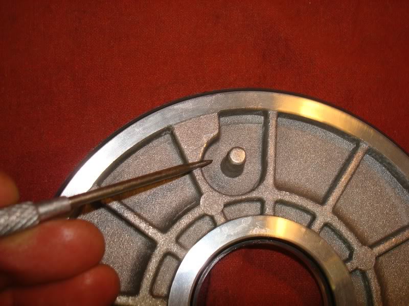
Using a small 90� pick, remove the round snap ring from the sun gear shaft.
With that said, constructive criticism is welcome. But please don't dog on me for the way I do things. I must admit, picture taking wasn't what was really on my mind during disassembly, so I'll try to piece together some pictures from the service manual and other websites online to fill the gap. Digital photos that aren't mine were borrowed from joels garage and jeepforum.com. I just was in a hurry to see what grenaded inside. After you have the tranny down get a nice sized work area cleaned and prepped. There are lots of parts to these units. I used small reusable tupperware dishes with lids and marked them with painters tape and a marker with the corresponding "Fig. #" drawing from the factory service manual during teardown. A digital camera is also worth its weight in gold as a picture is worth a thousand words when its time to reassemble. This is going to be a process writing this up, so please bear with me as I work 60-70 hours a week. I got my parts mostly from www.wittrans.com. Here we go...
Here the transmission is pulled and ready to be disassembled.
Now is a good time to clean the exterior as best as you can to prevent dirt getting in places you don't want. It also allows you to inspect the housing and external components closely.
Stand the transmission up on end with the bell housing facing up. Use 4x4's under the bottom straddling the output shaft. It takes two hands so I don't have a picture of this process. You need to measure the endplay on the input shaft by grabbing it with vice grips and checking vertical movement of the shaft. Record this measurement for assembly reference.
Next you need to remove the throttle and shift levers from the valve body manual shaft and throttle lever shaft on the outside of the case. Basically the external removable linkage.
Linkage removed.
Remove the oil pan and gasket. Pan and gasket removed. The filter is already removed in this picture. It's held in place by 2 Torx-25 fasteners and these are longer than the other valve body fasteners so keep them seperate.
Here's a picture of the filter location. This is a new filter and a picture from re-assembly. But the picture serves its purpose.
Remove the park/neutral position switch and seal. I found a 1" deep socket on my 1/2" drive ratchet works nicely.
Next remove the hex head bolts attaching the valve body to the transmission case. Take note of location and length for assembly reference. There are 10.
Now it's time to remove the valve body from the case. Take care not to damage the case connector that is attached to the valve body that protrudes outside the top/side of the case. It might take a very light tap or two with a rubber mallet to get it jarred loose. The parking rod will also still be attached to the valve body and is removed together. It should pull directly out of the housing. If you have trouble removing it, try turning the output shaft (the rear shaft) slightly to get the pawl to release it. Set the valve body and parking rod aside. You can also remove the accumulator piston and spring in this picture as well. I left all seals in place until it came time for reassembly to make sure I could compare old with new to make sure I had the right seals in the correct spots.
I'm going to stop here tonight. It's getting late for a work night. But I'll be back tomorrow. I'd like to keep this writeup fairly uncluttered, so please, keep the comments to a minimum until I'm finished. Sorry, I'm really not trying to sound like a jerk. Thanks guys.
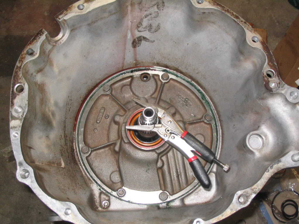
Next you'll want to remove the oil seal for the pump. Use a suitable pry tool. I used a hand hook tool. It's the same seal you see above in the picture with the vice grips on the input shaft and oil pump reaction shaft.
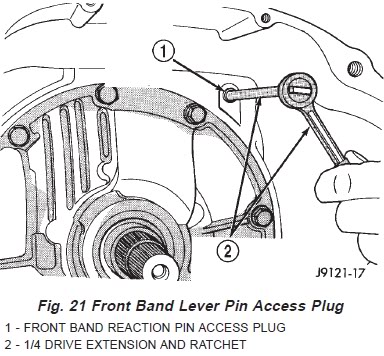
Now remove the band lever pin access cover which is basically a plug in the bell housing. A 1/4" drive extension works nicely removing this. It's in the lower left corner of this picture. Again, an install picture but it works.
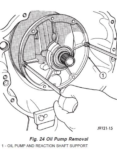
Now it's time to remove the oil pump. The picture above shows two guide pins placed through the oil pump and threaded into the transmission housing. These two particular holes are threaded on the pump housing as well, the threads are just larger. I used 2 6" pieces of 3/8" all thread installed into the threads on the pump housing. Then I put 1 3/8" washer on each piece of all thread with a nut. I used a small 30" piece of that double loop chain thats zinc plated or whatever...the cheap chain you can cut with a good pair of dikes. A couple pulls on the chain with the claw of a hammer and it popped right out. Before you remove the pump though, tighten the front band adjusting screw all the way down. The manual says to do this so you don't accidentally damage the clutches or oil pump. It's the adjuster in this picture that is a Torx-40. Loosen the adjusters locking nut, then tighten the adjuster pin all the way to the right, tightening it.
Now you can remove the pump bolts...I think theres 7. Then use the method described above to pull the pump. Behind the pump, theres a gasket. Remove that too noting its orientation for assembly.
Now back the adjuster for the front band all the way off to its loosest position. Again its the Torx-40 with the locking nut. Then remove the front band strut and anchor.
Adjuster.
Now squeeze the tabs on the front band together and wiggle it out through the front of the bell housing. The tabs prevent you from being able to just remove it easily. You will have to rotate the band around the clutch drum to remove one tab at a time.
Next you'll grab the input shaft with one hand and the front and rear clutch assemblies with your other hand and work them out of the housing as an assembly. There will be two small washers sitting between the intermediate shaft and input shaft when you remove the clutches. One sits in the input shaft and has 3 ears and only fits in the recess of the input shaft one way. The other is the thrust plate washer and it sits on the nipple of the intermediate shaft. Make note of their position and set them in a dish or baggie.
Both thrust washers removed.
Front/Rear clutches and input shaft removed.
Thrust plate location.
3 eared thrust washer location.
Next we'll remove the front band reaction pin and lever. A pencil magnet works good to withdraw the pin from the housing allowing the lever to be removed as well.
Front band lever pin location.
Now remove the intermediate shaft and planetary geartrain as an assembly.
Planetary geartrain and intermediate shaft location.
Now loosen the rear band locknut and loosen the adjuster pin 3-4 turns.
Rear band adjuster locknut and pin location.
Rear band adjuster loosened.
Now remove the snap ring and thrust washer from the center of the low/reverse drum and slide it forward off the O/D piston retainer hub and out of the rear band.
Snap ring location.
Rear drum seated on the hub.
Removing the rear drum from the O/D piston retainer hub.
Notice the over running on way clutch assembly in the bottom of the case. This can be removed very gently so the springs and bearings don't spriong everywhere. The race is pressed into the case and should not be removed.
Over running one way clutch assembly seated in the race.
Removing the over running clutch assembly carefully.
One way clutch race...leave this in the case. It's not really meant to be removed.
Now we need to remove the rear band adjusting lever, reaction lever, and pin. But in order to remove these, the O/D extension housing must be removed. Remove the main case to extension housing bolts. If I remember correctly, theres 7 of them. Set the O/D aside and we'll address that later. When this is removed, you will also notice the O/D piston and the selectable size O/D thrust plate. These need removed to get to the bolts holding the O/D piston retainer onto the main case. Once the extension housing is removed from the main case, then we are able to slide the rear band pin rearward and remove the reaction lever and adjusting lever.
Rear band pin sliding out rearward and out of the adjusting lever and reaction lever.
Remove the adjusting lever, reaction lever, strut, rear band, and rear band link from the case and set the aside together for cleaning and inspection.
Rear band pin, reaction lever, and adjusting lever removed.
Using a c-clamp tool or c-clamp vice grips, compress the front servo rod guide enough to allow the snap ring to be removed. It doesn't need compressed much, only about 1/8". Use care when removing the snap ring as you do not want to scratch the servo bore. Remove one end of the snap ring, then work it around until it comes out.
Clamped and snap ring removed.
Remove the tools and remove the front servo and spring from the bore.
Using the same method, remove the rear servo snap ring, servo, and servo spring from the bore.
Both servo's and accumulator removed.
You should be completely disassembled now as far as the main case goes. Inventory EVERYTHING and clean it as well. Anything with a seal or o-ring, leave it in place for now so you can match it up with new ones from the kit when it's time to re-install. Next we'll move onto O/D teardown. I'm not covering the disassembly of the front and rear clutch assemblies because it's pretty basic to disassemble these. I will however talk about re-assembling them later on.
O yeah, can't forget to remove the O/D piston retainer from the case. There are 6 fasteners holding it on. Remove these and remove the retainer from the case carefully taking care not to scrape or gall it. It's soft aluminum.
Piston retainer bolts location.
Now we're ready to move onto the O/D housing.
First thing I did was set the O/D upright vertically on two 4x4's straddling the output shaft. Remove the transmission speed sensor and o-ring from the extension housing using a 1" deep well socket. For whatever reason, at the moment I can't find a picture of the speed sensor in my archive. Here's the FSM drawing.
Looking down into the O/D housing, remove the round style snap ring.
Now remove the top pressure plate.
Next remove the first friction.
Keep removing all the frictions and steels and remove the bottom reaction plate. Set these aside and label them O/D clutch pack.
O/D clutch removed.
You can also remove the flat wavy style snap ring, and the flat style snap ring from the housing just above the O/D direct clutch pack.
Flat wavy snap ring.
Flat snap ring.
Next, loosen and remove the access cover plate for the O/D bearing locating snap ring. These are Torx heads as well. T-25 I think.
Cover plate and gasket removed.
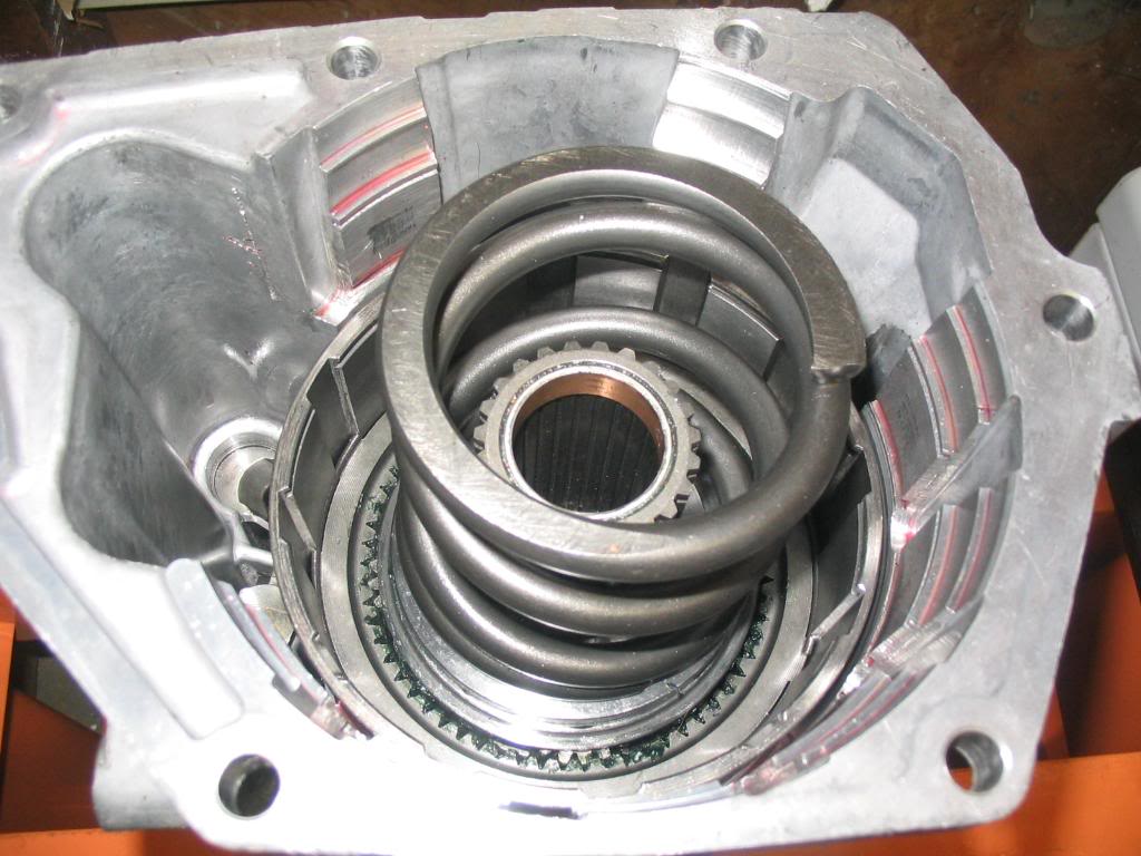
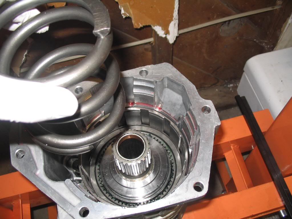
On to the infamous 830 lb. spring. I do not recommend doing this part without a press. Apparently there's a special tool that can be purchased to press against the O/D hub. I fashioned a tool from 3" ABS pipe since I work for a plumbing supply warehouse. Used the dremel to notch the front and rear of the pipe to allow access to the snap rings when the hub is compressed. Here's my setup. Worked flawlessly. The reason why you see the hub on top of the ABS pipe is because it's the old one. This picture was taken after I assembled my O/D unit with new parts and had to disassemble it because my tolerances weren't adding up.
Compress the spring making sure everything is seated nice and firm so nothing can snap under the pressure and slice into you.
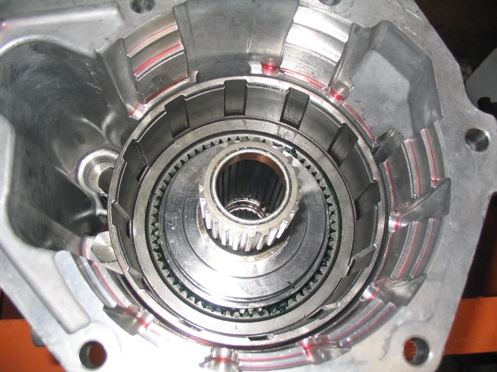
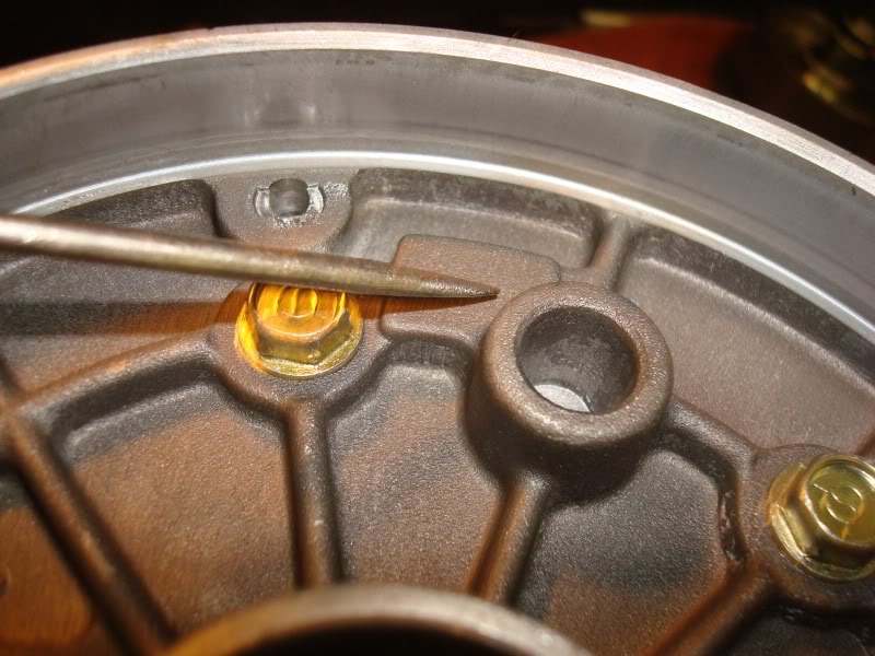
Only compress it far enough to access the center snap ring around the circumference of the sun gear shaft.
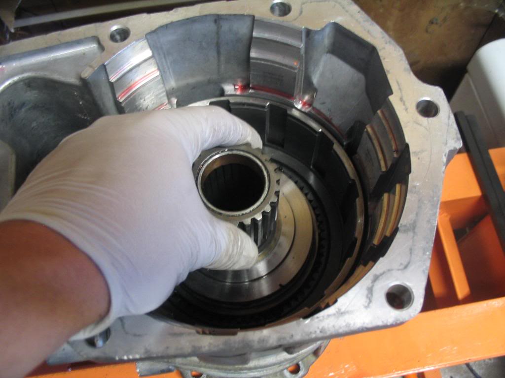
Using a small 90� pick, remove the round snap ring from the sun gear shaft.
Last edited by rocky_mtn_ram; 09-23-2011 at 08:14 PM. Reason: Typo.
#3
09-23-2011, 08:09 PM
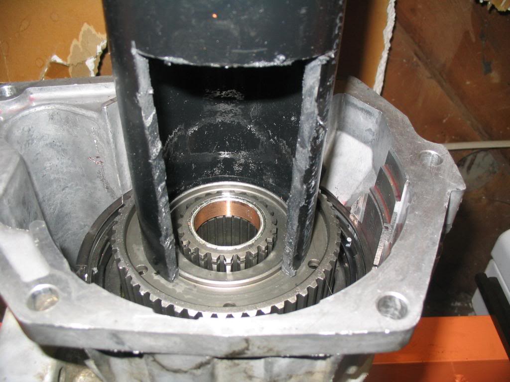
Snap ring removed.
Remove the O/D direct clutch pack snap ring. If it's still there. These things are notorious for snapping. Even if it looks good, replace it. It's cheap insurance at $3.75 or $4.00. This snap ring was the reason for my rebuild. Found about 7 different pieces of it in 7 different areas of the transmission.
Now relieve the pressure on the press and the 830 lb. spring. Now you can remove the O/D direct clutch pack from the housing revealing the large spring and thrust plate it sits on, and planetary assembly.
Remove the spring.
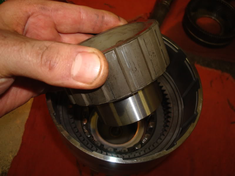
Spring removed. This is the thrust plate/spring seat/bearing race. Its held in place on the sun gear shaft by a snap ring so it can be removed and replaced if needed. If your not replacing it though, leave it on the shaft. The snap ring kicked my butt for some reason, but mine needed replaced. Also, if you have the old style without the oil grooves, I'm pretty sure there's an upgrade available.
Remove the shaft and race. There's a bearing thats either going to be stuck to the bottom of the race, or sitting on the planetary just below. Make note of the orientation of the shoulders on the bearing for assembly reference.
O/D planet to hub bearing stuck to the bottom of the bearing race. Note the inner shoulders of the bearing were facing down, or towards the read of the transmission.
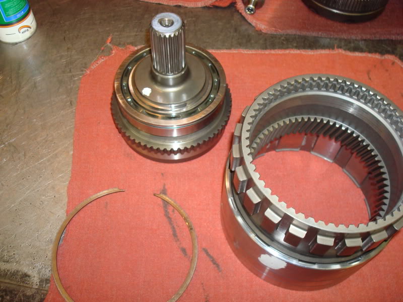
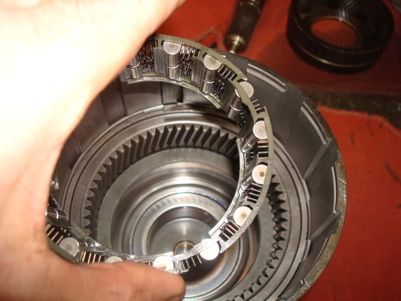
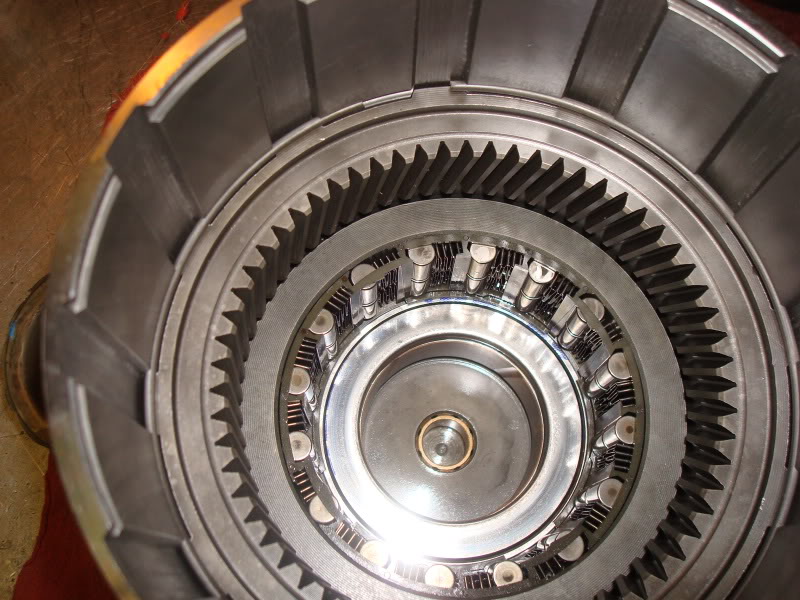
O/D planet assembly. Remove it either using your fingers if your able to, or a pair of snap rings pliers which works pretty darn trick.
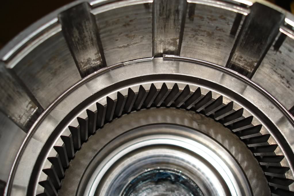
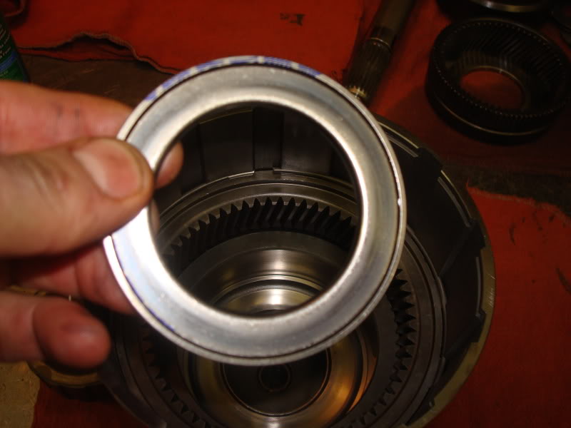
Now all that remains is the output shaft assembly, the O/D sprag and race (one way clutch), and the O/D direct clutch drum.
Remove the sprag and sprag hub using snap ring pliers. Again be careful not to lose any of the springs or rollers. Both sprags should be replaced if in your budget. Roughly $20.00 each.
Remove this bearing. The output shaft to sprag hub bearing. Note the orientation of the shoulders on the bearing for installation.
Stand the housing on 2 4x4's straddling the output shaft. Spread this snap ring open while pushing up on the output shaft. The snap ring sits in a groove on the body of the output shaft bearing. Remove the output shaft, direct clutch drum, ring gear, and output shaft bearing as an assembly.

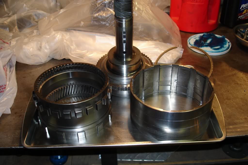
Output shaft assembly. On the bottom is the O/D direct clutch drum. Just above that is the O/D ring gear. The output shaft itself. And the output shaft bearing. There are 3 snap rings holding all this assembly together.
Output shaft assembly.
Set the output shaft up on end with the direct clutch drum facing down. Remove the snap ring from the bearing on top. Then remove the bearing.
Index the direct clutch drum with the ring gear and the ring gear to the output shaft using a paint marker or center punch for assembly balance.
Remove the snap ring securing the output shaft to the ring gear. The output shaft should come loose and can be set aside for cleaning and inspection.
Remove the snap ring on the front side of the ring gear. It is inside the direct clutch drum. Once removed, the ring gear and direct clutch drum can be separated and set aside.
Everything disassembled.
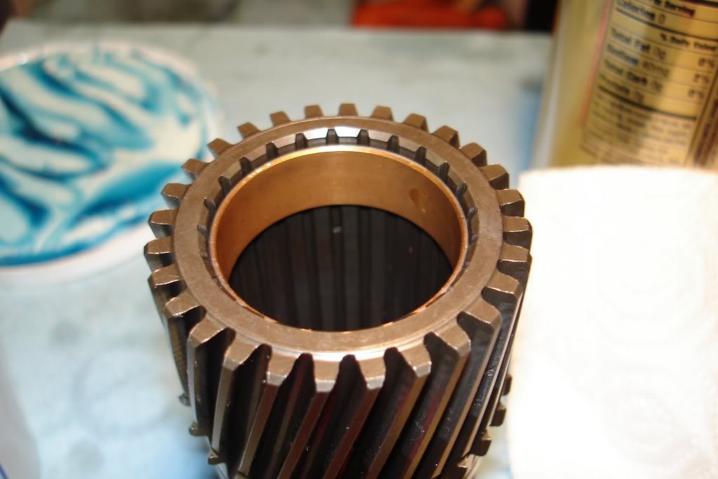
Clean and inventory everything. Next I knocked out all the brass bushings and pressed the replacements in. $150.00 for the press...already paid for itself in my opinion. Start with the output shaft bushing. You shouldn't have needed to order this bushing separate if you ordered the Sure Cure as its part of the kit. The bushing in the center of the shaft (the smallest one) is the one that comes with the Sure Cure. This ones pressed in and lubed with transjel along with the larger diameter bushing. Side note, my old bushing was in two pieces when I disassembled mine. Also, you can remove the parking rod pawl mechanism from the housing and clean and reinstall if you like. I didn't.
Install all the rest of your bushings that you intend on replacing. If you bought the WIT bushing kit, just knock one out at a time and match with the new bushing in the bag and reinstall.
Here's a pic of the sun gear bushings being pressed in.
Now it's just a matter of reassembling everything. I rebuilt the O/D first, then moved to the main case, then attached the two and did the valve body last.
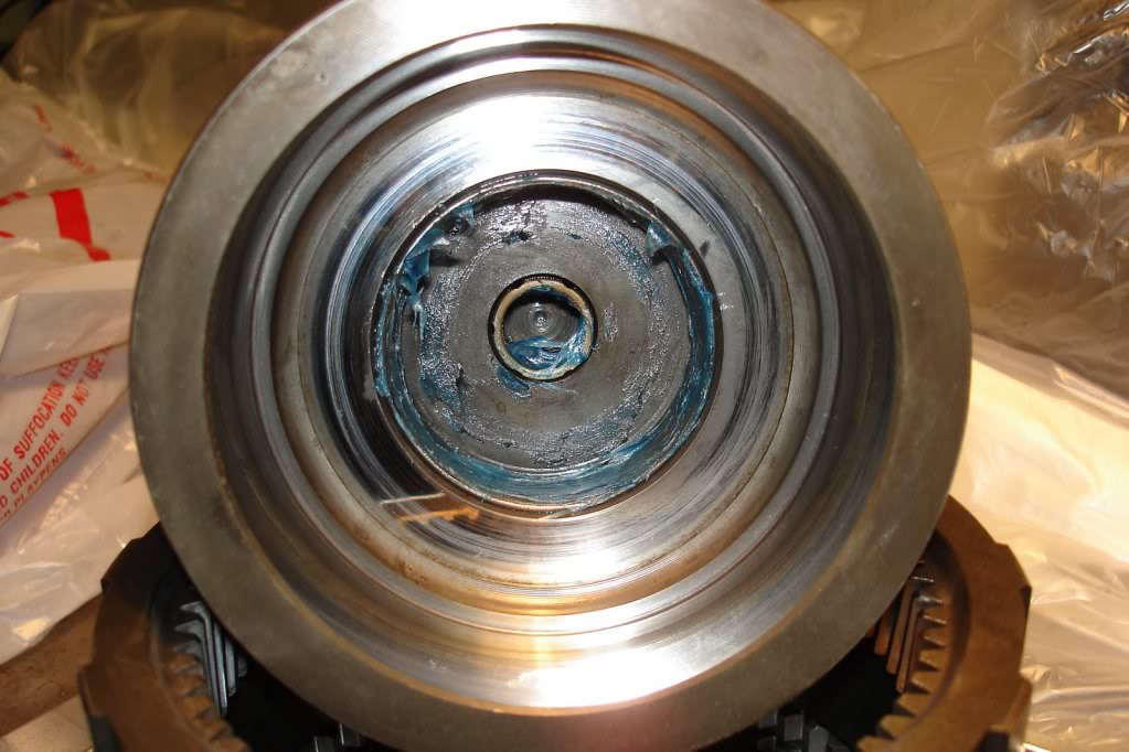
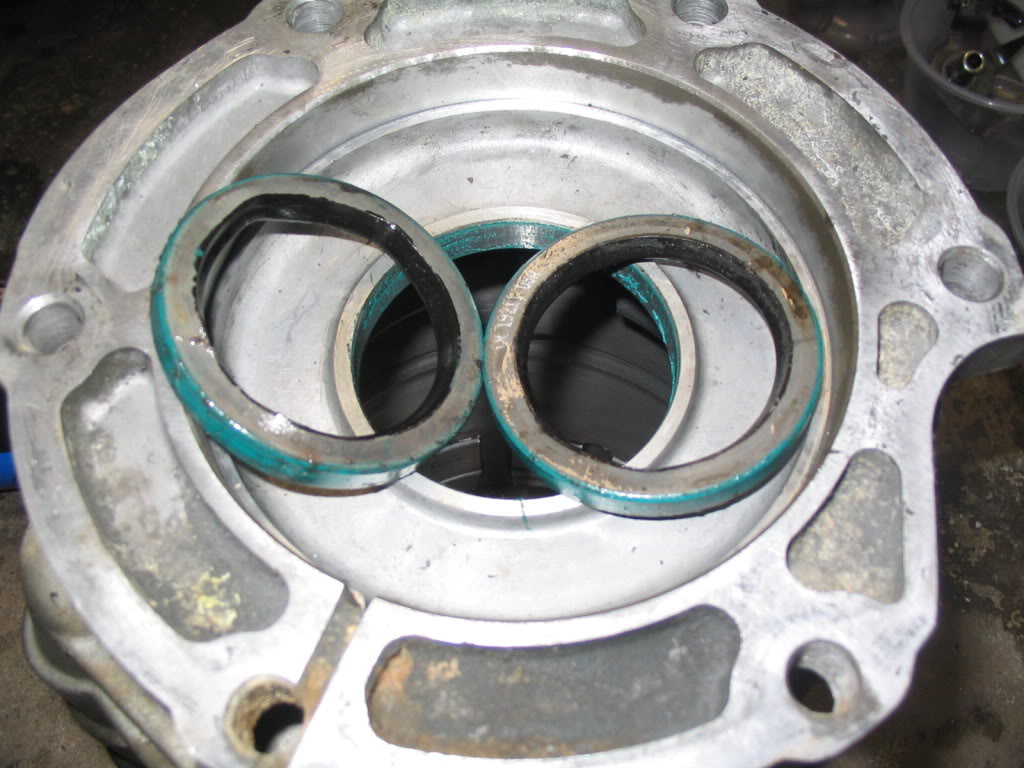
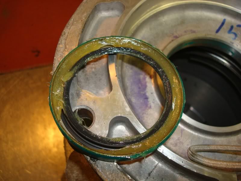
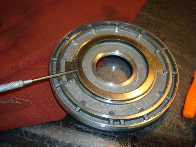
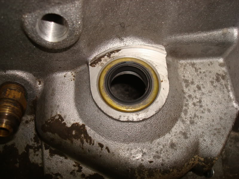
Remove the old output shaft oil seal. I used a corresponding size socket and a hammer to knock mine out. There were actually two seals installed back to back. I guess sometimes people do this on rebuilds to ensure sealing of the output shaft inside and out. Heres a picture of the old seals I removed.
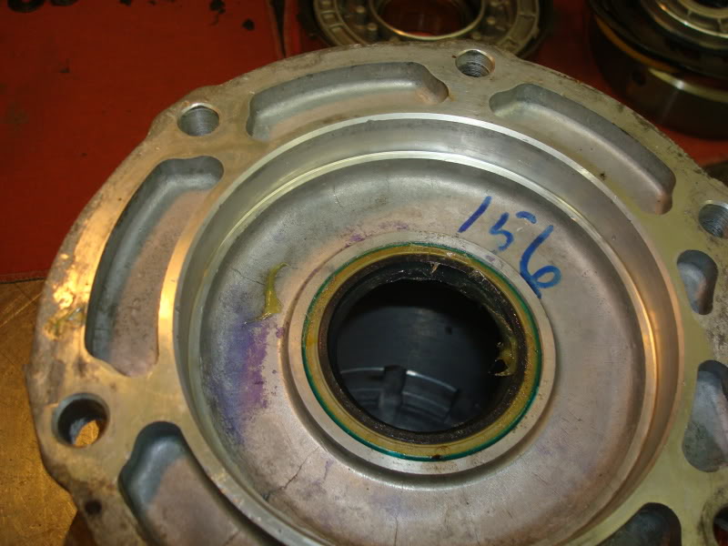
Install the output shaft oil seal making sure to lubricate the seal mating surface with transjel. Lube the seal itself liberally and pack some inside the seal lip on the back to keep the spring inside the seal in place.
Seal installed.
In the main case, reinstall the servos and accumulator. Use the new seals/rings that came with your rebuild kit or shift kit. Lube the servo bores with ATF. In these pictures, they show the plastic style accumulator. I upgraded mine to a aluminum one. Not really sure what this helps, but aluminum is always stronger than plastic, and MonteC recommended this upgrade. So I upgraded.
Rear servo and acuumulator installed.
Installing front servo.

Air check the front servo.
Air check the rear servo.
Reassemble the output shaft, bearing, ring gear, and O/D direct drum and install the retaining snap rings. Make sure your index marks are aligned correctly.
Flip the output shaft assembly over and install the thrust washer. Make sure to place this bearing facing the correct direction or it will disintegrate and your tolerances will be wrong. The inner shoulders goes down, or toward the back of the transmission. The side your looking at goes up, or towards the front of the transmission. Soak it in some ATF for a few seconds.
Install the O/D sprag and note theres a lip on the inner diameter of the cage on the bottom side in this picture. This should be installed seated towards the bottom. This will also destroy itself if installed incorrectly. Careful not to jar or move any of the springs or rollers. This can also be lubed with some ATF.
Sprag installed.
Install the inner race for the sprag. Lube the outter diameter surface with transjel. You might have to rotate the race just right to get the grooves to line up with all the rollers and sink into place. This can be easier to use snap ring pliers to install it so you can hold it from the inside bore.
Race installed. Note its fully seated and flush with the roller cage. If installed correctly, it will only turn one direction. If incorrect, it will freewheel both ways.
Lube the sprag assembly once more with some ATF.
Next, seat the planetary into position aligning the gears with the ones on the ring gear. You can lube the gears in the planetary with transjel before installation.
Install the sun gear thrust bearing to the bottom of the plate making sure the shoulders are correctly positioned. The inner shoulders should be facing the bottom or rear of the transmission. You can use transjel liberally to secure the bearing to the bottom of the plate. You can also lubricate the splines on the gear with transjel.
Install the 830 lb. spring on its seat.
Spring installed.
Now lube the inner splines on the O/D clutch hub and install it over the spring.
If you haven't already, soak your friction pack for the O/D direct clutch and O/D clutch in fresh ATF for at least 20 minutes. Now slide the bottom reaction plate over the hub making sure the skirted end faces down or towards the back of the transmission. The perfectly smooth edge should facing you or up and towards the front of the transmission.
Bottom (face this side down).
Top (this side should face up).
Now it's time to stack the clutch kit up.You can upgrade the 46RE O/D direct clutch pack to have more clutch surface like the 47RE. You can either order a thinner top pressure plate and add another friction, or you could also order a 47RE direct drum as it holds more frictions. Start with adding a friction on top of the bottom reaction plate. Also notice theres a home made alignment tool installed down the center of the hub through the sun gear shaft and down to the center bushing in the output shaft. This one is made from a severed intermediate shaft. You can use your intermediate shaft if you like, this is what I did. It just makes it a little harder when pressing the tension back onto the 830 lb. spring.
First friction.
First steel.
Keep stacking alternating friction then steel until you've got it stacked up almost to the top with enough room to install the pressure plate. Make sure and install the pressure plate with the step facing up towards you or to the front of the transmission. The step is there to accept the snap ring.
Now place the whole assembly back in the press. I had to cut a new piece of ABS pipe that was taller as my piece I originally cut wasn't tall enough to be able to press on the hub with the intermediate shaft installed as an alignment tool. Another advantage of having a severed intermediate shaft because its much shorter and my original piece of pipe I cut would have worked fine. You also might have to lower the legs on the press to accommodate the taller piece of pipe and intermediate shaft. Ok, two things that are very important to watch when your pressing this assembly back together are : a) watch the inner splines on the hub to be sure they are aligning with the sun gear shaft correctly. b) make sure the steps on the outsides of the clutch steels are not caught in a bind as you press. As you press everything together, you will be able to wiggle the clutch pack to get the steels and frictions to fall into place. Once you have them all down in the drum, put the retaining snap ring in.
Now install the center snap ring on the sun gear shaft.
Release the pressure on the press. The sun gear shaft should sit nice and flush with the top of the clutch hub. Maybe recessed the slightest. If it sits above the hub, something in your stackup is installed incorrectly.
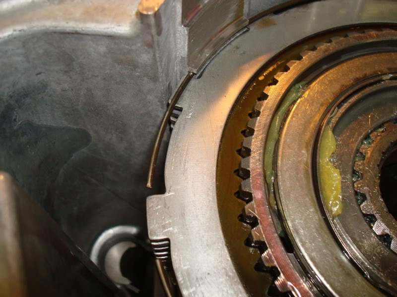
Take the assembly off the press and get your case ready by supporting it by 2 4x4's on the ground or bench. The output shaft oil seal facing down. Slide the O/D and output assembly down into the housing using care not to damage the output shaft oil seal. Try and center the big output shaft bearing on the snap ring so when you spread it open, it falls into place easily. This is what the snap ring and bearing should look like when the snap ring is installed in the groove on the bearing properly. The output shaft and whole rotating assembly should spin nice and freely. Sometimes the bearing and assembly will fall past the snap ring preventing it from engaging, in this case just push up from the bottom of the output shaft. You should hear it snap into place.
Reinstall the access cover using the new gasket from your rebuild kit.

Now from the top, install the flat style snap ring in the groove just above the O/D direct drum.
Now installed the flat waved style snap ring.
Now get the O/D clutch frictions ready to install. The common 46RE has a 4 friction setup in this pack. You can upgrade this easily to hold another friction. All you do is substitute the top thick pressure plate with two more steels and a friction. Giving you 25% more friction surface.
Standard 46RE setup.
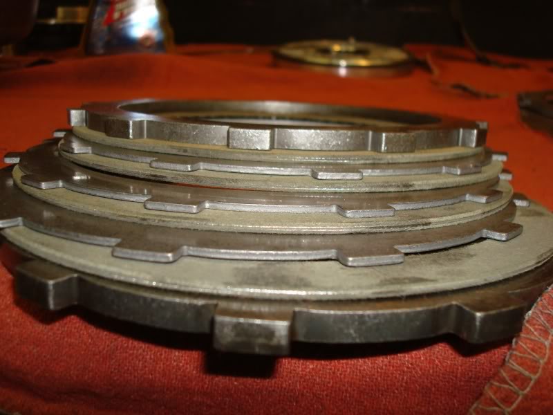
Upgraded 5 friction setup.
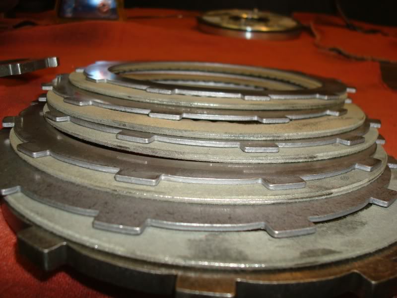
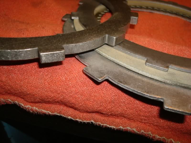
You substitute this thick pressure plate on the left, with 1 friction and two steels on the right, eliminating the pressure plate.
Install the bottom pressure plate first.
First friction.
First steel.
Keep stacking, alternating friction, steel and so forth until its stacked up.
Install the retaining round style snap ring.
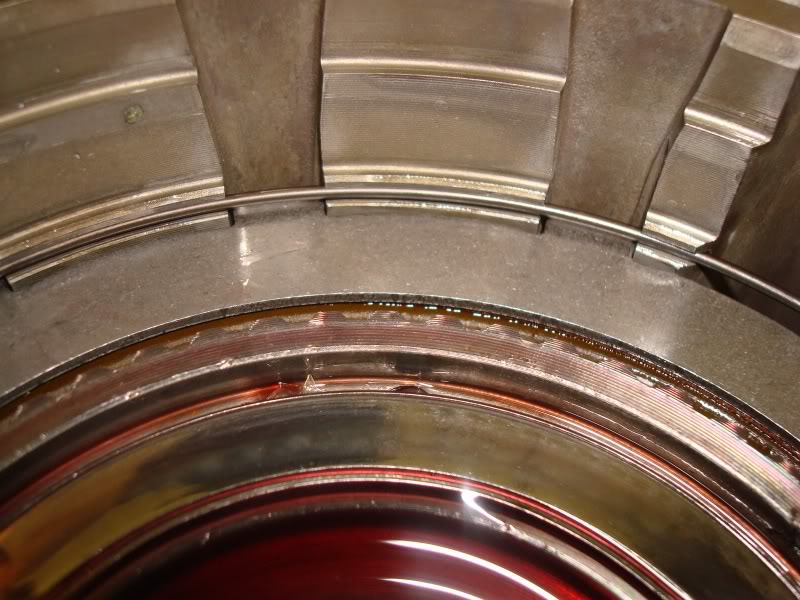
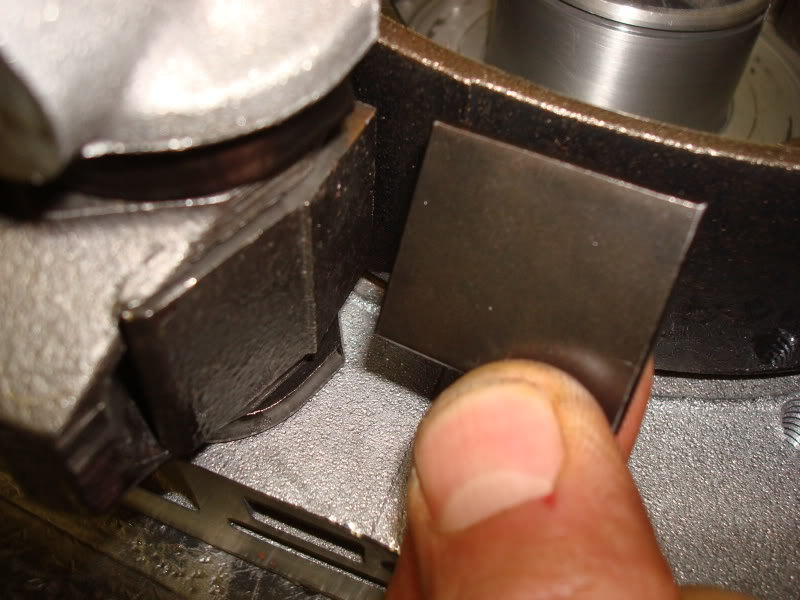
Now we take a mesurement for the O/D thrust plate selectable washer. This washer being sized correctly is crucial for reverse and 3-4 shift. If its the wrong size, you could lose one or the other or both. I set two machined bars across the face of the housing and used those to measure from. The service manuals scale is based on using a .5000" (1/2") bar. Mine was .3950" so I had to do a little math to get my reading. Basically just added .105" to my reading. I struggled with getting this measurement to come out correctly. I took my O/D apart about 5 times I think until I got the measurement to add up correctly. Basically what threw me off was the steels in my old setup were thicker. So with the new thinner steels installed to allow for more frictions, I didn't have enough frictions and steels installed. Once I figured out the exact problem, it was fixed quickly. My measurement came out to 1.7415". So adding my .105" to that gave me 1.8465". This means I need the .198"-.200" shim. Make sure and take this measurement with the thrust bearing itself NOT in place. Place your straight edge across the housing allowing the bottom of the caliper to extend down the housing on to the top of the clutch hub. Take this measurement 4 times 90�'s apart. Average the 4 measurements to get your final measurement. This pic was from joels garage and he's working on a unit with the governor tubes in the extension housing in the upper right corner.
Now you can glue the bearing to the face of the hub using transjel. Make sure the bearing is facing the correct direction according to its shoulders.
Remove the O/D direct clutch pack snap ring. If it's still there. These things are notorious for snapping. Even if it looks good, replace it. It's cheap insurance at $3.75 or $4.00. This snap ring was the reason for my rebuild. Found about 7 different pieces of it in 7 different areas of the transmission.
Now relieve the pressure on the press and the 830 lb. spring. Now you can remove the O/D direct clutch pack from the housing revealing the large spring and thrust plate it sits on, and planetary assembly.
Remove the spring.
Spring removed. This is the thrust plate/spring seat/bearing race. Its held in place on the sun gear shaft by a snap ring so it can be removed and replaced if needed. If your not replacing it though, leave it on the shaft. The snap ring kicked my butt for some reason, but mine needed replaced. Also, if you have the old style without the oil grooves, I'm pretty sure there's an upgrade available.
Remove the shaft and race. There's a bearing thats either going to be stuck to the bottom of the race, or sitting on the planetary just below. Make note of the orientation of the shoulders on the bearing for assembly reference.
O/D planet to hub bearing stuck to the bottom of the bearing race. Note the inner shoulders of the bearing were facing down, or towards the read of the transmission.
O/D planet assembly. Remove it either using your fingers if your able to, or a pair of snap rings pliers which works pretty darn trick.
Now all that remains is the output shaft assembly, the O/D sprag and race (one way clutch), and the O/D direct clutch drum.
Remove the sprag and sprag hub using snap ring pliers. Again be careful not to lose any of the springs or rollers. Both sprags should be replaced if in your budget. Roughly $20.00 each.
Remove this bearing. The output shaft to sprag hub bearing. Note the orientation of the shoulders on the bearing for installation.
Stand the housing on 2 4x4's straddling the output shaft. Spread this snap ring open while pushing up on the output shaft. The snap ring sits in a groove on the body of the output shaft bearing. Remove the output shaft, direct clutch drum, ring gear, and output shaft bearing as an assembly.
Output shaft assembly. On the bottom is the O/D direct clutch drum. Just above that is the O/D ring gear. The output shaft itself. And the output shaft bearing. There are 3 snap rings holding all this assembly together.
Output shaft assembly.
Set the output shaft up on end with the direct clutch drum facing down. Remove the snap ring from the bearing on top. Then remove the bearing.
Index the direct clutch drum with the ring gear and the ring gear to the output shaft using a paint marker or center punch for assembly balance.
Remove the snap ring securing the output shaft to the ring gear. The output shaft should come loose and can be set aside for cleaning and inspection.
Remove the snap ring on the front side of the ring gear. It is inside the direct clutch drum. Once removed, the ring gear and direct clutch drum can be separated and set aside.
Everything disassembled.
Clean and inventory everything. Next I knocked out all the brass bushings and pressed the replacements in. $150.00 for the press...already paid for itself in my opinion. Start with the output shaft bushing. You shouldn't have needed to order this bushing separate if you ordered the Sure Cure as its part of the kit. The bushing in the center of the shaft (the smallest one) is the one that comes with the Sure Cure. This ones pressed in and lubed with transjel along with the larger diameter bushing. Side note, my old bushing was in two pieces when I disassembled mine. Also, you can remove the parking rod pawl mechanism from the housing and clean and reinstall if you like. I didn't.
Install all the rest of your bushings that you intend on replacing. If you bought the WIT bushing kit, just knock one out at a time and match with the new bushing in the bag and reinstall.
Here's a pic of the sun gear bushings being pressed in.
Now it's just a matter of reassembling everything. I rebuilt the O/D first, then moved to the main case, then attached the two and did the valve body last.
Remove the old output shaft oil seal. I used a corresponding size socket and a hammer to knock mine out. There were actually two seals installed back to back. I guess sometimes people do this on rebuilds to ensure sealing of the output shaft inside and out. Heres a picture of the old seals I removed.
Install the output shaft oil seal making sure to lubricate the seal mating surface with transjel. Lube the seal itself liberally and pack some inside the seal lip on the back to keep the spring inside the seal in place.
Seal installed.
In the main case, reinstall the servos and accumulator. Use the new seals/rings that came with your rebuild kit or shift kit. Lube the servo bores with ATF. In these pictures, they show the plastic style accumulator. I upgraded mine to a aluminum one. Not really sure what this helps, but aluminum is always stronger than plastic, and MonteC recommended this upgrade. So I upgraded.
Rear servo and acuumulator installed.
Installing front servo.
Air check the front servo.
Air check the rear servo.
Reassemble the output shaft, bearing, ring gear, and O/D direct drum and install the retaining snap rings. Make sure your index marks are aligned correctly.
Flip the output shaft assembly over and install the thrust washer. Make sure to place this bearing facing the correct direction or it will disintegrate and your tolerances will be wrong. The inner shoulders goes down, or toward the back of the transmission. The side your looking at goes up, or towards the front of the transmission. Soak it in some ATF for a few seconds.
Install the O/D sprag and note theres a lip on the inner diameter of the cage on the bottom side in this picture. This should be installed seated towards the bottom. This will also destroy itself if installed incorrectly. Careful not to jar or move any of the springs or rollers. This can also be lubed with some ATF.
Sprag installed.
Install the inner race for the sprag. Lube the outter diameter surface with transjel. You might have to rotate the race just right to get the grooves to line up with all the rollers and sink into place. This can be easier to use snap ring pliers to install it so you can hold it from the inside bore.
Race installed. Note its fully seated and flush with the roller cage. If installed correctly, it will only turn one direction. If incorrect, it will freewheel both ways.
Lube the sprag assembly once more with some ATF.
Next, seat the planetary into position aligning the gears with the ones on the ring gear. You can lube the gears in the planetary with transjel before installation.
Install the sun gear thrust bearing to the bottom of the plate making sure the shoulders are correctly positioned. The inner shoulders should be facing the bottom or rear of the transmission. You can use transjel liberally to secure the bearing to the bottom of the plate. You can also lubricate the splines on the gear with transjel.
Install the 830 lb. spring on its seat.
Spring installed.
Now lube the inner splines on the O/D clutch hub and install it over the spring.
If you haven't already, soak your friction pack for the O/D direct clutch and O/D clutch in fresh ATF for at least 20 minutes. Now slide the bottom reaction plate over the hub making sure the skirted end faces down or towards the back of the transmission. The perfectly smooth edge should facing you or up and towards the front of the transmission.
Bottom (face this side down).
Top (this side should face up).
Now it's time to stack the clutch kit up.You can upgrade the 46RE O/D direct clutch pack to have more clutch surface like the 47RE. You can either order a thinner top pressure plate and add another friction, or you could also order a 47RE direct drum as it holds more frictions. Start with adding a friction on top of the bottom reaction plate. Also notice theres a home made alignment tool installed down the center of the hub through the sun gear shaft and down to the center bushing in the output shaft. This one is made from a severed intermediate shaft. You can use your intermediate shaft if you like, this is what I did. It just makes it a little harder when pressing the tension back onto the 830 lb. spring.
First friction.
First steel.
Keep stacking alternating friction then steel until you've got it stacked up almost to the top with enough room to install the pressure plate. Make sure and install the pressure plate with the step facing up towards you or to the front of the transmission. The step is there to accept the snap ring.
Now place the whole assembly back in the press. I had to cut a new piece of ABS pipe that was taller as my piece I originally cut wasn't tall enough to be able to press on the hub with the intermediate shaft installed as an alignment tool. Another advantage of having a severed intermediate shaft because its much shorter and my original piece of pipe I cut would have worked fine. You also might have to lower the legs on the press to accommodate the taller piece of pipe and intermediate shaft. Ok, two things that are very important to watch when your pressing this assembly back together are : a) watch the inner splines on the hub to be sure they are aligning with the sun gear shaft correctly. b) make sure the steps on the outsides of the clutch steels are not caught in a bind as you press. As you press everything together, you will be able to wiggle the clutch pack to get the steels and frictions to fall into place. Once you have them all down in the drum, put the retaining snap ring in.
Now install the center snap ring on the sun gear shaft.
Release the pressure on the press. The sun gear shaft should sit nice and flush with the top of the clutch hub. Maybe recessed the slightest. If it sits above the hub, something in your stackup is installed incorrectly.
Take the assembly off the press and get your case ready by supporting it by 2 4x4's on the ground or bench. The output shaft oil seal facing down. Slide the O/D and output assembly down into the housing using care not to damage the output shaft oil seal. Try and center the big output shaft bearing on the snap ring so when you spread it open, it falls into place easily. This is what the snap ring and bearing should look like when the snap ring is installed in the groove on the bearing properly. The output shaft and whole rotating assembly should spin nice and freely. Sometimes the bearing and assembly will fall past the snap ring preventing it from engaging, in this case just push up from the bottom of the output shaft. You should hear it snap into place.
Reinstall the access cover using the new gasket from your rebuild kit.
Now from the top, install the flat style snap ring in the groove just above the O/D direct drum.
Now installed the flat waved style snap ring.
Now get the O/D clutch frictions ready to install. The common 46RE has a 4 friction setup in this pack. You can upgrade this easily to hold another friction. All you do is substitute the top thick pressure plate with two more steels and a friction. Giving you 25% more friction surface.
Standard 46RE setup.
Upgraded 5 friction setup.
You substitute this thick pressure plate on the left, with 1 friction and two steels on the right, eliminating the pressure plate.
Install the bottom pressure plate first.
First friction.
First steel.
Keep stacking, alternating friction, steel and so forth until its stacked up.
Install the retaining round style snap ring.
Now we take a mesurement for the O/D thrust plate selectable washer. This washer being sized correctly is crucial for reverse and 3-4 shift. If its the wrong size, you could lose one or the other or both. I set two machined bars across the face of the housing and used those to measure from. The service manuals scale is based on using a .5000" (1/2") bar. Mine was .3950" so I had to do a little math to get my reading. Basically just added .105" to my reading. I struggled with getting this measurement to come out correctly. I took my O/D apart about 5 times I think until I got the measurement to add up correctly. Basically what threw me off was the steels in my old setup were thicker. So with the new thinner steels installed to allow for more frictions, I didn't have enough frictions and steels installed. Once I figured out the exact problem, it was fixed quickly. My measurement came out to 1.7415". So adding my .105" to that gave me 1.8465". This means I need the .198"-.200" shim. Make sure and take this measurement with the thrust bearing itself NOT in place. Place your straight edge across the housing allowing the bottom of the caliper to extend down the housing on to the top of the clutch hub. Take this measurement 4 times 90�'s apart. Average the 4 measurements to get your final measurement. This pic was from joels garage and he's working on a unit with the governor tubes in the extension housing in the upper right corner.
Now you can glue the bearing to the face of the hub using transjel. Make sure the bearing is facing the correct direction according to its shoulders.
Last edited by rocky_mtn_ram; 09-25-2011 at 01:34 PM.
#4
09-25-2011, 12:19 AM
Install the selectable shim on the O/D piston face using transjel, then install the piston into the O/D piston retainer. If your rebuild kit came with new seals, install them matching up with the old seals as a size reference. There is a seal on the inner and outter diameter of the piston.
Selectable shim glued in place to bottom of piston.
These notches must align when installing the piston into the piston retainer.
Piston male notch.
Piston retainer female notch.
Install the piston retainer and new gasket to the main case. If your new piston retainer is the style that has an extra groove for the oring, install the oring. Bolt it up and torque it down. Be sure if you bought a new one, that if you DO NOT have the governor tubes, use the aluminum plugs that came with the new retainer and press them into the holes to plug them.

Install the O/D piston into the piston retainer after you've installed new seals and lubed everything up. Make sure you align the male and female notches and it seats completely. Installing the lips of the seals without folding them up can be kinda tricky. My Transtec rebuild kit came with the "Lip Wizard" which is just a thin strip of transparent green plastic cut in a circle, about the size of a coffee can lid. Some people say you can use a really thin feeler gauge with the edges sanded smooth. Lubricate the seals and the mating retainer surfaces. Work the inner lip over the inner diameter of the retainer first. Then work the outter diameter seal into place until you've got it seated.
[youtube]NxOQJ4mvz7Y[/youtube]
Piston installed in retainer.
Bolt the O/D to the main case and dont forget the O/D housing to main housing gasket. Before you do this, put the low/reverse band anchor pin in its bore. Install new orings if your rebuild kit came with these.
Lubricate and install the overrunning clutch. Lube the rollers and the race with transjel.

Install the low/reverse band, anchor, pin, and lever. Make sure the band is seated in the anchor fully.
Install the lower part of the lever that pushes on the servo.
Installed.
Lube the piston retainer to help with installing the low/reverse drum. Also lube the inner diameter of the drum as well.
Drum and new washer with snap ring.
Installed.
Install a new shifter seal from the rebuild kit.
Selectable shim glued in place to bottom of piston.
These notches must align when installing the piston into the piston retainer.
Piston male notch.
Piston retainer female notch.
Install the piston retainer and new gasket to the main case. If your new piston retainer is the style that has an extra groove for the oring, install the oring. Bolt it up and torque it down. Be sure if you bought a new one, that if you DO NOT have the governor tubes, use the aluminum plugs that came with the new retainer and press them into the holes to plug them.
Install the O/D piston into the piston retainer after you've installed new seals and lubed everything up. Make sure you align the male and female notches and it seats completely. Installing the lips of the seals without folding them up can be kinda tricky. My Transtec rebuild kit came with the "Lip Wizard" which is just a thin strip of transparent green plastic cut in a circle, about the size of a coffee can lid. Some people say you can use a really thin feeler gauge with the edges sanded smooth. Lubricate the seals and the mating retainer surfaces. Work the inner lip over the inner diameter of the retainer first. Then work the outter diameter seal into place until you've got it seated.
[youtube]NxOQJ4mvz7Y[/youtube]
Piston installed in retainer.
Bolt the O/D to the main case and dont forget the O/D housing to main housing gasket. Before you do this, put the low/reverse band anchor pin in its bore. Install new orings if your rebuild kit came with these.
Lubricate and install the overrunning clutch. Lube the rollers and the race with transjel.
Install the low/reverse band, anchor, pin, and lever. Make sure the band is seated in the anchor fully.
Install the lower part of the lever that pushes on the servo.
Installed.
Lube the piston retainer to help with installing the low/reverse drum. Also lube the inner diameter of the drum as well.
Drum and new washer with snap ring.
Installed.
Install a new shifter seal from the rebuild kit.
Last edited by rocky_mtn_ram; 09-25-2011 at 12:38 AM.
The following users liked this post:
luis.ramos (05-24-2020)
#5
01-30-2012, 09:03 PM
Rebuild videos.
http://s809.photobucket.com/albums/z...ansmission.mp4
http://s809.photobucket.com/albums/z...ssionPart2.mp4
http://s809.photobucket.com/albums/z...ssionPart3.mp4
http://s809.photobucket.com/albums/z...ssionPart4.mp4
http://s809.photobucket.com/albums/z...ssionPart5.mp4
http://s809.photobucket.com/albums/z...ssionPart6.mp4
#7
09-22-2014, 05:37 PM

I bookmarked your thread for my 46re rebuild. I'm almost ready to start on it, but all your pics are gone.
Trending Topics
#8
09-22-2014, 09:27 PM
He hasn't been around for a year..... and from what I am seeing, he has just ran out of bandwidth. Pics are still there, just not showing at the moment. My guess is, that whenever he enters a new cycle, maybe beginning of the month, the pics will be back.
Welcome to DF!
Welcome to DF!