
Offroad/ Fog lights
#1
 12-02-2013, 05:54 PM

Join Date: Oct 2013
Location: BC, Canada
Posts: 139
Likes: 0
Received 0 Likes
on
0 Posts
Ok, so last week, I bought some wiring and mounted some lights that I took off from my old Ford. They're two Baja 100W lights, that came with a 30A relay, hooked them up under the bumper:
put the 2 + wires together, went to the relay(Pin 30)
both of the -/ grounds to a good ground beside my washer fluid reservoir
1 Wire going from the relay with an inline fuse(15A) to the battery from relay(Pin 87)
Then 1 wire from the relay to the switch(which is also grounded(Pin 85)
Then Pin 86 to a clean ground.
So, after that, I went and picked up a 40A relay and wired it as such: (Always hot)
Pin 87&86 to the battery with same 15A inline fuse
Pin 30 to lights
Pin 85 to switch.
Since this didnt work, I tested the voltage, getting 12V from battery, to the relay, but nothing at the switch or wires going to/ from anywhere. A bit new to wiring, as my old Ford came with everything hooked up and working, so from all of this, am I missing something
All of this is using 14 gauge wires, with some splice connectors.
#2
12-02-2013, 06:02 PM

Pins 85 and 86 are your control circuits. Put power to one, the other to ground to turn 'on' the relay. (put a switch on either side of it to actually control the relay.)
Pin 30 is power feed from the battery for the load the relay controls. I *think* pin 87a is powered when the relay control circuit is NOT energized, and pin 87 will have power when it is. Test this theory before finalizing your wiring.
Pin 30 is power feed from the battery for the load the relay controls. I *think* pin 87a is powered when the relay control circuit is NOT energized, and pin 87 will have power when it is. Test this theory before finalizing your wiring.

#4
12-02-2013, 10:25 PM
Join Date: Oct 2013
Location: BC, Canada
Posts: 139
Likes: 0
Received 0 Likes
on
0 Posts
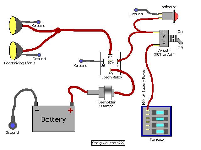
This is the initial diagram I was following, but it didn't work for me.
I have pin 85 to the switch, then on the other terminal of the switch is grounded. I figured it needed to be grounded out, but it doesn't? This is almost giving me a headache lol.
I have pin 85 to the switch, then on the other terminal of the switch is grounded. I figured it needed to be grounded out, but it doesn't? This is almost giving me a headache lol.
#5
12-02-2013, 10:54 PM
the diagram above is correct.
don't ground the switch unless it has a ground terminal. a single pole switch should simply turn on/off the 12volt positive power feed.
in the diagram above the extra pigtail from the switch is powering an indicator light which requires a ground. if you don't have an indicator light, remove that entire little pigtail and its ground.
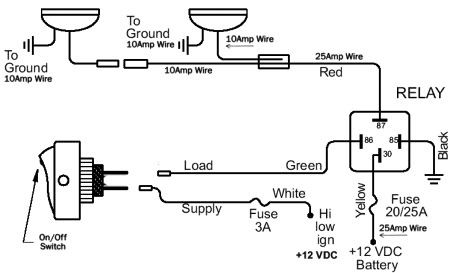
here's a diagram with no indicator light and a non-grounded switch.
don't ground the switch unless it has a ground terminal. a single pole switch should simply turn on/off the 12volt positive power feed.
in the diagram above the extra pigtail from the switch is powering an indicator light which requires a ground. if you don't have an indicator light, remove that entire little pigtail and its ground.
here's a diagram with no indicator light and a non-grounded switch.
#6
12-02-2013, 11:18 PM
Join Date: Oct 2013
Location: BC, Canada
Posts: 139
Likes: 0
Received 0 Likes
on
0 Posts
the diagram above is correct.
don't ground the switch unless it has a ground terminal. a single pole switch should simply turn on/off the 12volt positive power feed.
in the diagram above the extra pigtail from the switch is powering an indicator light which requires a ground. if you don't have an indicator light, remove that entire little pigtail and its ground.
here's a diagram with no indicator light and a non-grounded switch.
Thank you for being very helpful