
Cruise Control Question
#11
 12-18-2011, 10:37 AM


#12
12-18-2011, 01:10 PM
Alright, as promised here's some pictures of everything from the factory service manual.
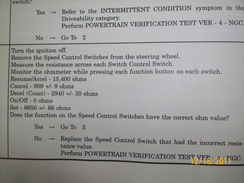
Here you can see the ohm values for each button.
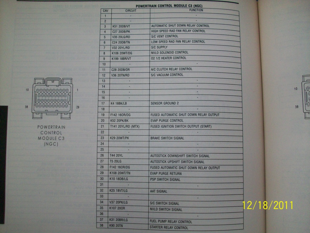
On the NGC PCM (this is what I have on my 03 2.4L sedan) Everything for the cruise is on connector 3. You're looking at pins 5 and 12 which feed ground to the cruise servo to control it. Pin 7 is the power output running through the brake switch to all the relays in the cruise servo. Pin 23 is a common brake sense that takes a ground, runs it through the brake switch and to the PCM when the brake is not depressed, this controls things like cruise, brake shift interlock and ABS. Pin 17 is important as that goes to the cruise switches as the ground feed and is also grounded inside the cabin too. Pin 34 is all your cruise switch outputs, this is where it sends out 5 volts and looks for feedback from the switches. If anyone has the other type PCM in their car, I also have a pinout for that one too.
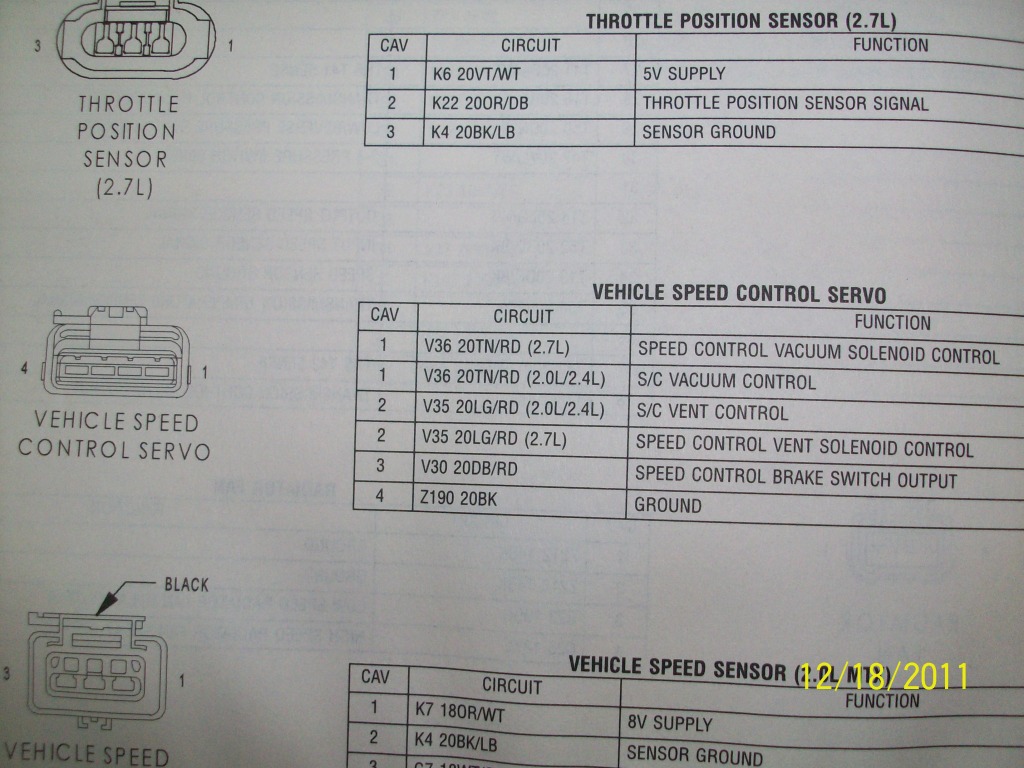
This is the connector that plugs into the speed control servo. Pins 1 and 2 are directly connected to the PCM outputs and get grounded to activate. Pin 3 is the power from the PCM for the relays. Pin 4 is just a ground.

Here is a wiring diagram for how the system works. C3 is connector 3 and -xx after it is the pin number.
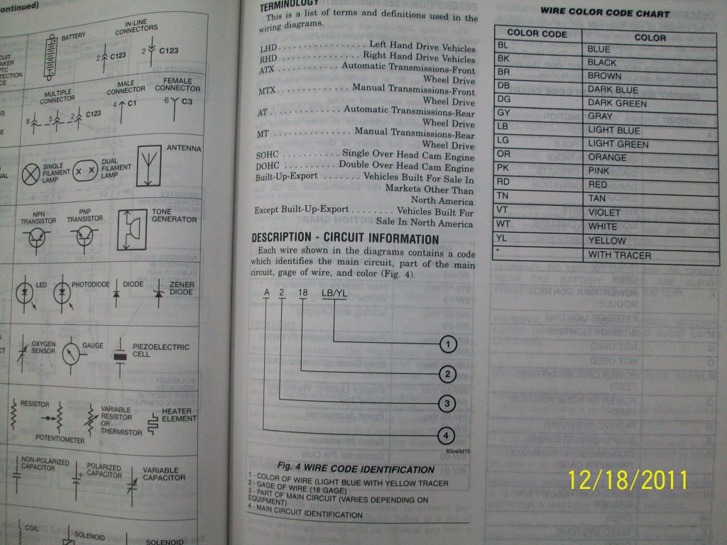
This tells you the wire color codes and wire gage.

Here is another digagram of the system telling you wire colors. Notice ground G103 and G203, these both need to be good for the cruise to work.
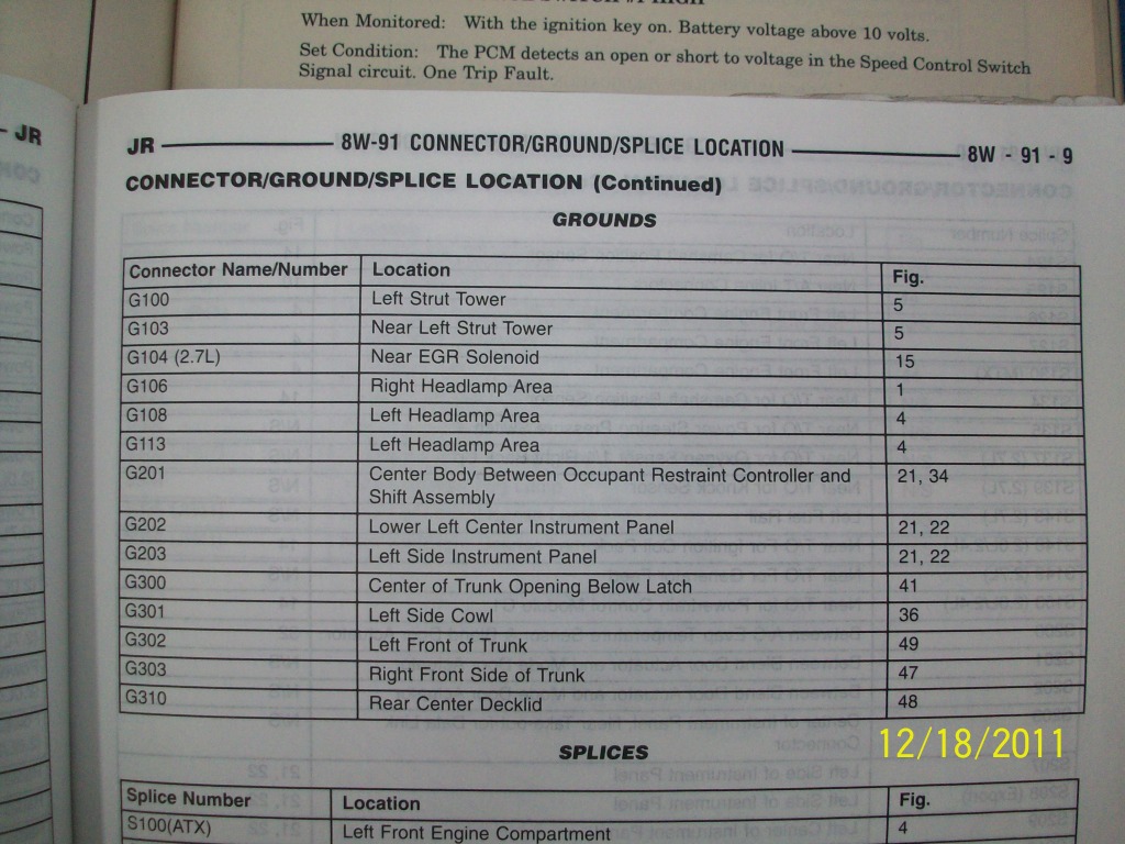
This tells you where the 2 ground locations are.
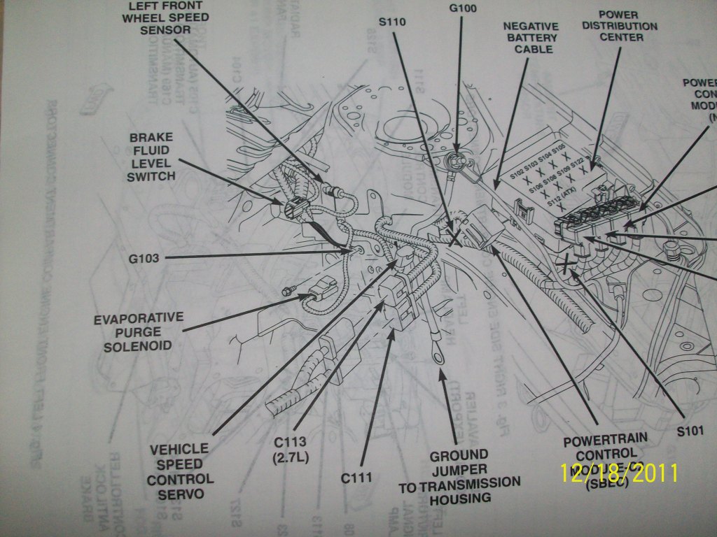
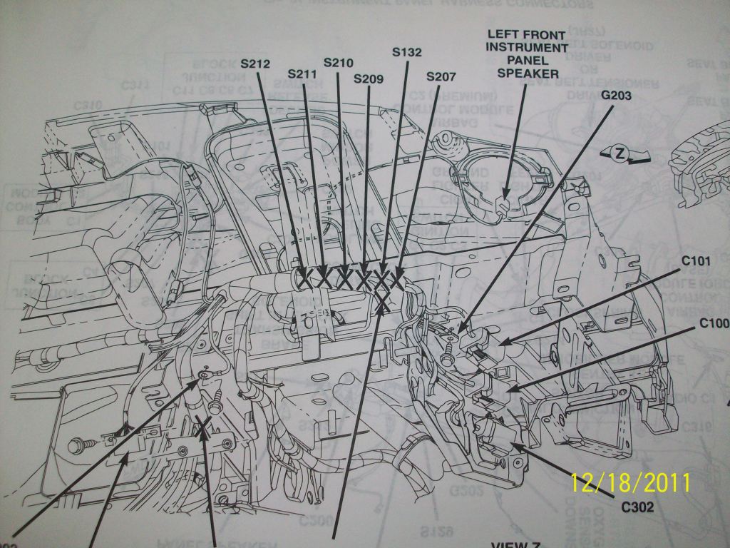
And these pictures show you diagrams of where to locate the grounding points.
Hope this helps anyone in the future to fix problems with their cruise control. If anyone wants a picture of the older PCM pinouts I can add them here too.
Here you can see the ohm values for each button.
On the NGC PCM (this is what I have on my 03 2.4L sedan) Everything for the cruise is on connector 3. You're looking at pins 5 and 12 which feed ground to the cruise servo to control it. Pin 7 is the power output running through the brake switch to all the relays in the cruise servo. Pin 23 is a common brake sense that takes a ground, runs it through the brake switch and to the PCM when the brake is not depressed, this controls things like cruise, brake shift interlock and ABS. Pin 17 is important as that goes to the cruise switches as the ground feed and is also grounded inside the cabin too. Pin 34 is all your cruise switch outputs, this is where it sends out 5 volts and looks for feedback from the switches. If anyone has the other type PCM in their car, I also have a pinout for that one too.
This is the connector that plugs into the speed control servo. Pins 1 and 2 are directly connected to the PCM outputs and get grounded to activate. Pin 3 is the power from the PCM for the relays. Pin 4 is just a ground.
Here is a wiring diagram for how the system works. C3 is connector 3 and -xx after it is the pin number.
This tells you the wire color codes and wire gage.
Here is another digagram of the system telling you wire colors. Notice ground G103 and G203, these both need to be good for the cruise to work.
This tells you where the 2 ground locations are.
And these pictures show you diagrams of where to locate the grounding points.
Hope this helps anyone in the future to fix problems with their cruise control. If anyone wants a picture of the older PCM pinouts I can add them here too.
Last edited by Evon Trizmo; 12-18-2011 at 01:18 PM.
#13
12-19-2011, 07:20 AM

#14
12-23-2011, 09:12 AM

#15
12-23-2011, 10:07 AM
#16
12-23-2011, 11:10 AM
#17
12-23-2011, 11:25 AM
Those are both cruise control modules but neither would work in your car. Technically you could get either to work if you spliced the VSS into the speed pin on the box and added individual switches for each button function. You can only use only 2 of the exsisting buttons on the steering wheel, using the horn ground wire as a ground, see whether the button pins respond to ground or 12v, if it's 12v then run some relays from the grounded steering wheel switches to close a 12v circuit. Then the rest of the buttons have to be mounted on the dash or somewhere else. Then see whether the boxes output ground on the vac and vent pins or 12v, if it's 12v they will have to drive relays to close a ground path to the vac and vent pins of the speed control servo. And finally don't forget to connect your brake pedal switch to the brake pin, first see if grounding it will shut of the cruise, if not put 12v from the brake lamp circuit on it.
That's how you can get those to work, deffinatly not a plug and play system, I'd only do that if I needed a new PCM to get the cruise working, but that's rarely the case. You'd probably be much better off repairing your exsisting system, start by following the wiring digagrams in my picture to check all the wiring and make sure nothing is shorted/open. Usually clocksprings are the weak point there. Then try replacing or cleaning and testing the brake lamp switch, then if that doesn't work clean or replace your cruise control switches on the steering wheel, if that doesn't work replace your cruise servo, if that doesn't work it's your ECU.
That's how you can get those to work, deffinatly not a plug and play system, I'd only do that if I needed a new PCM to get the cruise working, but that's rarely the case. You'd probably be much better off repairing your exsisting system, start by following the wiring digagrams in my picture to check all the wiring and make sure nothing is shorted/open. Usually clocksprings are the weak point there. Then try replacing or cleaning and testing the brake lamp switch, then if that doesn't work clean or replace your cruise control switches on the steering wheel, if that doesn't work replace your cruise servo, if that doesn't work it's your ECU.
Last edited by Evon Trizmo; 12-23-2011 at 11:28 AM.
#18
12-23-2011, 12:01 PM
everything you said makes a lot of sense, as i am planning to do exactly this, rewiring all connections
i think it should work since the new modules are vaccum operated, as is my stratus
please read my post in another thread, transcripted below:
my 1997 stratus has a defective cruise control, it never worked since i bought it 2 years ago
i have followed all testing steps in the chrysler service manual and everything is ok: brake switch, vacuum lines, servo, pcm, steering wheel switches, voltages, no broken wires, no shorts, no loose connections, no obd codes, no nothing, everything is fine
the cruise lamp on the panel lights on when pressing the on switch, but the set switch does not engage it
i replaced the pcm for a new one, but it didn't fix it
well, very frustating to say the least
i recently found on ebay a cruise control module taken from a 2002 stratus
it has a 20-pin connector, but no wiring diagram is available
can anybody tell me if this module would work in my car, after making the proper wirings?
or else, does anybody have a clue of what is happening to my cruise control?
i think you have just answered both questions
#19
12-23-2011, 12:15 PM
Glad I can help, if all else fails and you're out of ideas, replace the cruise servo, very rarely they fail but I have seen a few times solenoids going bad in them and nothing works, inside they use Chrysler's idea of very simplified but very difficult to understand circuit layouts with many failsafes in place. There's 3 solenoids and a diode inside, all controlled by only 2 signal wires. I found units from neons to Durangos are all the same, I'd go ahead and match year rather than vehicle, or something that has a PCM that looks like yours since the PCM checks resistance on the solenoids to make sure everything will work before it sets the speed. My cruise servo failed in my 03 Stratus a few years ago, I replaced one from an 02 Intrepid with the Huntsville NGC like I have and it's been working fine since.
#20
12-23-2011, 12:24 PM
the first thing i did, two years ago, was to replace the servo for a new one and surprise... it didn't work
the service manual has a testing sequence for the servo, and i can guarantee that its pulling the cable with engine vaccum
maybe i am missing something
gonna try installing a separate module and let you know if it works
the service manual has a testing sequence for the servo, and i can guarantee that its pulling the cable with engine vaccum
maybe i am missing something
gonna try installing a separate module and let you know if it works