
My Official Solid Axle Swap Thread (The Project Writeup)
#21
 05-12-2010, 05:35 PM

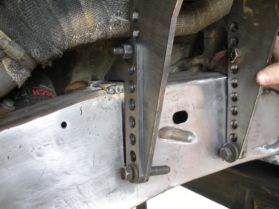
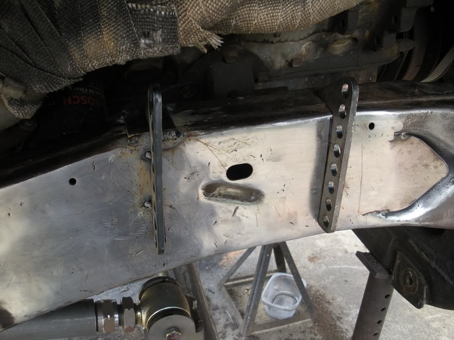
So now that the frame has been "flattened", its finally time to mount the coil spring towers. I started by strapping them to the frame to see how flat and level they would sit...
As you can see, the rear rail is 1/2 low of the front rail. I had two ways to deal with this... put a 1/2 inch spacer on the rear rail, or put a 1/4 inch spacer on the rear rail and cut 1/4 inch off the front rail. As you can see in the below picture, the top of the frame is not flat, so the rail needs to be trimmed anyway, so I decided to cut 1/4 inch off the front rail and put a 1/4 inch spacer on the rear rail.
After trimming...
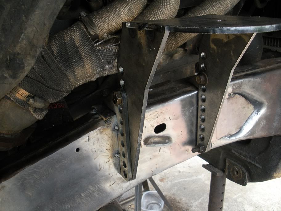
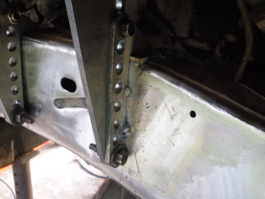
So I did another test fit after getting the spacer in and trimming the rails...

And I was satisfied with the fit, so I tacked it on the frame.
The other side needs to be done the same way, and measured out from some point on the frame thats the same on both sides to make sure they are equal.
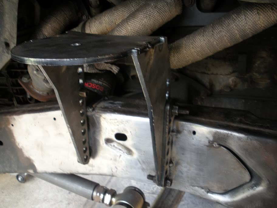
Here is the other side...
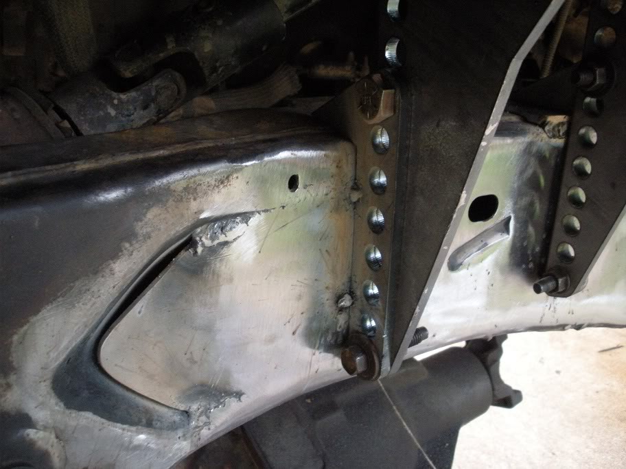
As you can see, these are adjustable coil towers... so once the rails are welded onto the frame, the towers can be mounted at whatever height is needed!
As you can see, the rear rail is 1/2 low of the front rail. I had two ways to deal with this... put a 1/2 inch spacer on the rear rail, or put a 1/4 inch spacer on the rear rail and cut 1/4 inch off the front rail. As you can see in the below picture, the top of the frame is not flat, so the rail needs to be trimmed anyway, so I decided to cut 1/4 inch off the front rail and put a 1/4 inch spacer on the rear rail.
After trimming...
So I did another test fit after getting the spacer in and trimming the rails...
And I was satisfied with the fit, so I tacked it on the frame.
The other side needs to be done the same way, and measured out from some point on the frame thats the same on both sides to make sure they are equal.
Here is the other side...
As you can see, these are adjustable coil towers... so once the rails are welded onto the frame, the towers can be mounted at whatever height is needed!
Last edited by 95_318SLT; 05-12-2010 at 08:00 PM.
#22
05-24-2010, 10:56 AM
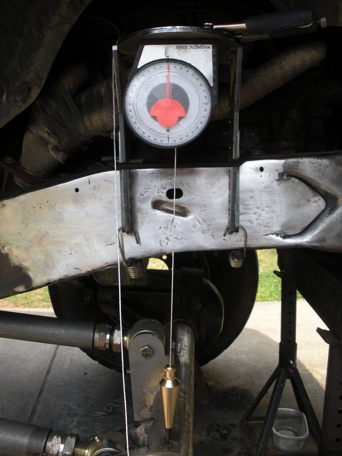
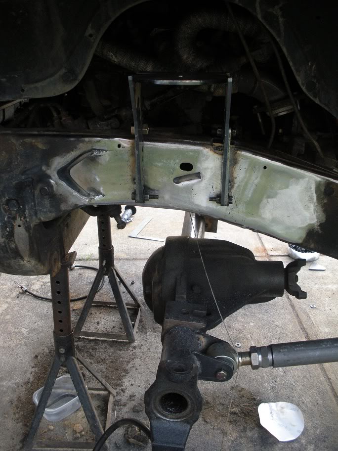
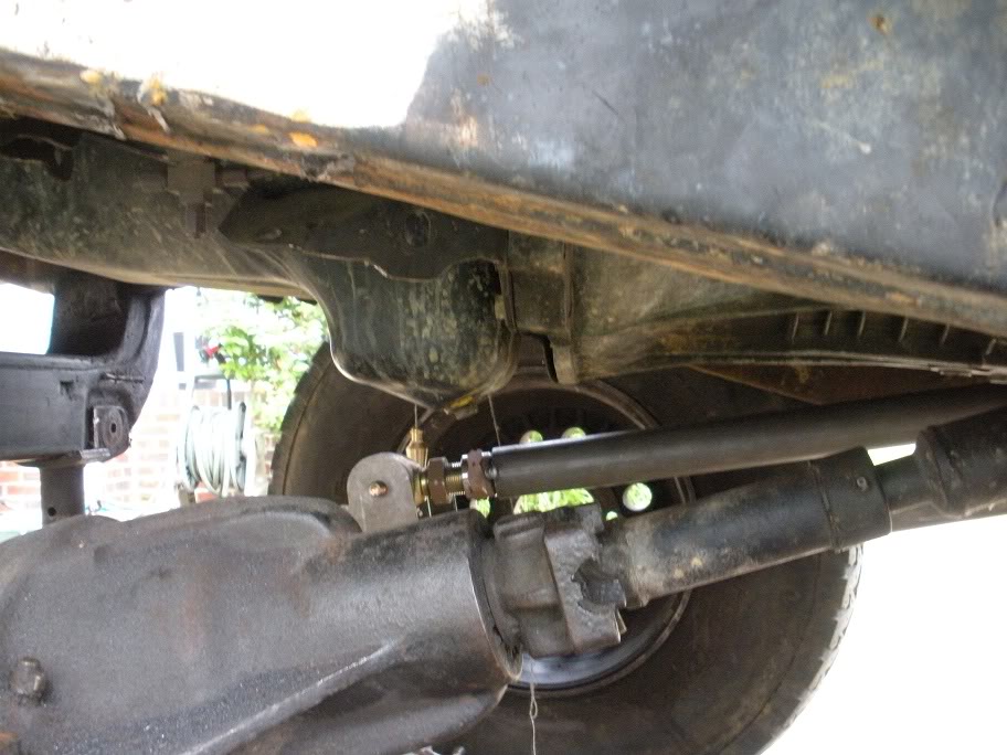
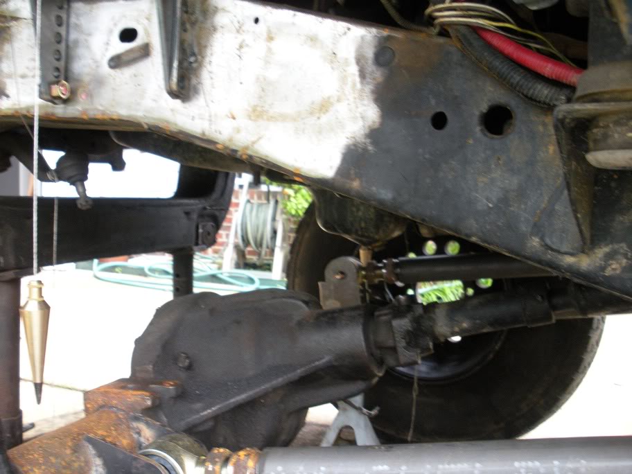
So now that the upper coil towers are mounted, the lower coil buckets need to be mounted. But, before they can be mounted, the pinion and castor angles need to be figured out and set up. If these aren't taken care of first, you could end up with the coil buckets sitting at odd angles later!
On a double cardan driveshaft, the pinion needs to be angled inline, or parallel (0 degrees) to the driveshaft. This is because the non-constant velocity rotational tendancies of of u-joint driveshafts are taken care of my the double-cardan joint and are not transferred through the entire driveshaft (if this statement makes no sense to you, you should do extensive research on driveline angles before attempting a project like this). The desired castor angle for a dana 44 solid front axle is -5-7 degrees, so with the pinion properly angled, the inner knuckle C's needs to be rotated to the desired castor angle.
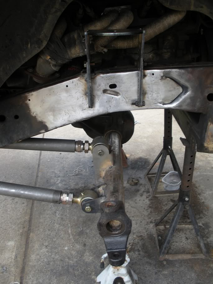
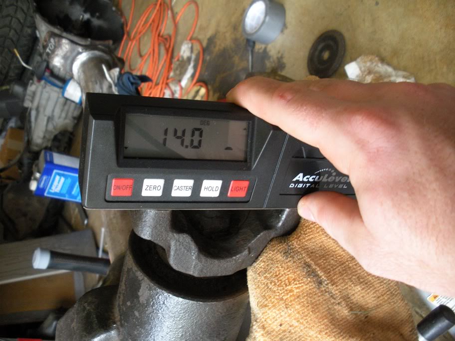
So I started by measuring out the axle to place it at ride height (or as close to ride height as I can estimate right now). I measured the rear axle sprung from centerline to the top of the wheel well and copied it on the front. Then I used my front driveshaft to eye the pinion angle. Because it's a double cardan driveshaft, and the pinion needs to be inline with the driveshaft, eyeing the pinion angle isn't hard. The pinion angle came out to be 14 degrees up.
On a double cardan driveshaft, the pinion needs to be angled inline, or parallel (0 degrees) to the driveshaft. This is because the non-constant velocity rotational tendancies of of u-joint driveshafts are taken care of my the double-cardan joint and are not transferred through the entire driveshaft (if this statement makes no sense to you, you should do extensive research on driveline angles before attempting a project like this). The desired castor angle for a dana 44 solid front axle is -5-7 degrees, so with the pinion properly angled, the inner knuckle C's needs to be rotated to the desired castor angle.
So I started by measuring out the axle to place it at ride height (or as close to ride height as I can estimate right now). I measured the rear axle sprung from centerline to the top of the wheel well and copied it on the front. Then I used my front driveshaft to eye the pinion angle. Because it's a double cardan driveshaft, and the pinion needs to be inline with the driveshaft, eyeing the pinion angle isn't hard. The pinion angle came out to be 14 degrees up.
Last edited by 95_318SLT; 06-01-2010 at 02:24 PM.
#23
05-24-2010, 06:01 PM
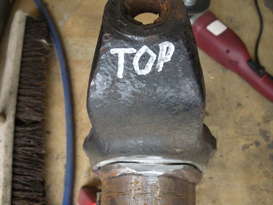
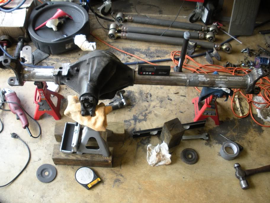
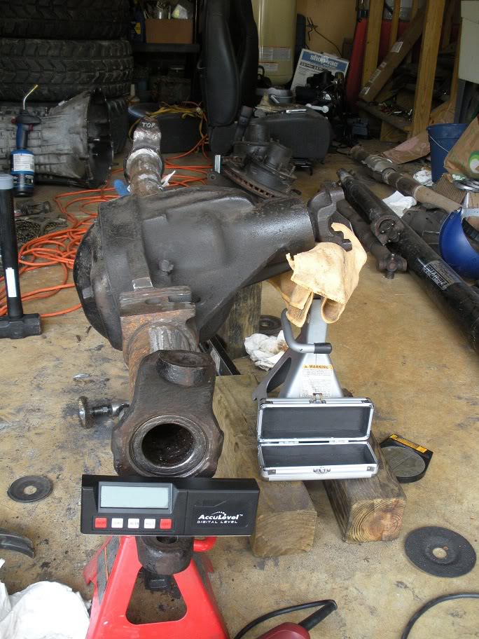
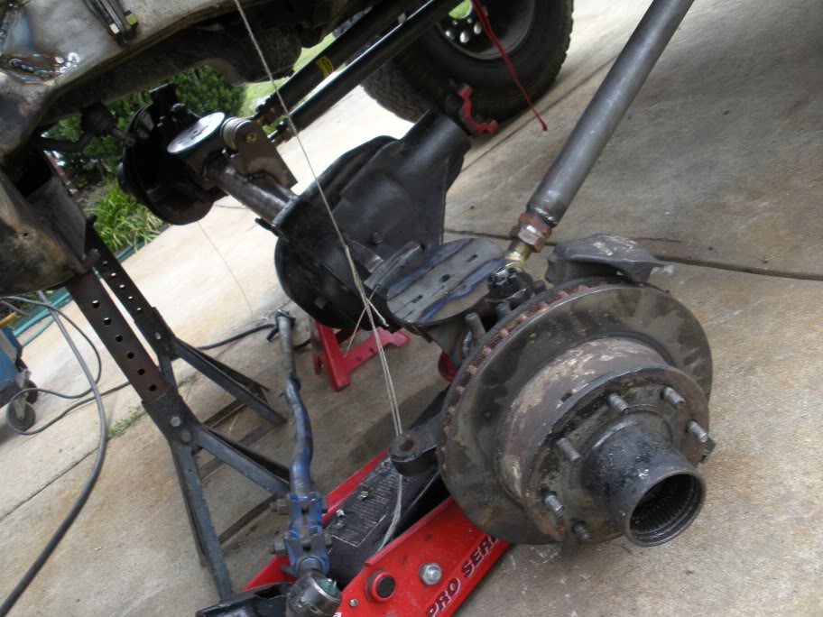
So with the angle known, the axle can come back out from under the truck. I set the axle up in the garage mocking the 14 degree pinion angle...
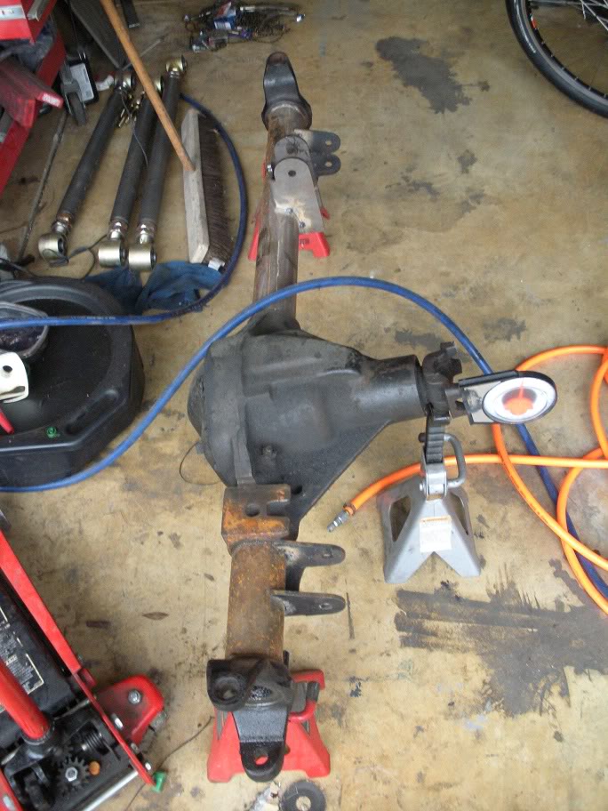
So where I stand now, if I were to set the castor at -6 degrees (middle of the desired range) with the pinion at 14 degrees up, I'd have a plus or minus 1-2 degree tolerance for fine tuning the axle later (once it actually has weight on it) while still keeping acceptable driveline, steering, and coil bucket angles.
With the axle set up on jackstands and the required angles figured out, the inner knuckle C's need to be removed. Since they are welded on, the welds just need to be ground off and the inner knuckle C's banged off with a BFH.
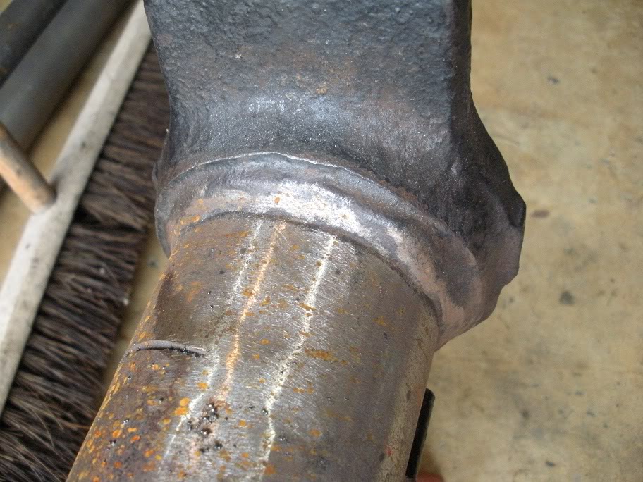
I made the first cut with my angle grinder...
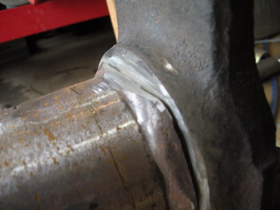
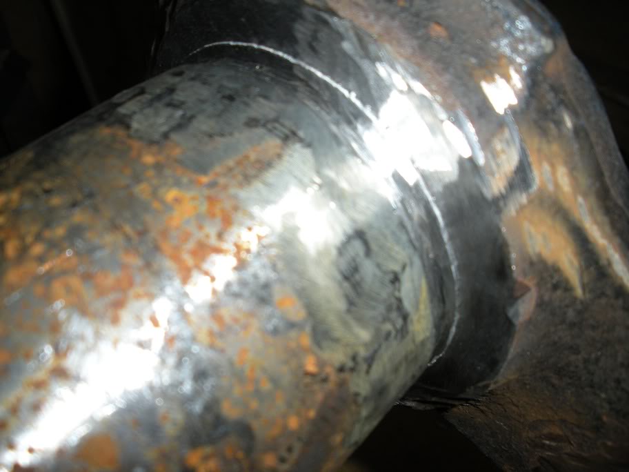
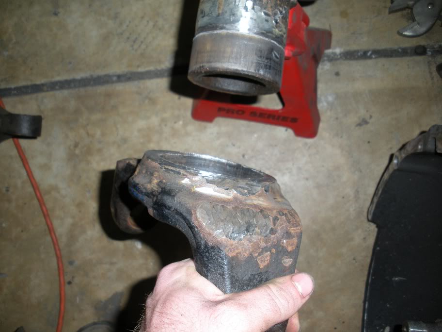
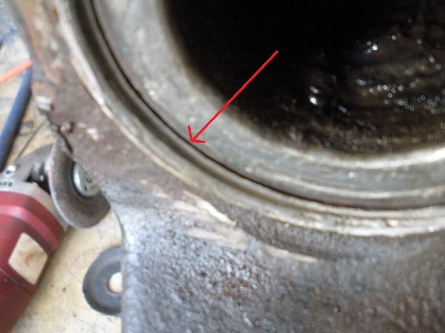
And then I ground down the rest of that weld. Once it was ground down, I started beating on it with a hammer. While beating on it, you need to look for the stress crack to form at the joint, and if it doesn't after a few hard blows, put the hammer down and do some more grinding!! Once the stress crack forms, you'll see this...
Then just drive it home with the BFH!!!
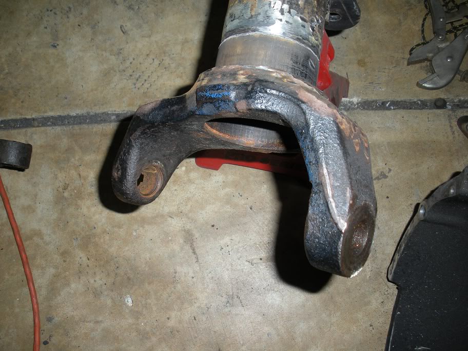
And then do the other side...
Now I just have to wait for the digital angle finder I ordered to get here. The castor needs to be set very accurately so the two sides aren't different! My angle finder you've seen in these pictures is just a cheap one with too much room for error, so I ordered a digital angle finder thats accurate to 1/10 of a degree. Yes, its an expensive angle finder, but its still cheaper than paying someone else to do it later!!!
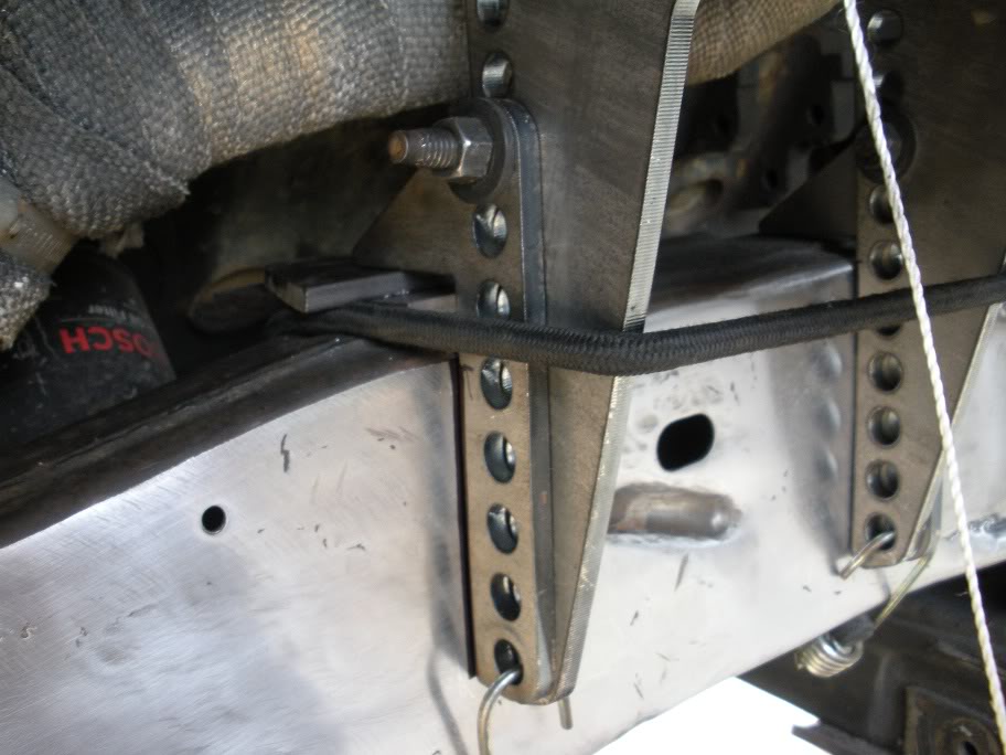
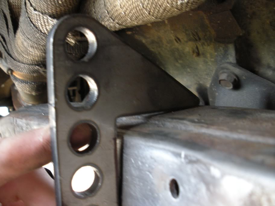
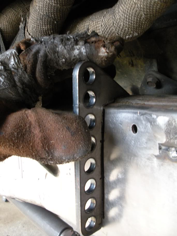
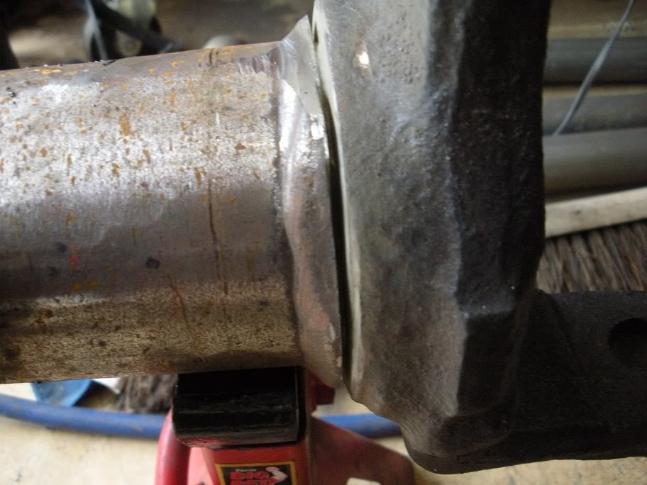
So while I wait, let me point out the upper link bracket on the axle. As you can see its sitting at an odd angle now... this is why it's important to just tack weld the mounts on... because it has to be cut off and turned again!
So where I stand now, if I were to set the castor at -6 degrees (middle of the desired range) with the pinion at 14 degrees up, I'd have a plus or minus 1-2 degree tolerance for fine tuning the axle later (once it actually has weight on it) while still keeping acceptable driveline, steering, and coil bucket angles.
With the axle set up on jackstands and the required angles figured out, the inner knuckle C's need to be removed. Since they are welded on, the welds just need to be ground off and the inner knuckle C's banged off with a BFH.
I made the first cut with my angle grinder...
And then I ground down the rest of that weld. Once it was ground down, I started beating on it with a hammer. While beating on it, you need to look for the stress crack to form at the joint, and if it doesn't after a few hard blows, put the hammer down and do some more grinding!! Once the stress crack forms, you'll see this...
Then just drive it home with the BFH!!!
And then do the other side...
Now I just have to wait for the digital angle finder I ordered to get here. The castor needs to be set very accurately so the two sides aren't different! My angle finder you've seen in these pictures is just a cheap one with too much room for error, so I ordered a digital angle finder thats accurate to 1/10 of a degree. Yes, its an expensive angle finder, but its still cheaper than paying someone else to do it later!!!
So while I wait, let me point out the upper link bracket on the axle. As you can see its sitting at an odd angle now... this is why it's important to just tack weld the mounts on... because it has to be cut off and turned again!
Last edited by 95_318SLT; 06-01-2010 at 02:28 PM.
#24
06-01-2010, 02:41 PM
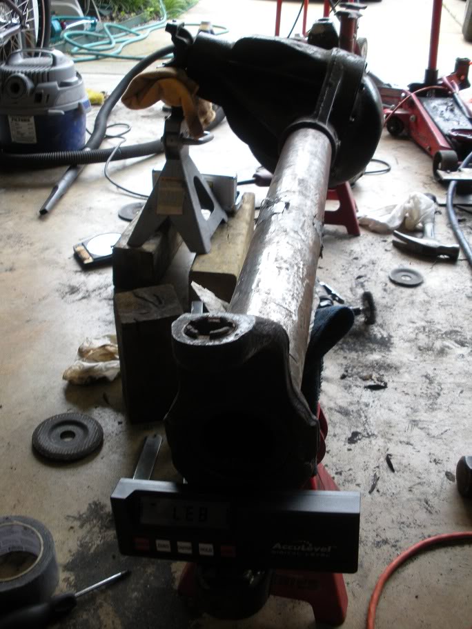
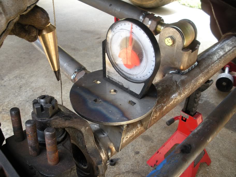
I finally got my angle finder and got the inner knuckle C's put back on.
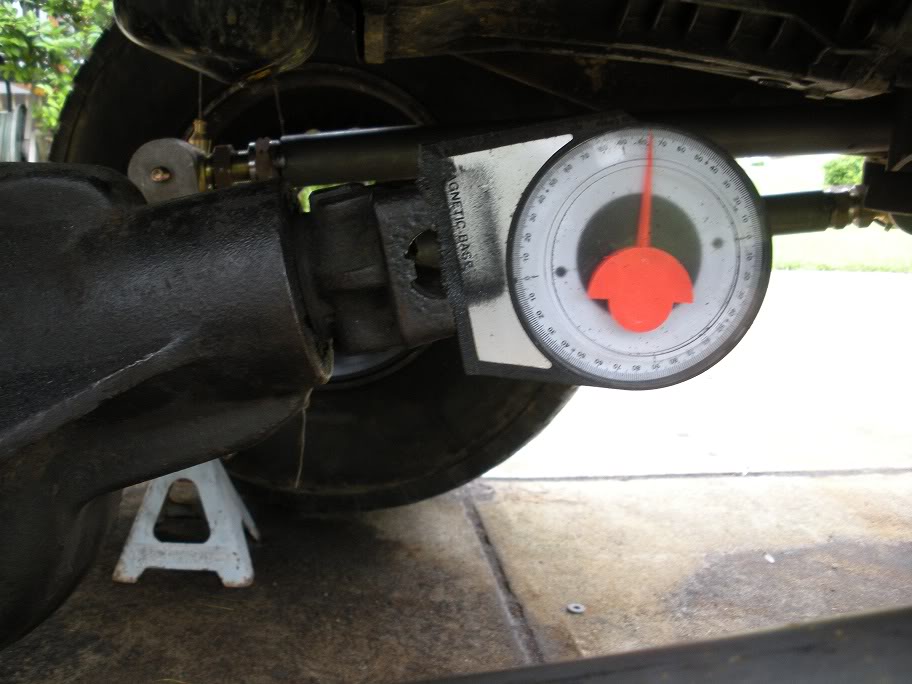
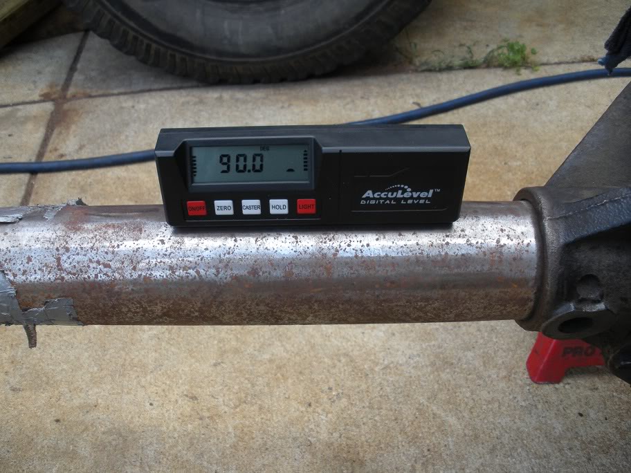
To start, I made sure the axle was level on its jackstands and the pinion 14 degrees up.
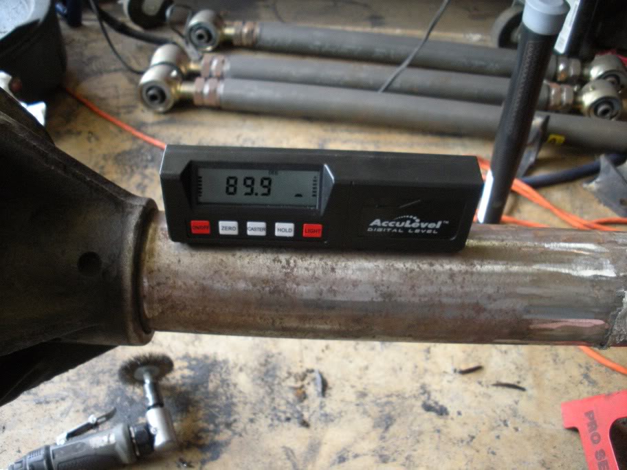
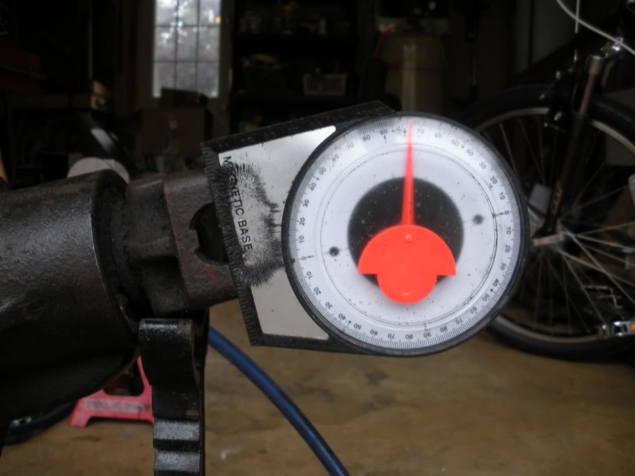
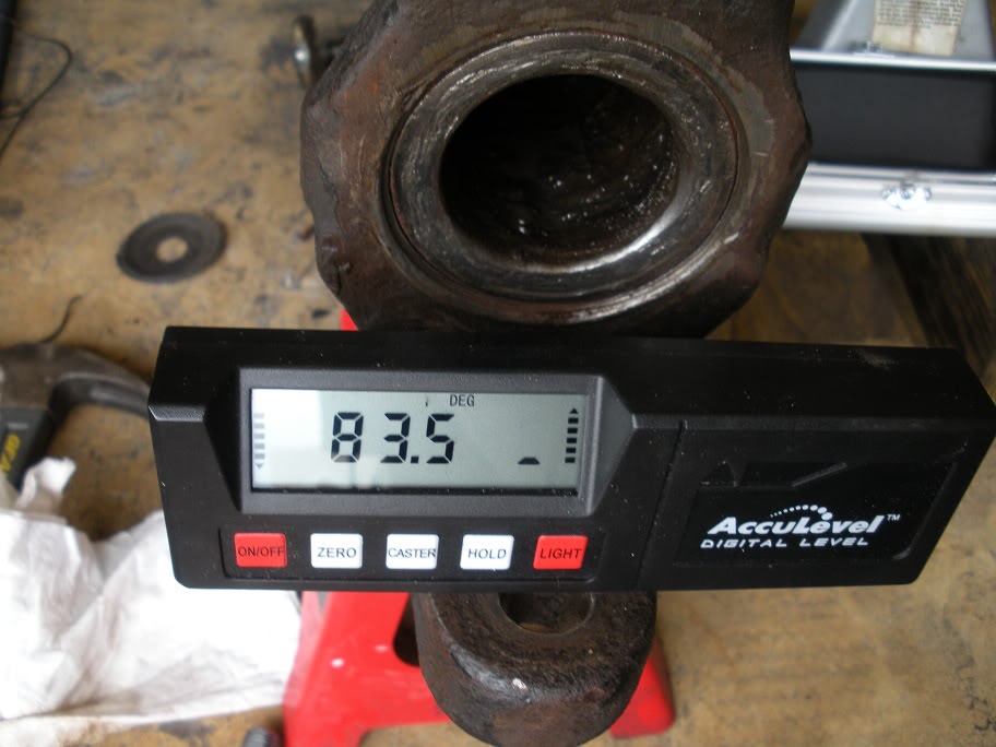
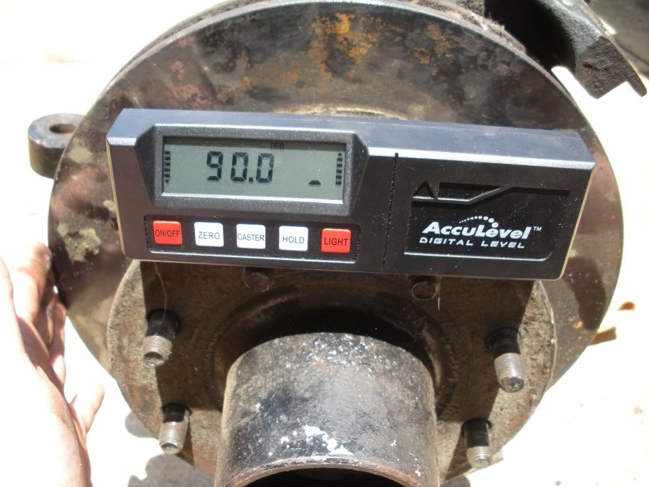
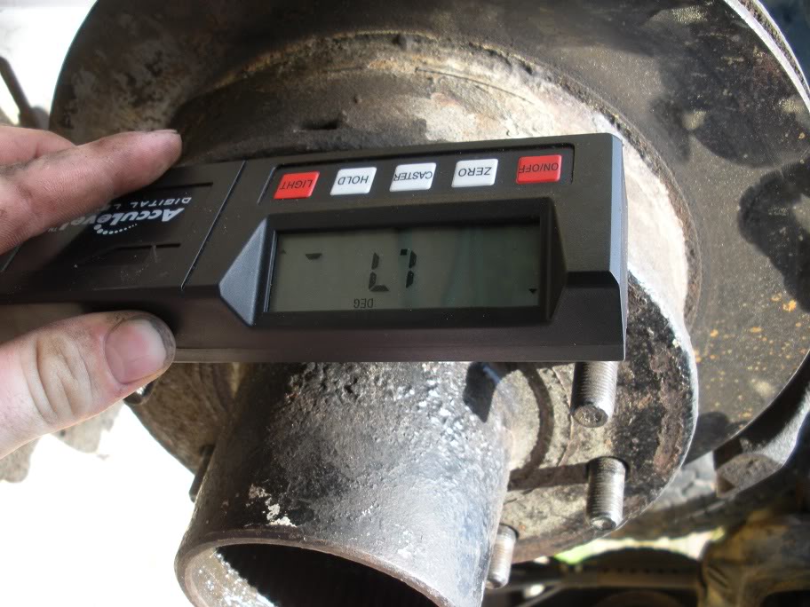
Next, I hammered the inner knucle C's on about an 1/8 of an inch and measured the angle. I used the flat part of the bottom of the C and put the edge of the angle finder against the lip to ensure both sides are measured the same.
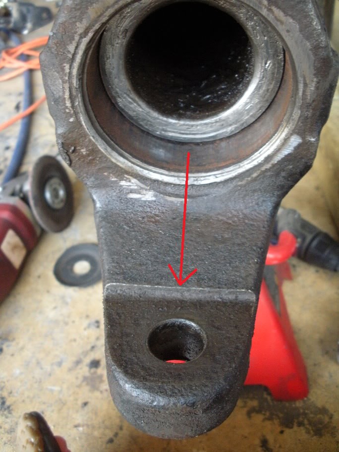
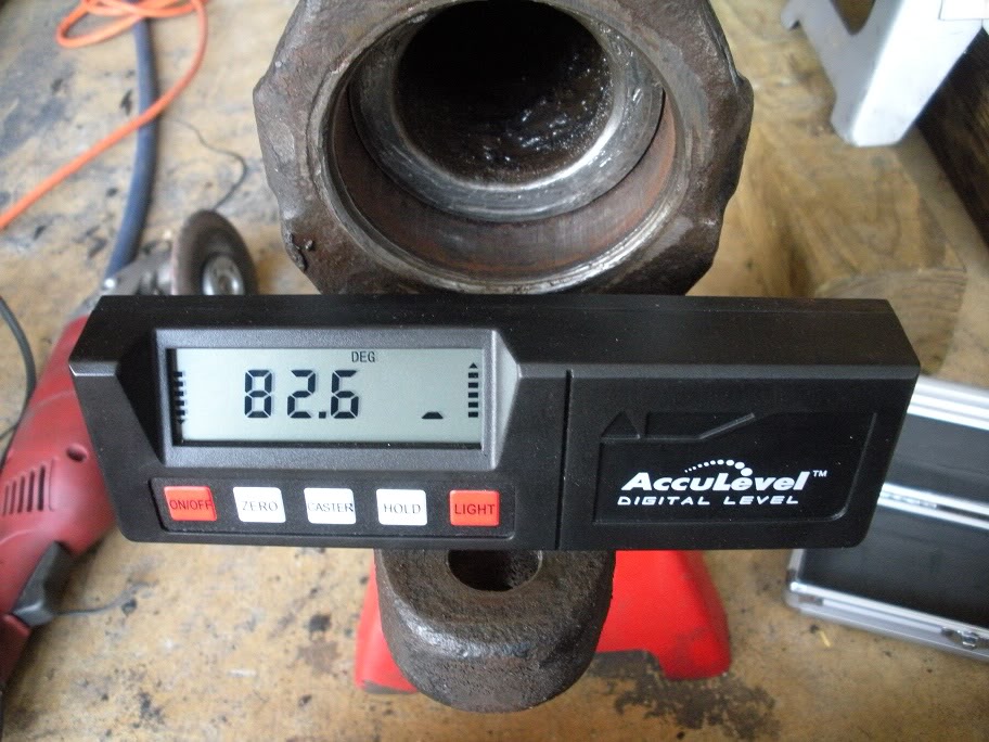
I turned them with a hammer until they were at 6 degrees (84 on the angle finder). Then I ran them home with the hammer. Once they are all the way on, use the lip on the inner knuckle C and the end of the axle tube to make sure they are straight.
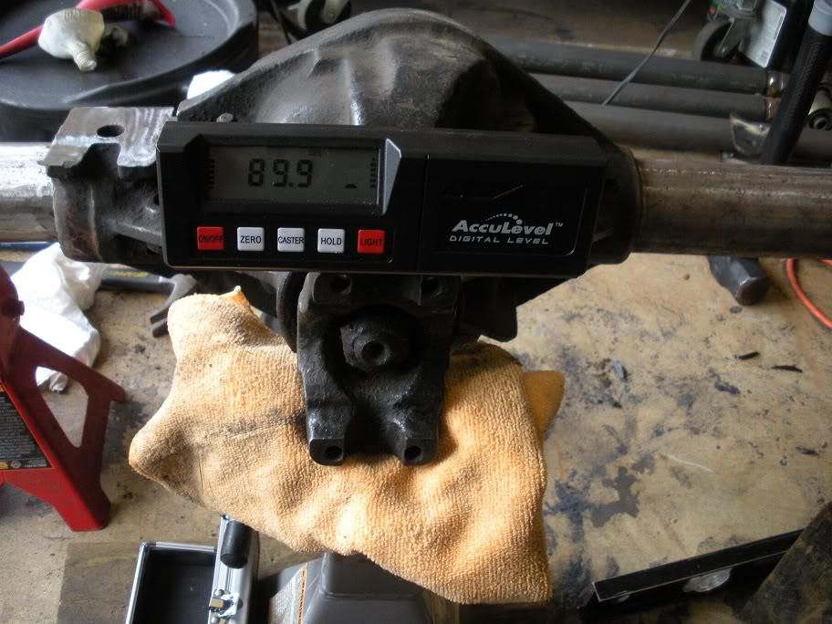
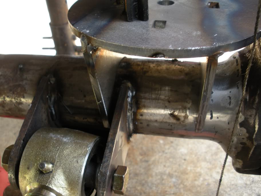
Next, I measured remeasured the castor angle to make sure they didn't turn as I was hammering them on.
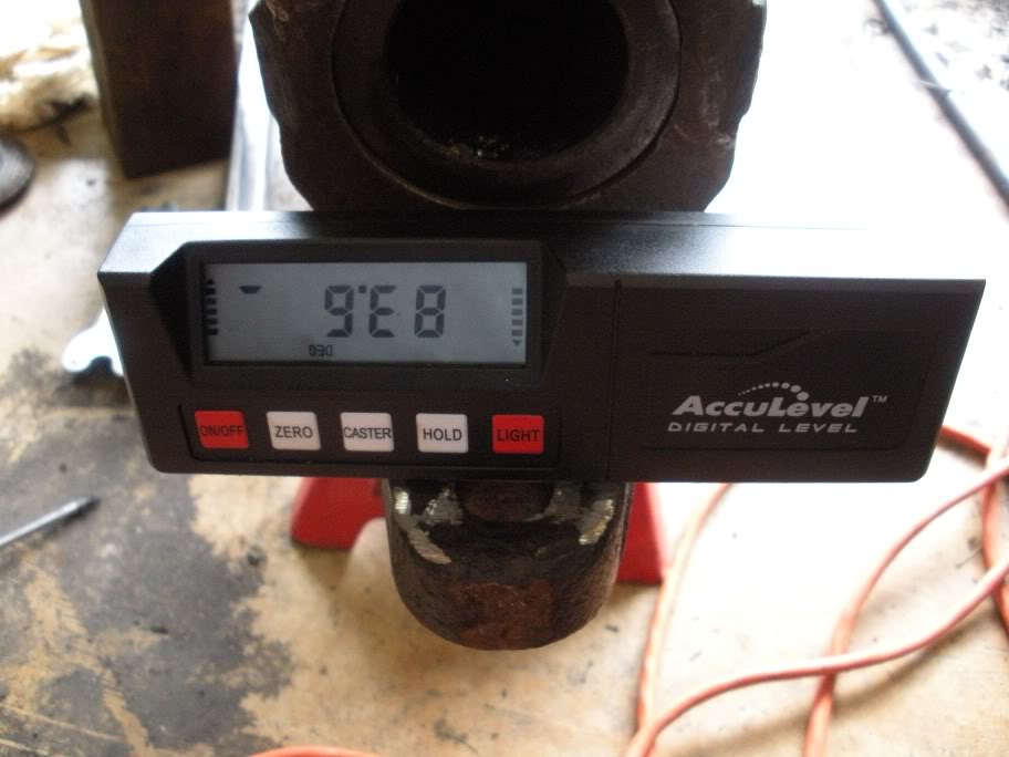
As you can see, they each turned a little bit. They came out to be around 6.5 degrees and within .1 degrees of each other, which is acceptable enough to not worry about redoing it.
Next, the brackets that were tacked on before need to be turned to the new axle angles.
To start, I made sure the axle was level on its jackstands and the pinion 14 degrees up.
Next, I hammered the inner knucle C's on about an 1/8 of an inch and measured the angle. I used the flat part of the bottom of the C and put the edge of the angle finder against the lip to ensure both sides are measured the same.
I turned them with a hammer until they were at 6 degrees (84 on the angle finder). Then I ran them home with the hammer. Once they are all the way on, use the lip on the inner knuckle C and the end of the axle tube to make sure they are straight.
Next, I measured remeasured the castor angle to make sure they didn't turn as I was hammering them on.
As you can see, they each turned a little bit. They came out to be around 6.5 degrees and within .1 degrees of each other, which is acceptable enough to not worry about redoing it.
Next, the brackets that were tacked on before need to be turned to the new axle angles.
#25
07-14-2010, 03:20 PM
Alright, finally got back to work on this project!!
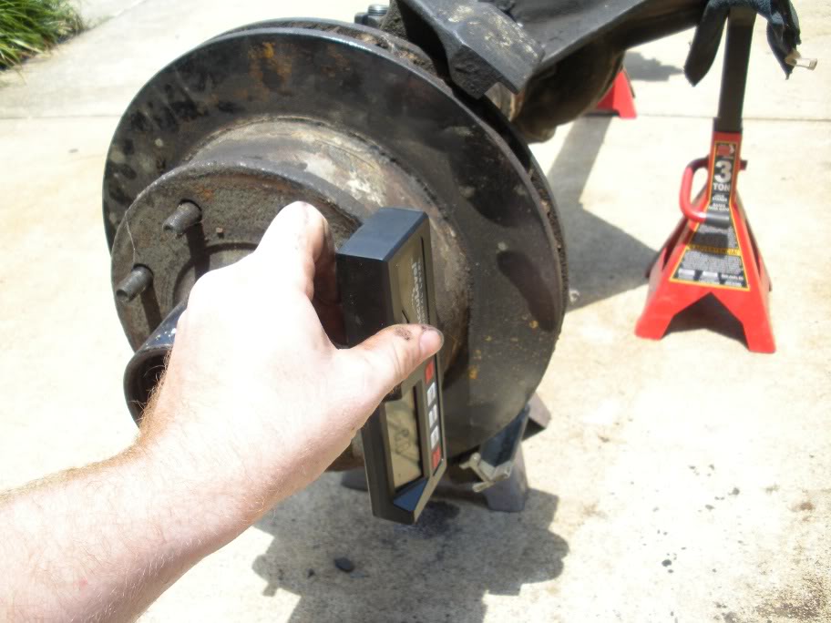
After setting the castor angle on the inner knuckles, the camber needs to be set. Toe is not as important because its adjustable via the tie rods. Now unfortunately, I didn't think about camber before I cut the brackets off, but luckily I bought that '78 F150 and measured the angle on it! But here is my procedure for setting the camber angle...
First, I found the desired angle on the F150 by jacking it up, taking off a tire, and making sure the axle was level. Once the axle is level, I aligned 2 consecutive lugs vertically...
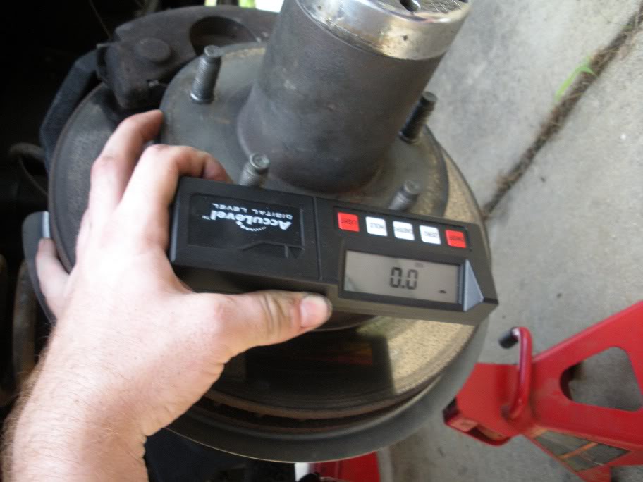
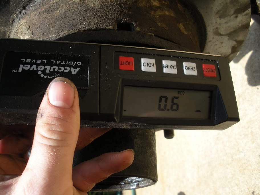
This gave me a vertical backrest for the level. So next, I laid the level against the hub, with the back against those 2 lug nutsl...
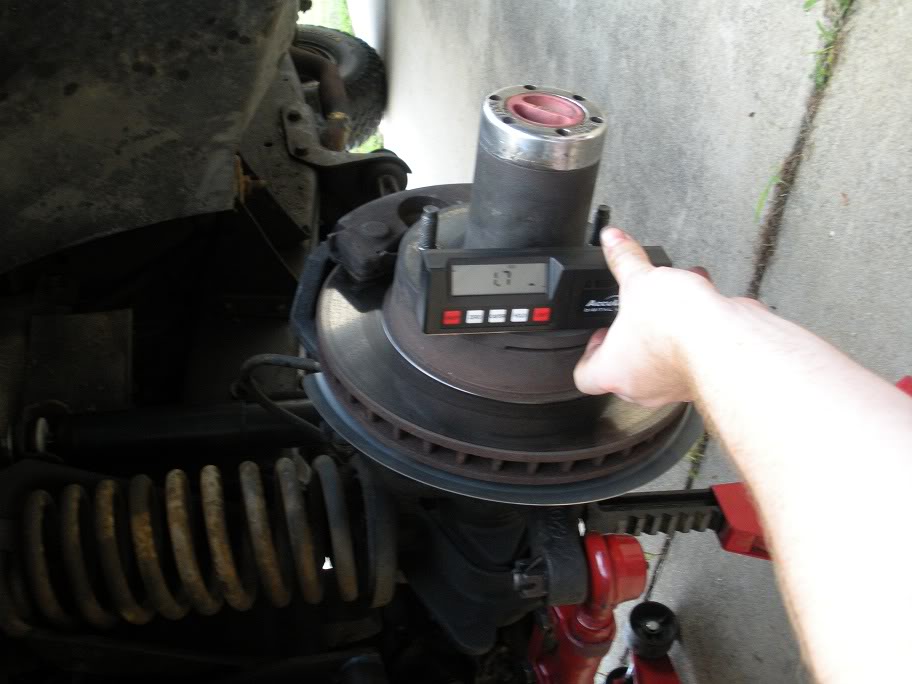
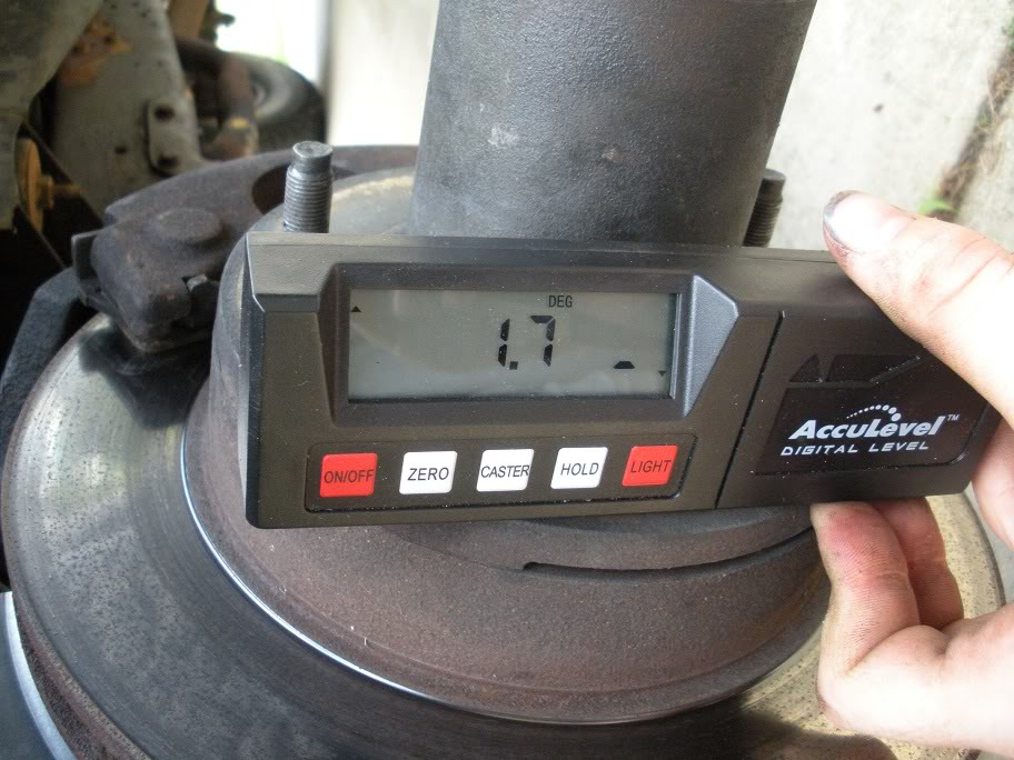
As you can see, the camber is 1.7 degrees top outward. I assume they did this so once weight is on it, it flexes toward 0, but thats just an assumption.
So now that I know the angle I want, I put the outer knuckles on the axle and leveled the axle out (it was moved around since last time I worked on it)...

Then I took initial measurements to see where they sit...
And then did the same on the other side.
As you can see, its nowhere near 1.7. So what I did was tack the c's on at the 3 and 9 oclock positions so the castor wouldn't change while I beat on them. Then I beat on them with the BFH and remeasured and repeated until it was 1.7 degrees...
So repeat that procedure for both sides, and then weld the inner knuckle C's on. I suggest doing this in multiple beads. I layed one down and grinded it smooth...
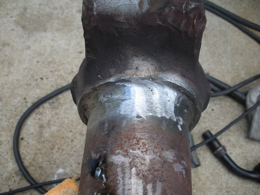
This is where I stopped to come inside and cool off. I'll continue to weld it later.
By the way, I'm using a 200 amp, 240 volt miller Welder with solid core wire and MIG gas. I borrowed the welder from a buddy who has been helping me the last couple nights to weld the various brackets I had tacked down. The axle should be ready tomorrow to be put in place!! More pictures to come...
After setting the castor angle on the inner knuckles, the camber needs to be set. Toe is not as important because its adjustable via the tie rods. Now unfortunately, I didn't think about camber before I cut the brackets off, but luckily I bought that '78 F150 and measured the angle on it! But here is my procedure for setting the camber angle...
First, I found the desired angle on the F150 by jacking it up, taking off a tire, and making sure the axle was level. Once the axle is level, I aligned 2 consecutive lugs vertically...
This gave me a vertical backrest for the level. So next, I laid the level against the hub, with the back against those 2 lug nutsl...
As you can see, the camber is 1.7 degrees top outward. I assume they did this so once weight is on it, it flexes toward 0, but thats just an assumption.
So now that I know the angle I want, I put the outer knuckles on the axle and leveled the axle out (it was moved around since last time I worked on it)...
Then I took initial measurements to see where they sit...
And then did the same on the other side.
As you can see, its nowhere near 1.7. So what I did was tack the c's on at the 3 and 9 oclock positions so the castor wouldn't change while I beat on them. Then I beat on them with the BFH and remeasured and repeated until it was 1.7 degrees...
So repeat that procedure for both sides, and then weld the inner knuckle C's on. I suggest doing this in multiple beads. I layed one down and grinded it smooth...
This is where I stopped to come inside and cool off. I'll continue to weld it later.
By the way, I'm using a 200 amp, 240 volt miller Welder with solid core wire and MIG gas. I borrowed the welder from a buddy who has been helping me the last couple nights to weld the various brackets I had tacked down. The axle should be ready tomorrow to be put in place!! More pictures to come...
#26
07-15-2010, 05:42 PM
Well I didn't get any pictures last night cause my buddy came over and we had to work hard and fast to get done what could be done last night. But we got everything but the coil buckets (axle side) done and the axle hung under the truck. I don't really think pictures are needed, cause there are plenty of other pictures of the previous test fits! But the axle was attached with all 3 links and the pinion angle set to 14 degrees.
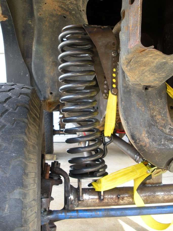
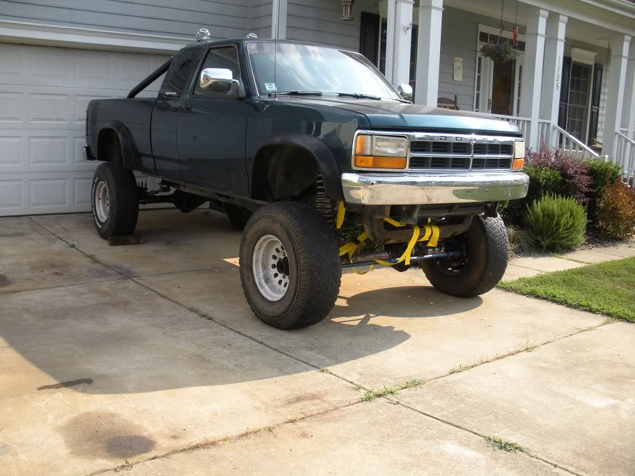
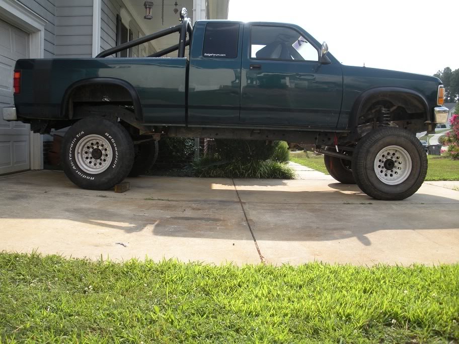
This morning I got the coil buckets made and welded onto the axle, got the coil springs in place and got the truck sitting on all 4 wheels!
Here are the coil buckets I made welded together...
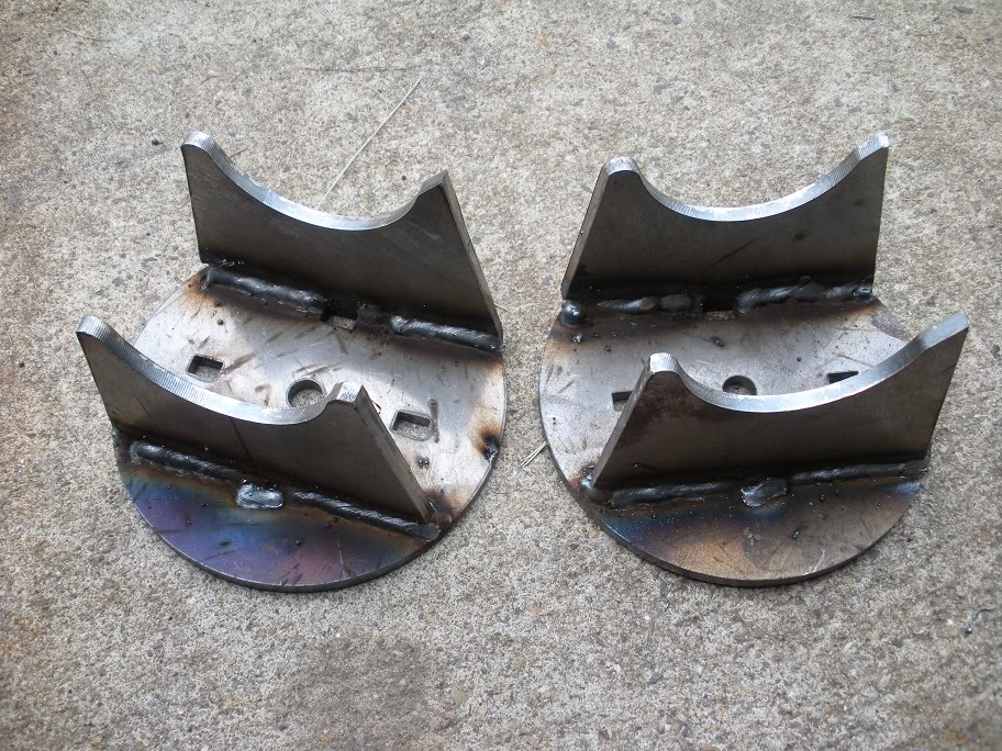
With the coil buckets made, I set them on the axle as far out as they could clear, which isn't quite far enough for how far the towers sit off the frame, buts its not off by much! Then I set my angle finder on them, leveled them out, and welded them on...

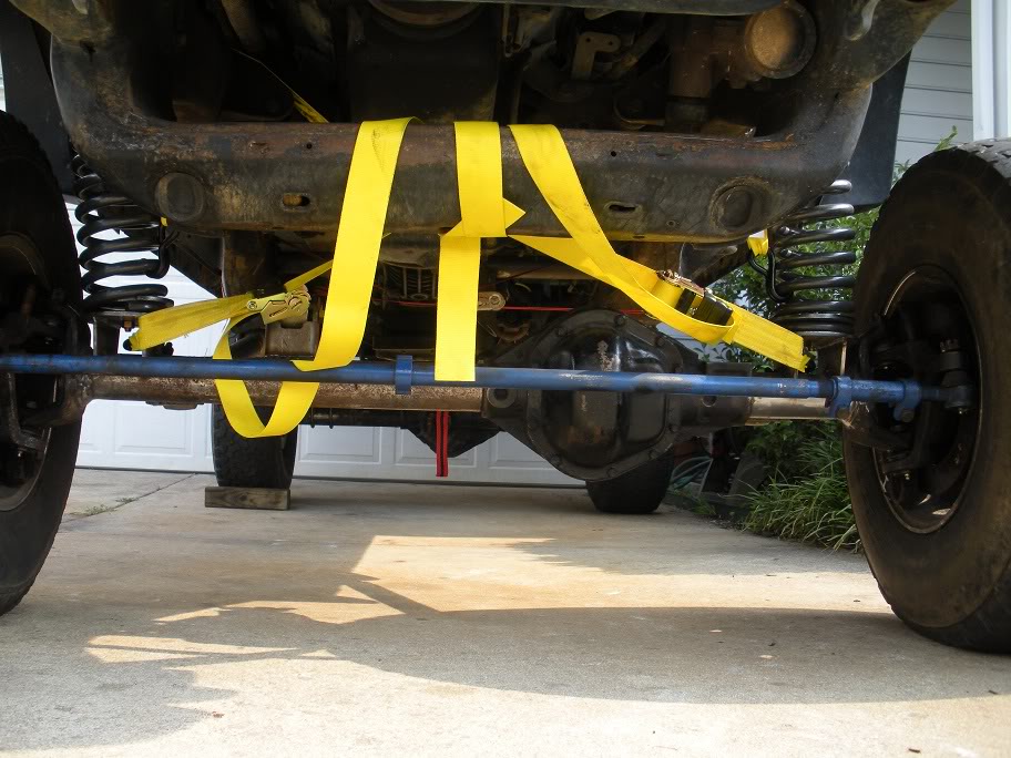
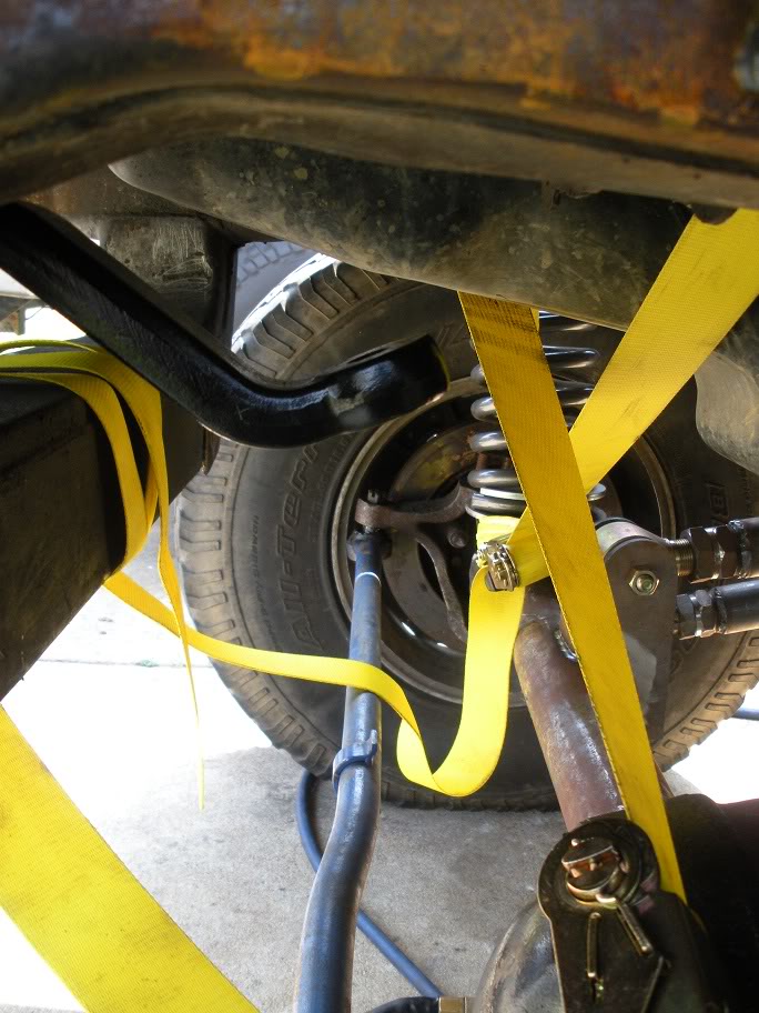
Then I put the springs in, used some ratchet straps as a temporary track bar, and got it sitting on all 4 wheels...
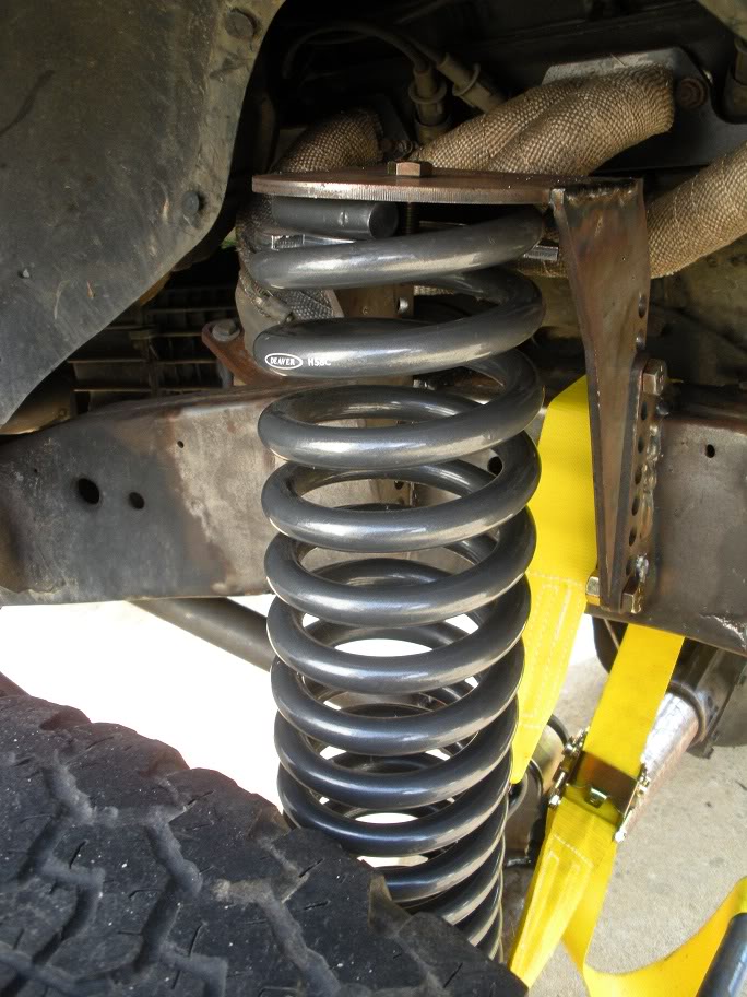
(The spring won't be bent this far, but the truck is shifted to one side right now cause I couldn't get the ratchet straps perfectly even.....)
This morning I got the coil buckets made and welded onto the axle, got the coil springs in place and got the truck sitting on all 4 wheels!
Here are the coil buckets I made welded together...
With the coil buckets made, I set them on the axle as far out as they could clear, which isn't quite far enough for how far the towers sit off the frame, buts its not off by much! Then I set my angle finder on them, leveled them out, and welded them on...
Then I put the springs in, used some ratchet straps as a temporary track bar, and got it sitting on all 4 wheels...
(The spring won't be bent this far, but the truck is shifted to one side right now cause I couldn't get the ratchet straps perfectly even.....)
Last edited by 95_318SLT; 07-23-2010 at 12:57 PM.
#27
07-23-2010, 01:11 PM
Now its time for steering! It's important to get the steering setup before the trackbar, so that the trackbar can be set up to compliment the drag link to avoid bump steer. The drag link and track bar's path of travel (which would form an arc if you drew it) need to be parallel to each other to avoid bump steer, and the drag link has to be placed in a particular spot, whereas the track bar mounts can be made however you need to make them.
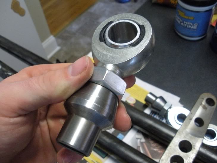
Anway, I've decided to use a custom-built heim joint steering system using 7/8s heim joints for the rod ends and 1/4 inch walled DOM tubing for the link bars. Should make for bullet-proof steering links! I am also using high steer arms. I ordered the steering kit and steering arms from BallisticFabrication.com. The kit was cheaper than trying to peice it together myself, and that site is running a 15% off sale this week!
http://www.ballisticfabrication.com/...re_p_1248.html
http://www.ballisticfabrication.com/...rs_p_1337.html
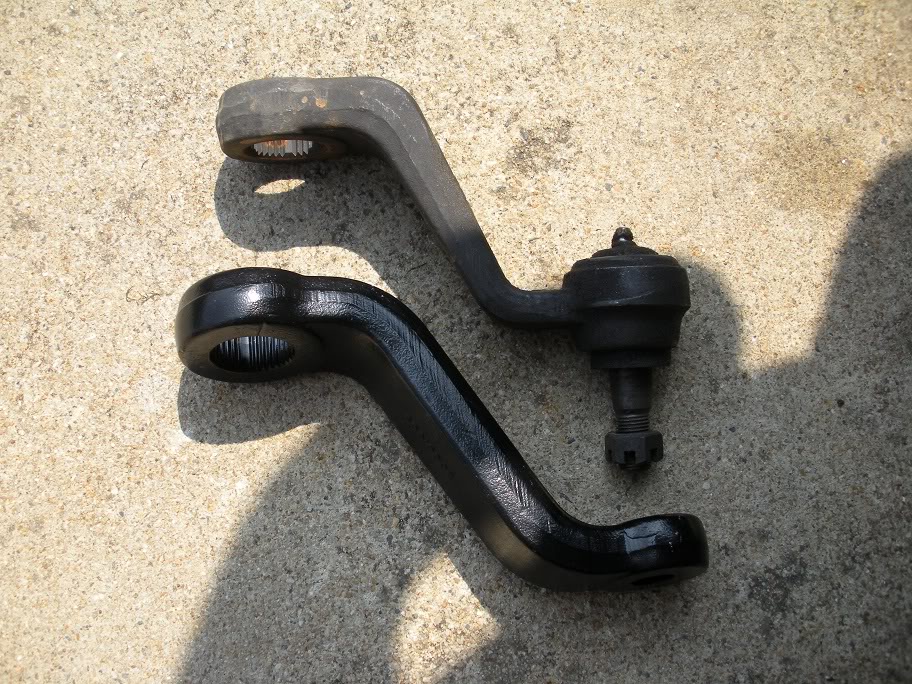
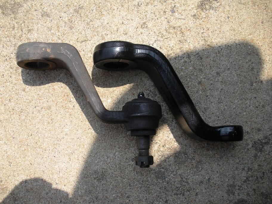
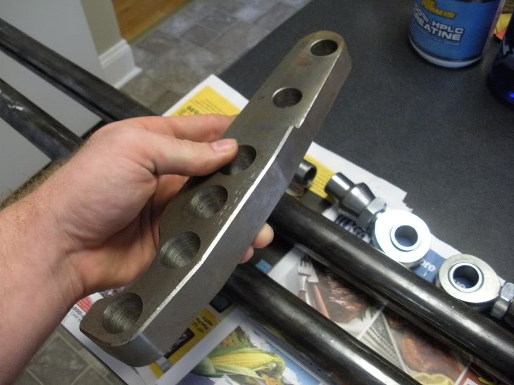
Anyway, the order was custom order (I wanted the high steer arms drilled out for the heim joints), so it might be a week or two before it gets here. In the meantime, I researched what kind of pitman arm to use. Our pitman arms have a TRE built in, and I just want a hole. A looked on NAPA.com (since they give measurements of all their parts), and found out that a Jeep TJ Wrangler has basically the same steering box as our trucks do, so I ordered an aftermarket drop pitman arm for a TJ. Here are pictures of them side by side...
Since this pitman arm is tapered, I'm going to have to get it drilled out to 3/4 of an inch for the heim joints, but it fits. Here are some pics of my test fit...
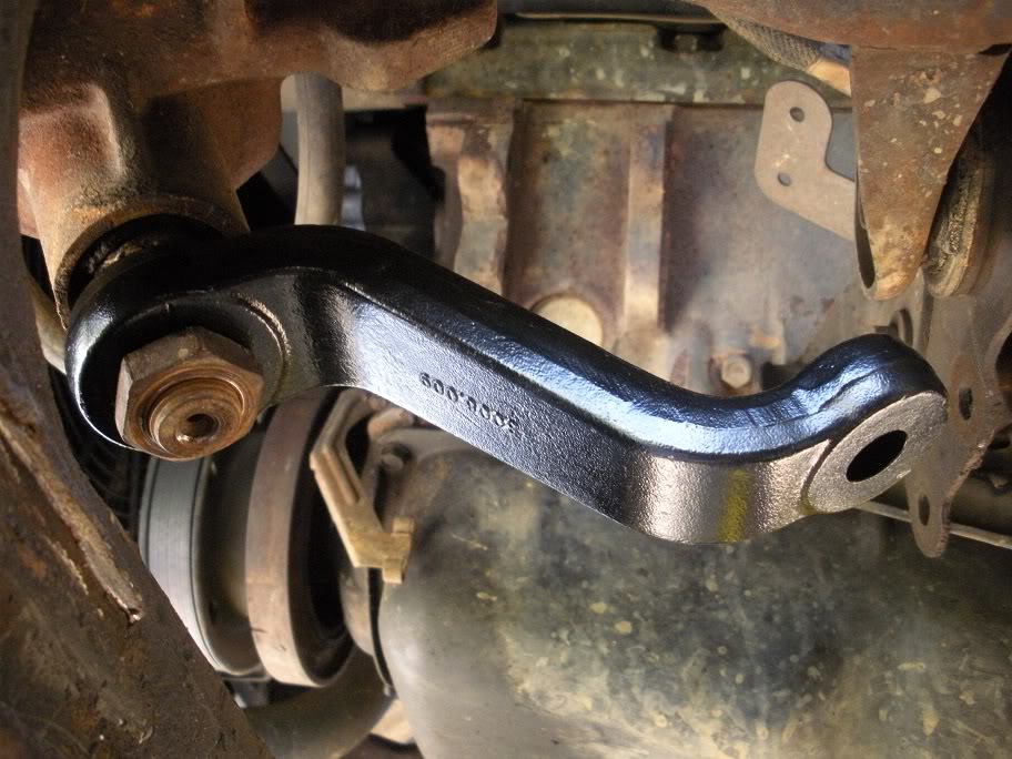
(below you can see how well the pitman arm lines up with the steering knucle!!)
Instead of trying to drill that sucker out myself (although I have a drill press), I'm going to let a machine shop do it. I don't have a good way of clamping it flat on the press. So I'm going to drop it off on monday to get it drilled out and then bolt it onto the steering box and wait for the rest of my parts to show up.
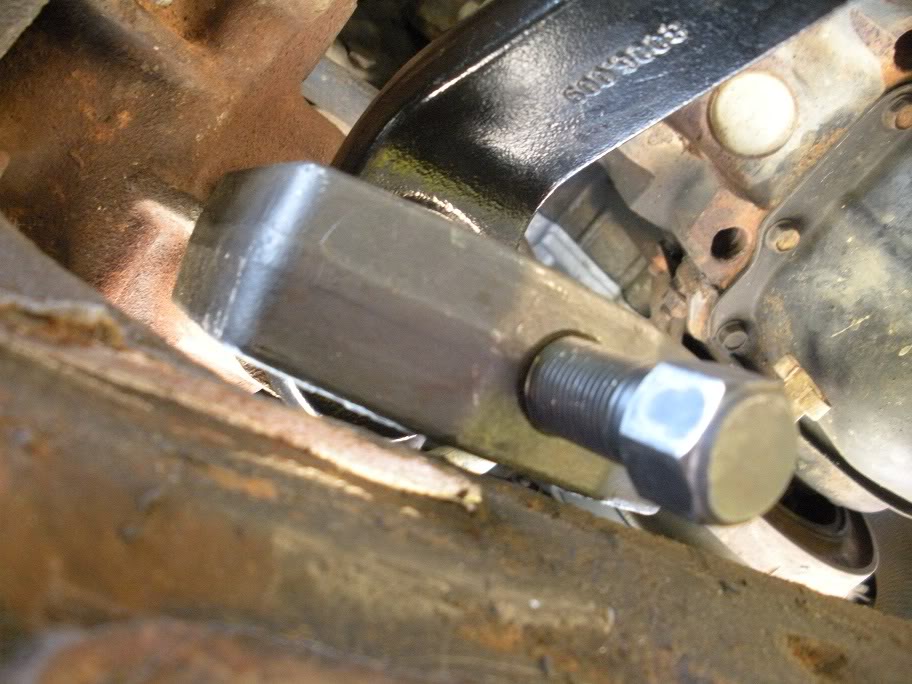
By the way, as a side note to anyone who has ever tried to pull a pitman arm off our trucks... Losing the factory suspension and mounts makes it very easy to put a pitman arm puller in place!!
Anway, I've decided to use a custom-built heim joint steering system using 7/8s heim joints for the rod ends and 1/4 inch walled DOM tubing for the link bars. Should make for bullet-proof steering links! I am also using high steer arms. I ordered the steering kit and steering arms from BallisticFabrication.com. The kit was cheaper than trying to peice it together myself, and that site is running a 15% off sale this week!
http://www.ballisticfabrication.com/...re_p_1248.html
http://www.ballisticfabrication.com/...rs_p_1337.html
Anyway, the order was custom order (I wanted the high steer arms drilled out for the heim joints), so it might be a week or two before it gets here. In the meantime, I researched what kind of pitman arm to use. Our pitman arms have a TRE built in, and I just want a hole. A looked on NAPA.com (since they give measurements of all their parts), and found out that a Jeep TJ Wrangler has basically the same steering box as our trucks do, so I ordered an aftermarket drop pitman arm for a TJ. Here are pictures of them side by side...
Since this pitman arm is tapered, I'm going to have to get it drilled out to 3/4 of an inch for the heim joints, but it fits. Here are some pics of my test fit...
(below you can see how well the pitman arm lines up with the steering knucle!!)
Instead of trying to drill that sucker out myself (although I have a drill press), I'm going to let a machine shop do it. I don't have a good way of clamping it flat on the press. So I'm going to drop it off on monday to get it drilled out and then bolt it onto the steering box and wait for the rest of my parts to show up.
By the way, as a side note to anyone who has ever tried to pull a pitman arm off our trucks... Losing the factory suspension and mounts makes it very easy to put a pitman arm puller in place!!
Last edited by 95_318SLT; 07-23-2010 at 01:13 PM.
#28
08-18-2010, 04:21 PM
Well I finally got the rest of my steering parts (almost). Needless to say, I'm very pissed off at the place I ordered them from. First, after almost 3 full weeks of not hearing from them, I give them a call and ask why my order hadn't been shipped. They say some BS about one of the parts was on backorder, but then they ship it out the very next day!... backorder my ***. They probably forgot about the order and had to be reminded about it!!! So I finally got the parts yesterday and the high steer arms aren't drilled out to 3/4 of an inch like the should be, so I called them back and they should be sending me new ones. We'll see how long that takes.
But anyway, even though the arms are wrong, I can still use them to take measurements until the right ones get here so I can cut and weld the links. Here are a few pictures of the parts. I don't have much time to work on it until the weekend, but I'll get more pictures then.

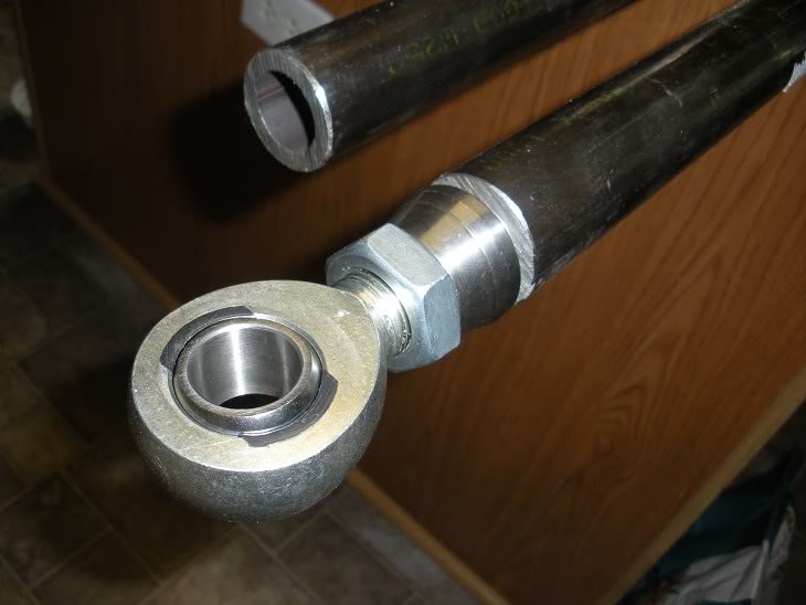
But anyway, even though the arms are wrong, I can still use them to take measurements until the right ones get here so I can cut and weld the links. Here are a few pictures of the parts. I don't have much time to work on it until the weekend, but I'll get more pictures then.
Last edited by 95_318SLT; 08-18-2010 at 04:24 PM.