

Bad transmission leak HELP PLZ!!!
#1
 05-29-2011, 01:39 PM


Join Date: Sep 2010
Posts: 7
Likes: 0
Received 0 Likes
on
0 Posts
hello all , i am not quite sure I am writing this at the right place , if not I am sorry , I have a bad leak coming from my trany , I have a 5.9 dodge durango mechanics , automatic transmission .
for sure it is the seal between the tork and the pump , I guess .
people say that automatically my tork and my pump is scrap .
is this true ?
and also where may I find a detailed how to fix this .
I would greatly appreciate any help ... lol I'm desperate lol.. thank you in advance .
for sure it is the seal between the tork and the pump , I guess .
people say that automatically my tork and my pump is scrap .
is this true ?
and also where may I find a detailed how to fix this .
I would greatly appreciate any help ... lol I'm desperate lol.. thank you in advance .
#2
05-29-2011, 03:14 PM

Rookie
Join Date: Jul 2010
Location: Oklahoma
Posts: 93
Likes: 0
Received 0 Likes
on
0 Posts
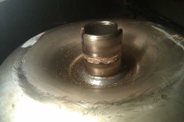
Good chance theyre right. When I got mine, I got it cheap because of that problem. I pulled the trans, thinking all I needed was a front pump seal. Torque converter wouldnt come out, had to pry it out. The pump bushing had seized up on the torque converter snout and tore up the surface of the pump housing as well. I lucked out, being a known mechanic, and knowing some people, I took it to an Aamco trans shop and they happened to have a good used pump for it, parts/seals and install was $50, I went through a transmission parts supply store and got the TC for like $160.
If you pull the trans yourself, make sure you have plenty of time ( 2-3 days) if doing it alone without lift, or air tools, etc. The crossmember is a bitch, you'll need to beat it towards the back to get it out, then use a tire iron on one side and a sledge hammer to beat it back forward going back in. other than that, its pretty straight forward. Wish I could bring you better news, but thats what it boils down to.
This was all before I got my current job, so now it would be a lot easier with lifts, proper tools, and a transmission guy in my shop. Our trans guy happens to be a dodge/GM trans tech.
Also, if you do end up pulling and reinstalling yourself, the inspection sheild is a c*nt, I left mine out, been fine, even offroading for over 10K miles so far. You'll be able to see what I mean. The previous owner actually tried to jb weld the cover seam where it meets the trans to stop the leak ..... If you need any help, just send me a message and I'll do what I can.
Last edited by oklahomafbody; 05-29-2011 at 03:17 PM.
#3
05-29-2011, 03:30 PM
Join Date: Sep 2010
Posts: 7
Likes: 0
Received 0 Likes
on
0 Posts
aright thanks , no good news then .. lol... apart that the mecanics is in a 97 grand cherokee so no problem with the cross member lol... so basicly I should take down the trany befor buying anything , then inspect damage , and I will most likly need a tork converter , a seal , and a new trans pump right ?  so I sould expect like a 500$ fix if I do it myself ???
or I pray that the pump is ok ... and I just have to change the tork converter and the seal ... cheap fix ... lol...
so I sould expect like a 500$ fix if I do it myself ???or I pray that the pump is ok ... and I just have to change the tork converter and the seal ... cheap fix ... lol...
#4
05-29-2011, 05:09 PM
Rookie
Join Date: Jul 2010
Location: Oklahoma
Posts: 93
Likes: 0
Received 0 Likes
on
0 Posts
I had about $250-$275 in it doing it myself, except for having the pump changed, etc, but good cheap shop and used pump was only $50. I would say, you could probably change the pump yourself if your comfortable with it, shouldnt be hard, I just didnt want to mess with it, I do everything but internal transmission lol. That price was with the new ATF+4 also. Changed transfer case fluid too.
Last edited by oklahomafbody; 05-29-2011 at 05:16 PM.
#5
05-29-2011, 05:13 PM
Join Date: Apr 2007
Location: Near Sacramento,ca
Posts: 11,545
Likes: 0
Received 92 Likes
on
78 Posts
Rick
You are right, You should always remove and inspect before replacing any parts. once you get the torque converter off, you may see the fluid leaking from around the front pump. A gasket package may cost under 100.00 bucks. Also replace all front pump bolts too. One other thing about changing the pump gasket. Be careful, because you can pull the pump and the input shaft out and the clutches would be misalign.
You are right, You should always remove and inspect before replacing any parts. once you get the torque converter off, you may see the fluid leaking from around the front pump. A gasket package may cost under 100.00 bucks. Also replace all front pump bolts too. One other thing about changing the pump gasket. Be careful, because you can pull the pump and the input shaft out and the clutches would be misalign.
Last edited by master tech; 05-29-2011 at 05:15 PM.
#6
05-29-2011, 05:26 PM
Rookie
Join Date: Jul 2010
Location: Oklahoma
Posts: 93
Likes: 0
Received 0 Likes
on
0 Posts
#7
05-29-2011, 05:32 PM
Join Date: Apr 2007
Location: Near Sacramento,ca
Posts: 11,545
Likes: 0
Received 92 Likes
on
78 Posts
Trending Topics
#8
05-29-2011, 05:40 PM
Join Date: Sep 2010
Posts: 7
Likes: 0
Received 0 Likes
on
0 Posts
Aright thanks guys , I appreciate your help very much ,how do I know if the pump is scrap ...and um in the event that I would have to change the pump , do you guys know where I can find detailed instructions ? I would like to do it myself , since so far I pretty much took apart my truck and rebuilt it by myself .
learning on the spot , with the help of forums lol.. thank got there are great people on forums . lol
By the way , when I put oil in , the trany works great ... like a new trany lol... but leaks bad ... thought it was important top mention it
its a grand cherokee 97
work done so far (Done in 2010)
33''x12.5'' widetrack tires -
15''rims
4.5'' roughCountry flex lift kit (Nitro shock upgrade)
RoughCountry 2''Wheel Spacers -
skyjacker shock ( direction) -
Headman Headers -
Flowmaster duel exaust
costom exaust line -
5.9 Dodge Magnum engin -
5.9 Dodge transmition and (S.T)T-case -
C-B Radio -
Costom center counsel. -
costom front & rear driveshaft .
#9
05-29-2011, 10:06 PM
Join Date: Apr 2007
Location: Near Sacramento,ca
Posts: 11,545
Likes: 0
Received 92 Likes
on
78 Posts
Here you go. Hope this is what you were looking for.In most case's this is how all the transmissions come apart. Doesn't matter if its a durango,jeep or a ram truck.
TRANSMISSION
DISASSEMBLY
1.Clean transmission exterior with steam gun or with solvent. Wear eye protection during cleaning operations.
2.Place transmission in a vertical position.
3.Measure and record input shaft end play readings.
4.Remove shift and throttle levers from valve body manual lever shaft.
5.Place transmission in horizontal position.
6.Remove transmission oil pan and gasket.
7.Remove filter from valve body Keep filter screws separate from other valve body screws. Filter screws are longer and should be kept with filter.
Oil Filter Removal
8.Remove park/neutral position switch.
9.Remove hex head bolts attaching valve body to transmission case A total of 10 bolts are used. Note different bolt lengths for assembly reference.
10.Remove valve body assembly. Push valve body harness connector out of case. Then work park rod and valve body out of case
11.Remove accumulator piston and inner and outer springs
12.Remove pump oil seal with suitable pry tool or slide-hammer mounted screw.
Valve Body Bolt Locations
Valve Body Removal
Accumulator Piston And Springs
13.Loosen front band adjusting screw locknut 4-5 turns. Then tighten band adjusting screw until band is tight around front clutch retainer. This prevents front/rear clutches from coming out with pump and possibly damaging clutch or pump components.
14.Remove oil pump bolts.
15.Thread bolts of Slide Hammer Tools C-3752 into threaded holes in pump body flange
16.Bump slide hammer weights outward to remove pump and reaction shaft support assembly from case
Removing Oil Pump And Reaction Shaft Support Assembly
17.Loosen front band adjusting screw until band is completely loose.
18.Squeeze front band together and remove band strut
19.Remove front band lever
20.Remove front band lever shaft plug, if necessary, from converter housing.
21.Remove front band lever shaft.
Removing/Installing Front Band Strut
Removing/Installing Front Band Lever
22.Remove front and rear clutch units as assembly. Grasp input shaft, hold clutch units together and remove them from case
23.Lift front clutch off rear clutch Set clutch units aside for overhaul.
Removing Front/Rear Clutch Assemblies
Separating Front/Rear Clutch Assemblies
24.Remove intermediate shaft thrust washer from front end of shaft or from rear clutch hub
25.Remove output shaft thrust plate from intermediate shaft hub
26.Slide front band off driving shell and remove band from case.
Removing Intermediate Shaft Thrust Washer
Removing Intermediate Shaft Thrust Plate
Front Band Removal/Installation
27.Remove planetary geartrain as assembly Support geartrain with both hands during removal. Do not allow machined surfaces on intermediate shaft or overdrive piston retainer to become nicked or scratched.
28.If overdrive unit is not to be serviced, install Alignment Shaft 6227-2 into the overdrive unit to prevent misalignment of the overdrive clutches during service of main transmission components.
29.Loosen rear band adjusting screw 4-5 turns.
30.Remove low-reverse drum snap ring
Removing Planetary Geartrain And Intermediate Shaft Assembly
Removing Low-Reverse Drum Snap Ring
31.Remove low-reverse drum and reverse band.
32.Remove overrunning clutch roller and spring assembly as a unit
33.Compress front servo rod guide about 1/8 inch with Valve Spring Compressor C-3422-B
34.Remove front servo rod guide snap ring. Exercise caution when removing snap ring. Servo bore can be scratched or nicked if care is not exercised.
35.Remove compressor tools and remove front servo rod guide, spring and servo piston.
Overrunning Clutch Assembly Removal
Compressing Front Servo Rod Guide
36.Compress rear servo spring retainer about 1/16 inch with Valve Spring Compressor C-3422-B
37.Remove rear servo spring retainer snap ring. Then remove compressor tools and remove rear servo spring and piston.
38.Inspect transmission components.
NOTE: TO SERVICE THE OVERRUNNING CLUTCH CAM OR OVERDRIVE PISTON RETAINER, REFER TO OVERRUNNING CLUTCH CAM SERVICE IN THIS SECTION.
Compressing Rear Servo Spring
ASSEMBLY
Do not allow dirt, grease, or foreign material to enter the case or transmission components during assembly. Keep the transmission case and components clean. Also make sure the tools and workbench area used for assembly operations are equally clean.
Shop towels used for wiping off tools and hands must be made from lint free material. Lint will stick to transmission parts and could interfere with valve operation, or even restrict fluid passages.
Lubricate the transmission components with Mopar� transmission fluid during reassembly. Use Mopar� Door Ease, or Ru-Glyde on seals and O-rings to ease installation.
Petroleum jelly can also be used to hold thrust washers, thrust plates and gaskets in position during assembly. However, do not use chassis grease, bearing grease, white grease, or similar lubricants on any transmission part. These types of lubricants can eventually block or restrict fluid passages and interfere with valve operation. Use petroleum jelly only.
Do not force parts into place. The transmission components and subassemblies are easily installed by hand when properly aligned.
If a part seems extremely difficult to install, it is either misaligned or incorrectly assembled. Also verify that thrust washers, thrust plates and seal rings are correctly positioned before assembly. These parts can interfere with proper assembly if mis-positioned.
The planetary geartrain, front/rear clutch assemblies and oil pump are all much easier to install when the transmission case is upright.
1.Install rear servo piston, spring and retainer Install spring on top of servo piston and install retainer on top of spring.
2.Install front servo piston assembly, servo spring and rod guide
3.Compress front/rear servo springs with Valve Spring Compressor C-3422-B and install each servo snap ring
Rear Servo Components
Front Servo Components
Compressing Front/Rear Servo Springs
4.Lubricate clutch cam rollers with transmission fluid.
5.Install rear band in case Be sure twin lugs on band are seated against reaction pin.
Rear Band Installation
6.Install low-reverse drum and check overrunning clutch operation as follows:
a.Lubricate overrunning clutch race (on drum hub) with transmission fluid.
b.Guide drum through rear band.
c.Tilt drum slightly and start race (on drum hub) into overrunning clutch rollers.
d.Press drum rearward and turn it in clockwise direction until drum seats in overrunning clutch
e.Turn drum back and forth. Drum should rotate freely in clockwise direction and lock in counterclockwise direction (as viewed from front of case)
Installing Low-Reverse Drum
7.Install snap ring that secures low-reverse drum to hub of overdrive piston retainer
8.Install rear band lever and pivot pin Align lever with pin bores in case and push pivot pin into place.
9.Install planetary geartrain assembly
Installing Low-Reverse Drum Retaining Snap Ring .
Rear Band Lever And Pivot Pin Installation
Installing Planetary Geartrain
10.Install thrust plate on intermediate shaft hub Use petroleum jelly to hold thrust plate in place.
11.Check seal ring on rear clutch retainer hub and seal rings on input shaft Also verify that shaft seal rings are installed in sequence shown.
12.Install rear clutch thrust washer Use additional petroleum jelly to hold washer in place if necessary.
Installing Intermediate Shaft Thrust Plate
Input Shaft Seal Ring Location
Installing Rear Clutch Thrust Washer
13.Align clutch discs in front clutch and install front clutch on rear clutch Rotate front clutch retainer back and forth until completely seated on rear clutch retainer.
14.Coat intermediate shaft thrust washer with petroleum jelly. Then install washer in rear clutch hub Use enough petroleum jelly to hold washer in place. Be sure grooved side of washer faces rearward (toward output shaft) as shown. Also note that washer only fits one way in clutch hub. Note thickness of this washer. It is a select fit part and is used to control transmission end play.
Assembling Front And Rear Clutch Units
Installing Intermediate Shaft Thrust Plate
15.Align drive teeth on rear clutch discs with small screwdriver This makes installation on front planetary easier.
16.Raise front end of transmission upward as far as possible and support case with wood blocks. Front/rear clutch and oil pump assemblies are easier to install if transmission is as close to upright position as possible.
17.Slide front band into case.
18.Install front and rear clutch units as assembly Align rear clutch with front annulus gear and install assembly in driving shell. Be sure output shaft thrust washer and thrust plate are not displaced during installation.
19.Carefully work assembled clutches back and forth to engage and seat rear clutch discs on front annulus gear. Also be sure front clutch drive lugs are fully engaged in slots of driving shell after installation.
Aligning Rear Clutch Disc Lugs
Installing Front/Rear Clutch Assemblies
20.Assemble front band strut.
21.Install front band adjuster, strut and adjusting screw
22.Tighten band adjusting screw until band just grips clutch retainer. Verify that front/rear clutches are still seated before continuing.
Front Band Linkage Installation
23.Check seal rings on reaction shaft support hub. Verify that seal rings are hooked together and that front clutch thrust washer is properly positioned Use petroleum jelly to hold thrust washer in place if necessary.
24.Lubricate oil pump body seal with petroleum jelly. Lubricate pump shaft seal lip with petroleum jelly.
25.Thread two Pilot Stud Tools C-3288-B into bolt holes in oil pump bore flange
26.Align and install oil pump gasket
Reaction Shaft Support Seal Rings And Front Clutch Thrust Washer
Installing Pilot Studs And Oil Pump Gasket
27.Install oil pump Align and position pump on pilot studs. Slide pump down studs and work it into front clutch hub and case by hand. Then install 2 or 3 pump bolts to hold pump in place.
28.Remove pilot stud tools and install remaining oil pump bolts. Tighten bolts alternately in diagonal pattern to 20 N�m (15 ft. lbs.)
Installing Oil Pump Assembly In Case
29.Measure and if necessary, correct input shaft end play as follows :
a.Attach dial indicator to converter housing.
b.Position indicator plunger against input shaft and zero indicator.
c.Move input shaft in and out and record reading. End play should be 0.56 - 2.31 mm (0.022 - 0.091 in.) Proceed to next step if end play is not within specified limits.
d.Intermediate shaft thrust washer (in hub of rear clutch retainer) controls end play. Washer is a select fit part and can be changed to adjust end play. If end play turns out to be incorrect, remove oil pump, and clutches. Then install thinner/thicker thrust washer as necessary.
Measuring Input Shaft End Play
30.Install accumulator piston and inner and outer springs
31.Verify that valve body solenoid harness is secured in 3-4 accumulator housing cover plate.
Accumulator Piston And Springs
32.Install valve body as follows:
a.Align and carefully insert park rod into pawl. Rod will make click noise as it enters pawl. Move rod slightly to check engagement.
b.Align and seat valve body on case. Be sure manual lever shaft and overdrive connector are fully seated in case. Also be sure valve body wiring is not pinched or kinked.
c.Install and start all valve body attaching bolts by hand. Then tighten bolts evenly, in a diagonal pattern to 12 N�m (105 in. lbs.) torque. Do not overtighten valve body bolts. This could result in distortion and cross leakage after installation..
CAUTION: It is possible for the park rod to displace into a cavity just above the pawl sprag during installation. Make sure the rod is actually engaged in the pawl and has not displaced into the cavity.
d.Install new filter on valve body. Tighten filter screws to 4 N�m (35 in. lbs.)
33.Adjust front and rear bands.
34.Install seal on park/neutral position switch Then install and tighten switch to 34 N�m (25 ft. lbs.)
Park/Neutral Position Switch Seal Position
35.Install magnet in oil pan. Magnet goes on small protrusion at corner of pan.
36.Position new oil pan gasket on case and install oil pan. Tighten pan bolts to 17 N�m (13 ft. lbs.)
37.Install new valve body manual shaft seal in case Lubricate seal lip and manual shaft with petroleum jelly. Start seal over shaft and into case. Seat seal with 15/16 inch, deep well socket.
Installing Manual Lever Shaft Seal
38.Install throttle valve and shift selector levers on valve body manual lever shaft.
39.Cap or cover transmission openings (cooler line fittings, filler tube bore, etc.) to prevent dirt entry.
40.Install torque converter. Use C-clamp or metal strap to hold converter in place for installation.
#10
05-29-2011, 10:27 PM
Join Date: Sep 2010
Posts: 7
Likes: 0
Received 0 Likes
on
0 Posts
 thanks again
