DIY: Instrument cluster disassembly, repair, customization. PICS GALORE!
#1
IN PROGRESS
It won't let me post in the DIY section so if a mod could move this I'd appreciate it!
I reserve the right to post this on several different forums. I may have different nicknames on different forums, so if in doubt if it's me, PM me here.
Currently I have 110 pictures to put in here so be patient... There will be more stuff later!
READ all of the notes, they ARE important!
ALSO, if you see incorrect/incomplete/missing information, please let me know, I will be happy to correct/add it. I'm sure there is stuff I will miss or get wrong. I will add italic notes, when I need to note something along these lines. Look for these notes.
NOTE: I have a 1996 Deluxe instrument cluster. It has 6 gauges. The Standard instrument cluster does not have a tach, and I can't remember which other gauges it is missing, if any. Most of these trucks will have a Deluxe instrument cluster. Unless otherwise noted, all quantities noted are for the Deluxe cluster. Which gauges did the Standard style instrument cluster have?
NOTE 2: This instrument cluster was from a truck with a 5.9L V8 gasoline engine. The instrument clusters are the same on all of the gasoline engines. Does the V6 use a different instrument cluster or is it the same as the V8? Is the diesel cluster the same as the gasoline cluster other than the different gauge faces? At any rate any of these clusters will be similar enough. My main concern would be tech specs here, not appearance.
NOTE 3: 1994-1997 Ram trucks used the older style of instrument cluster. I use a cluster out of a 1996 Ram in this article. This is the older style. You can tell the difference in the odometer, the old style has a analog odometer. The newer (1998-2002) has a digital odometer. I do not know anything about the newer clusters, if someone wants to send me a cluster I will be happy to disassemble it and write up about it. What are the differences between the old and new style clusters? Do the newer style clusters use CAN communication with the PCM?
First step, anyone could guess, remove your instrument cluster from your truck. I won't go into the details of that, but it's fairly easy, it just takes some time and carefulness, it's very easy to crack/brake the plastic dash pieces, so take your time and don't use excessive force.
Now you will want a CLEAN, room temperature place to work on your cluster. Also you want to keep it dry, moisture will cause the needles to get sticky, and thus inaccurate. It could also short out/damage the electronics or cause corrosion or rust. You will also want plenty of space, a 3ft by 3ft square would be minimum to work on a cluster with any ease for just simple repair/cleaning. To customize it you will want much more space. You will also want to wash your hands just before you start working. This gets rid of extra grease/grit on your hands and helps reduce static electricity. If you are really paranoid, you can wear a grounding strap like we use to ward off ESD when repairing computers. Don't use a cheap disposable one, they aren't worth anything. Get a good solid one. I paid $35 for mine, it is VERY solid, has a nice wrist band, and plenty of length to it. I liked it so well I bought 5 more (Sometimes I needed to have multiple people wearing straps, or needed to have them for different projects). You won't be needing another one every again.
As you go through this, note that I try to keep the parts organized/grouped. This is important. Sometimes certain parts look identical, but are slightly different, or are different sizes. I will try my best to make note of this where applicable.
Now for the action...
PLEASE carefully note the order of the steps, and how I had things turned/sitting. This is IMPORTANT. I have disassembled several of these clusters, and have learned by trial and error the best ways to disassemble the cluster without damaging it. I am always at the BOTTOM of the picture facing forward (towards the top of the photo), UNLESS otherwise noted.
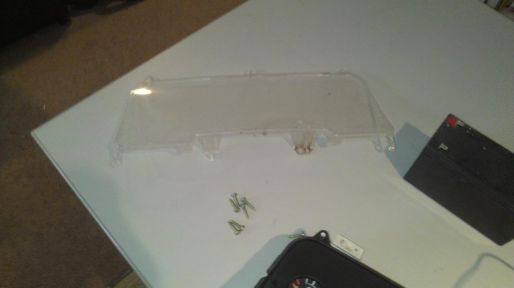
Step 1: Remove the clear cover. There should be 7 gold coloured screws on the outside. Be careful not to strip them. Once those are removed, gently lift it off, straight up.
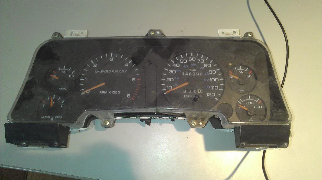
Here is what it will look like with the cover removed:
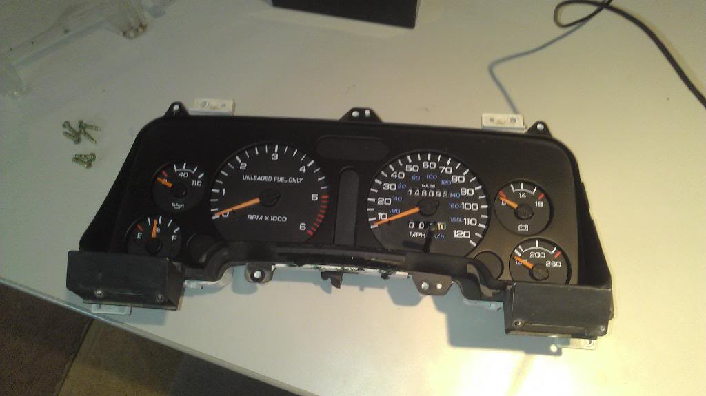
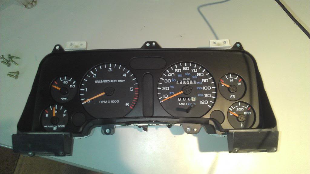
Here are the screws and the plastic cover:
Step 2:
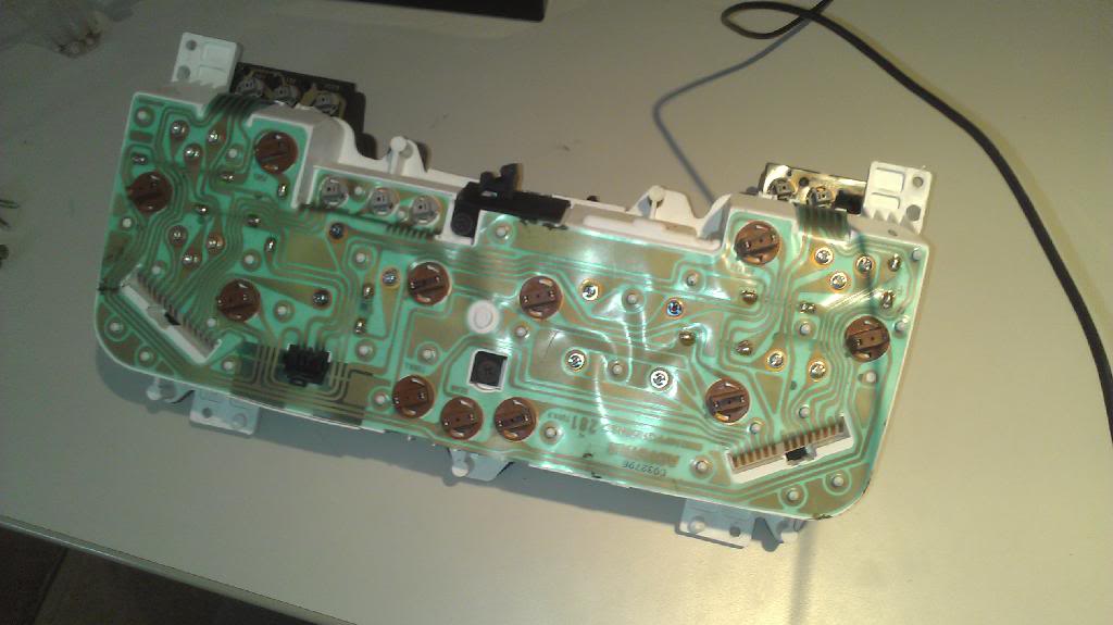
Flip the cluster over now. Make sure that the black plastic on the front stays on! It is still connected but is loose! See those little brown things? Those are the light bulb fixtures. Twist them counterclockwise and pull out to remove. Do this by hand, there should be no need for pliers. Remove ONLY the brown ones at this step. There will be 11 of these. Set them on their own pile. They all have the same bulbs, so no need to worry about mixing them up.
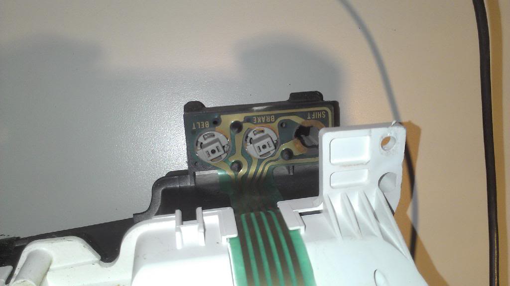
Next, you will go to the the right edge of the cluster (as it sits in the picture). Once again, these are light bulb fixtures. Rotate them counterclockwise. These tend to be tougher than the brown ones. You might need to use a pliers for these, PLEASE be very careful if you do that. I have only had to remove one of these with a pliers ever. There will be three on this side. Put them on their own pile. The bulbs are all the same here, so don't worry about mixing gray ones with gray ones. NOTE: Only Ram 1500 trucks with a manual transmission will have a bulb in the "SHIFT" socket. This is the "upshift" indicator bulb. If you don't have a bulb in there, there is no need to put one in (unless, of course, you know that you have the upshift indicator feature, you can get a new socket and bulb at NAPA, just take in one of the other gray ones to match it).
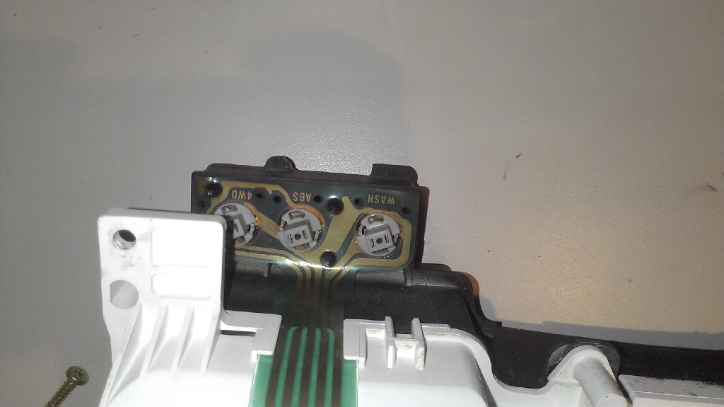
Next, go to the left edge of the cluster (as it sits in the picture). Do the same thing as you just did. As I noted above, all of the gray bulbs are the same, so put them on the same pile.
Step 3:
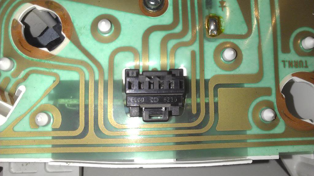
Next, find this black "jumper" connector on the instrument cluster. Pinch the tab inwards, and pull UP and out. It should come out without much difficulty. Set it aside by itself.
Next, go to the left corner again (as it sits in the picture). In the middle of the picture, notice that black "****" sticking up. This is slightly wider at the top than the bottom. This secures the PCB to the cluster. You will see these over the whole cluster. I will refer to these as "STUDS" throughout the rest of this article. BE SURE to follow the pattern I use to remove the PCB, otherwise you could tear, stretch, or otherwise damage the PCB!!!
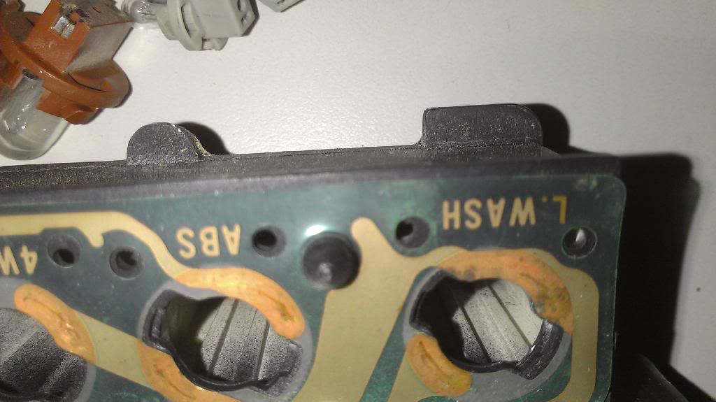
Start at the WASH corner, pick up the PCB between your fingers as shown, and pull it up. It will pop up and over the stud. There will be 2 studs on this section. Only remove these two. Do NOT jerk it up! The PCB is still connected elsewhere and if you jerk it up too far you could damage it! It won't take much effort to get it to pop off of the studs, so be GENTLE.
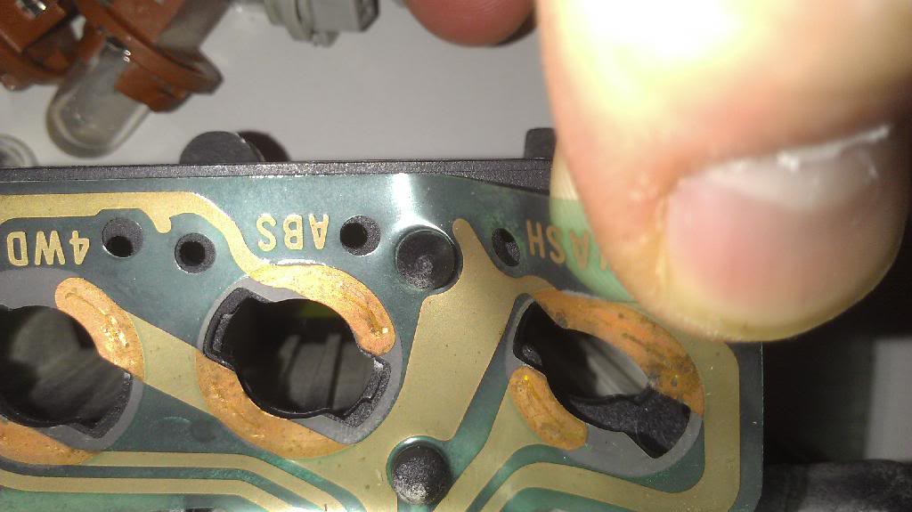
Now take a look at this:
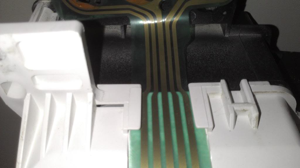
A closeup of it reveals that the PCB has a narrower section, enabling it to be slid into that slot. (sorry for the unclear picture, my camera wouldn't focus up that close, also it's upside down FYI, but you still should be able to see what I am talking about)
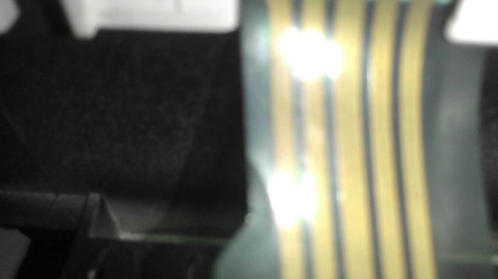
Now you can grab the part closer to the back of the cluster, and pull up until the slot aligns up right, then work the PCB out of the slot.
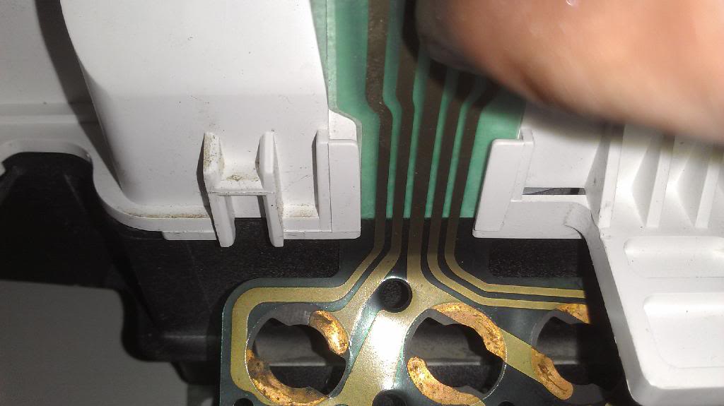
AND, it's out.
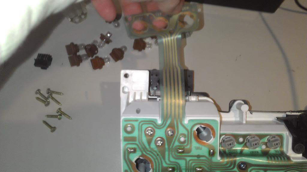
Do the same thing for the other side.
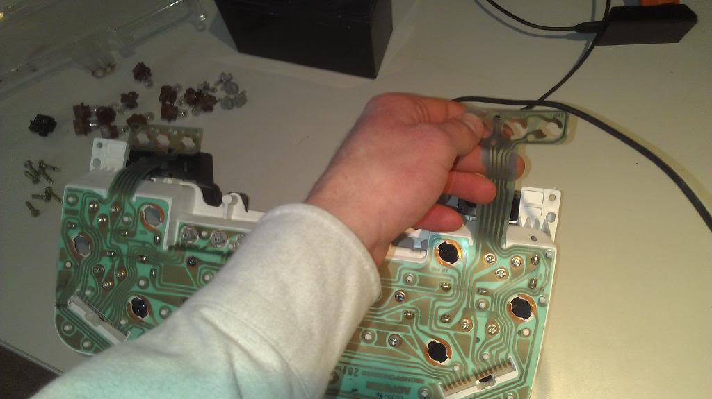
Step 4:
Now we can move to the next part. Look at this picture to notice the screws. There are quite a few of these, that is what connects the PCB to the gauges and also holds the gauges in.
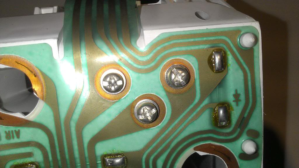
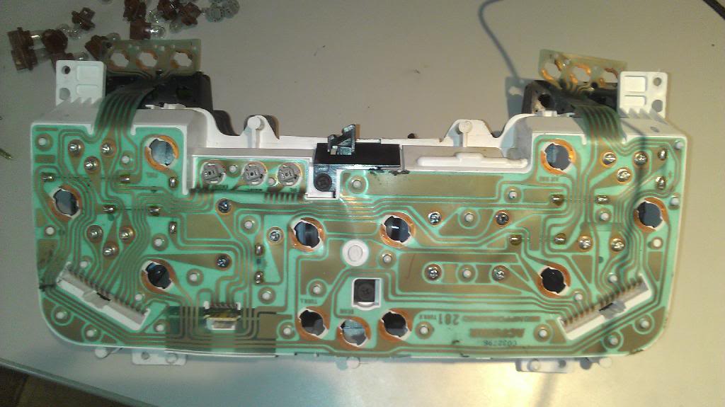
Now for a full view of the PCB. Look at all them screws!
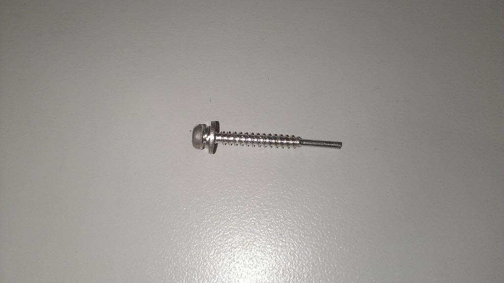
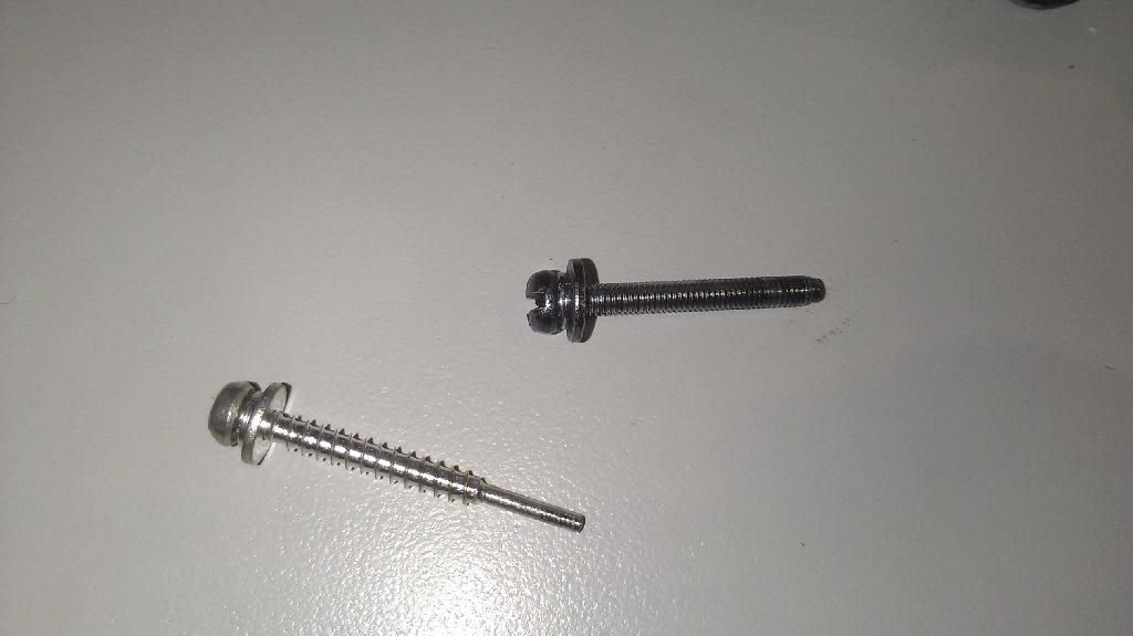
Here is a close-up of the most common type of screw. These conduct the signals from the PCB to the actual gauges. That's why they have that special tip.
Here, we start removing screws at the upper left corner of the instrument cluster (as it sits in the photos).
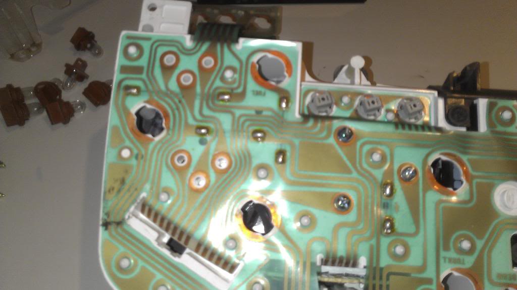
Now before you get too happy removing screws, you should know that there is more than one type of screw on the cluster! Keep them in separate piles. There is no need to worry about where they go on the cluster, they can only fit in their proper spots, so just put them on their appropriate piles.
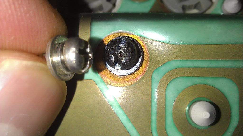
A comparison of the two types of screws we've seen so far on this cluster. What's the difference? This new type, which is coloured darker, as you can see, is the screw that holds the gauges in the cluster.
Last edited by aofarrell2; 03-07-2014 at 09:41 AM.
#6
Awesome.  Keep working on putting this together, and once finished, let me know, and I will move it to the DIY section. (although, I am pretty sure you can edit posts there.... don't wanna find out that you can't though.
  )
)
Any plans to do upgrades here?? (although, I am not entirely sure just what those would consist of...... )
 Keep working on putting this together, and once finished, let me know, and I will move it to the DIY section. (although, I am pretty sure you can edit posts there.... don't wanna find out that you can't though.
  )
)Any plans to do upgrades here?? (although, I am not entirely sure just what those would consist of...... )
#7
Awesome.  Keep working on putting this together, and once finished, let me know, and I will move it to the DIY section. (although, I am pretty sure you can edit posts there.... don't wanna find out that you can't though.
  )
)
Any plans to do upgrades here?? (although, I am not entirely sure just what those would consist of...... )
 Keep working on putting this together, and once finished, let me know, and I will move it to the DIY section. (although, I am pretty sure you can edit posts there.... don't wanna find out that you can't though.
  )
)Any plans to do upgrades here?? (although, I am not entirely sure just what those would consist of...... )
As far as upgrades/customization for people who are running the cluster as it would have been from the factory (with the computer), I will be showing how to re-skin the cluster, and make some other customizations to it as well. Possibly even how to get accurate readings from some of the gauges such as oil pressure etc.
Trending Topics
#8

