

DIY spyntec hub conversion
#1
 07-06-2010, 11:17 PM


DIY Spyntec Lockout Hub conversion
Have a copy of the spyntec install instructions handy, read it to the end. Use this instruction at your own risk, I am
not an expert and there may be alternate methods to use. this writeup is based on my experience with this kit.
Experts be kind... havent tackled hub work in a long long long... no longer time...
Tools needed
4 ton floor jack
6 ton jack stands (or equivelant)
large screwdriver
lug nut socket(s) various sizes.
4mm, 5mm allen sockets
13mm, 18mm 1 11/16" sockets
3/8 drvie inch lb torque wrench
1/2 drive ft lb torque wrench
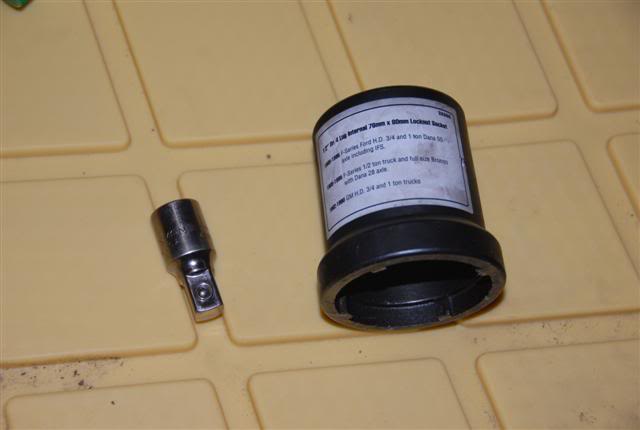
1/2 drive 4 lug internal 76mmx80mm locknut socket p/n25966 at autozone.
Materials needed
Royal Purple grease
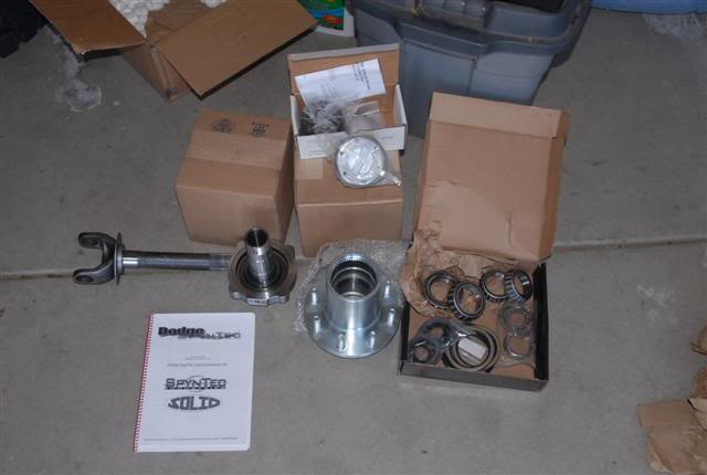
The kit
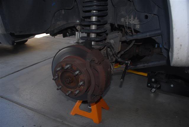
1) put axle on jackstands & remove both front wheels. make sure the axle is level, prevents fluid loss.
2) remove brake/abs line bracket from axle (13mm socket)
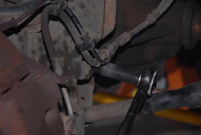
3) unclip abs wires from brake line so the caliper can be move out of the way
4) remove brake caliper (18mm socket) and place on the ground out of the way.
5) remove rotor
6) remove the abs sensor using the 5mm allen socket and move out of the way
7) using 1 11/16" socket & impact gun, remove cotter pin & axle nut
9) loosen the 4 hub bolts and back out approx 1/4" or so. (18mm socket)
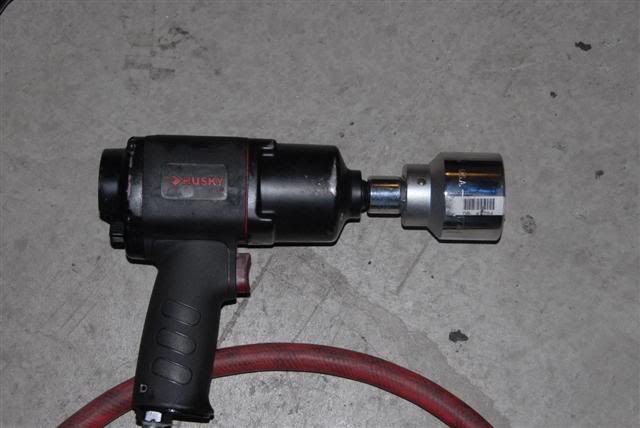
9) using 18mm and stubby extension, place socket up against the back of one of the hub bolts and turn
the steering wheel so that it pushes the socket up against the hub bolt... you may need to start the motor
and use the power steering to assist pushing the hub out. Gently push on the bolts with the steering,
move the socket to another bolt on the other side of the hub and repeat until hub breaks loose.
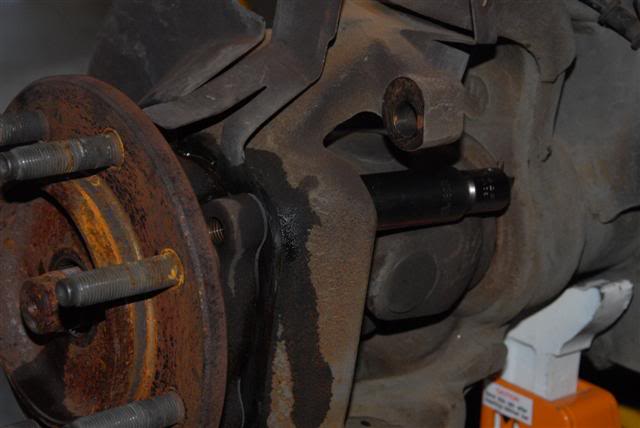
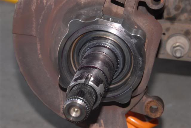
10) once the hub is loose, remove the bolts and slide the hub off the steering knuckle & axle
11) using screwdriver, pry out the axle enough so it starts to move out of the axle housing, once it is on its way out, you will want to support it on its way out. There is a seal on the inside of the axle you do not want to damage, so be aware. I pulled the axles out 3x so far and have not needed to change the seals... no leaks.
12) using 2 screwdrivers, pop out both retainer clips that hold the u-joint in place
13) using a large socket as a reciever place under one side of the u-joint and using a 2nd socket on top, tap the top socket to push the u-joint out on one side so that you can remove the cap, flip the axle over and tap the joint back into the 1st side so that the joint will move enough to come out, then tap out the other cap. (there may be an easier way)
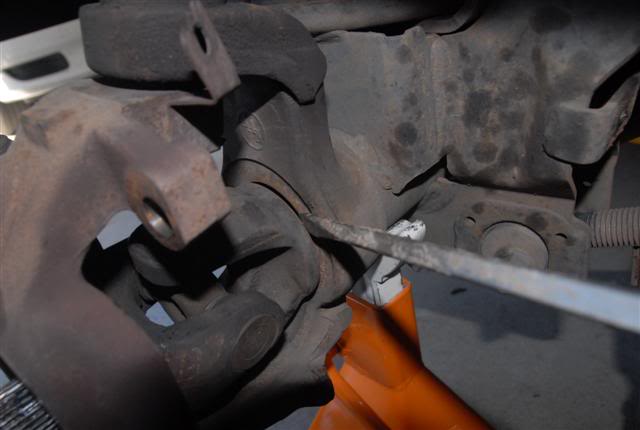
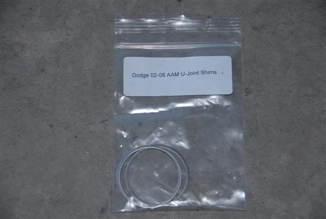
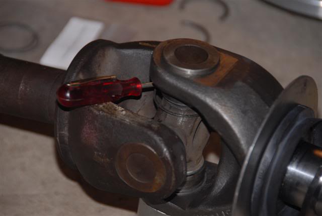
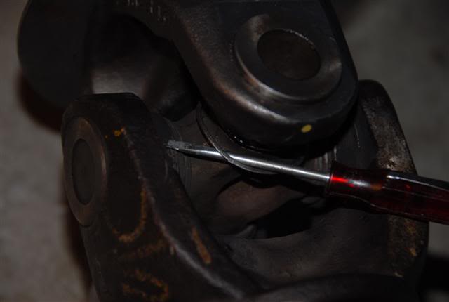
14) re-assemble using the new shaft and MAKE SURE YOU PUT THE SHIMS ON THE JOINT BEFORE YOU RE-ASSEMBLE... this was not in the instructions so I had to pull it appart and do a do-over. the screwdriver is there to allow you to see the shim. The shim goes between the clip & the yolk. replace the clips.
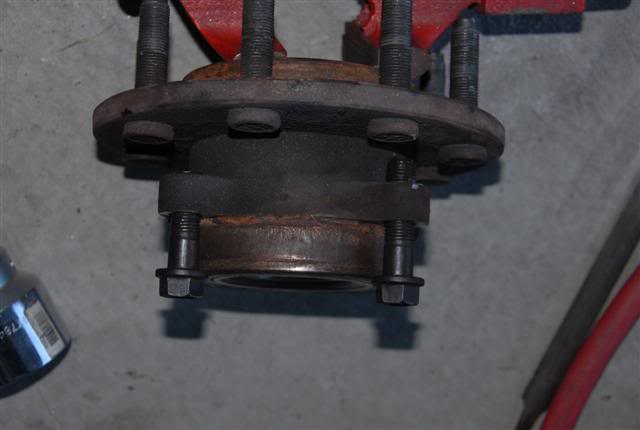
15) using a cut off wheel, shorten the hub bolts by about 3/8 of an inch. I found it easiest to cut the 1st bolt down after measuring it, then using the hub as a guide... made it pretty easy.
16) clean the steering knuckle surface using a wire brush
17) reinstall axle, put a light coating of grease on the end prior to installing & be careful of the seal when installing it. you may need to rotate it slightly to align the splines.
18) put anti-seize on the knuckle face & bore (per the instructions)
19) slide the seal that goes over the mud slinger so that the lip is towards the outside of the truck. this is the surface that will seal against the spindle. put a light coating of grease on this lip.
20) install the thrust washer over the stub shaft, instructions were not clear on which way it went so I put it with the flat surface facing outward. there is a beveled edge on one side, (experts please chime in here...)
19) install the dust shield between the knuckle & new spindle and using the cut hub bolts, bolt the spindle to the steering knuckle. Anti-seize is your best friend...
20) reinstall the ABS sensor using the 5mm allen socket, careful as they break easy over time. I had to use some force to wiggle it back into the sensor hole. You may need to bend the shield back into place. make sure there is enough clearance for the rotor.
21) install the v-lip seal over the hub & put a light coaging of grease on the v-lip.
22) pack the *&$^ out of the outer wheel bearing using your favorite method or tool. I tried a bearing packer tool but just made a mess and resorted to the old method of packing it using grease on the fingers and working it into the bearing. sorry, no pics... too messy.
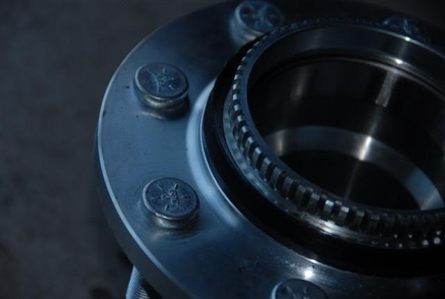
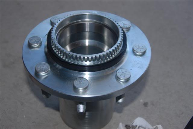
23) install the bearing into the back of the hub

24) using a hammer, tap in the rear seal into the hub

25) now pack the cr@p out of the rear bearing, seal with grease... clean the inside bearing surface with a clean rag, this surface will sit on the spindle and should not spin so grease here would not be good.
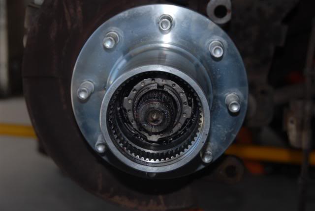
26) slide the hub onto the spindle.
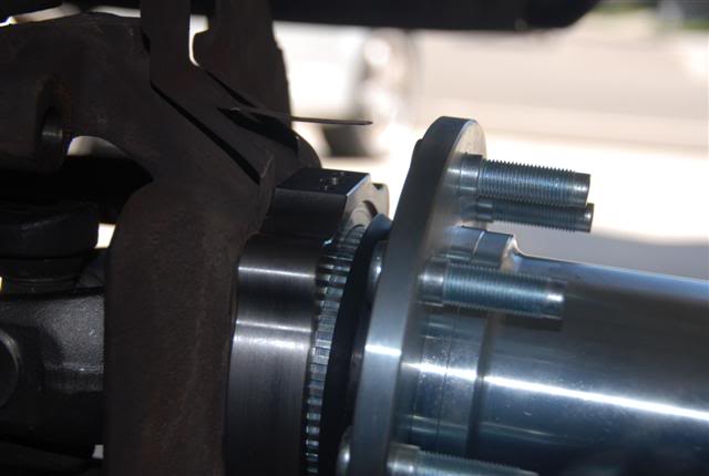
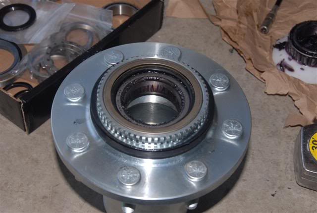
27) now pack the cr@p out of the front bearing and slide over the axle into the hub. Push it all the way up as far as you can, the hub should be centered on the axle.
part 2
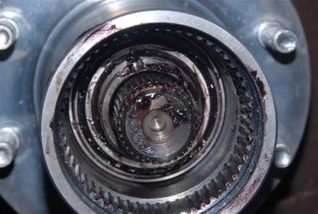
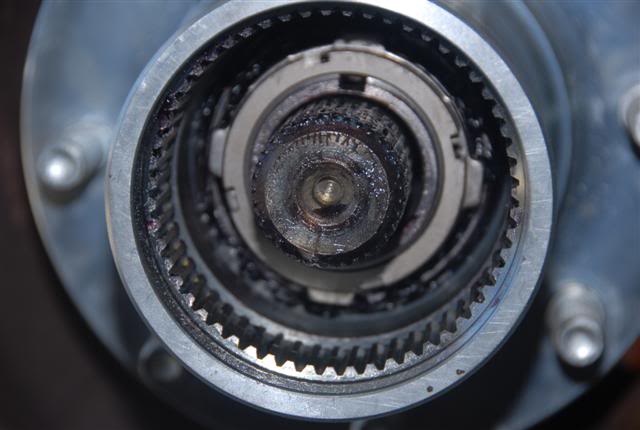
28) next your going to take the spindle nut that has the small pin sticking out of it and thread it onto the spindle. Note that the pin needs to face outward so that the locking ring can seat against it and this pin will go thru a hole in the lock ring.
29) Use the spindle nut socket to torque this spindle nut to 50 ft lbs. while you torque this nut down, rotate the hub back & forth & 360* around so that you seat the bearings. Once you have torqued this down, back the nut off up to 1/4 turn, enough so you can slide on the locking ring and find a hole for the pin to go thru. Once you have found this spot, grab the hub and push/pull to check for end play. there should be none. Instructions told me to back off 1/4 turn, then lock it down. Check for end play, if there is some, repeat. everytime I did this I had end play so I concluded they are wanting to remove the 50 ft lbs of torque and then lock it down. for me, this ended up being approx 1/8 turn or so. I did this for both sides, checked for end play (none) and rotated the hub to ensure bearings were not overly tight (they werent).
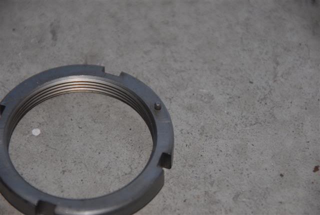
30) slide on the lock ring and adjust the spindle nut so that the pins goes thru one of the holes. NOW check for end play... if there is some you may need to repeat and flip the ring over... if you look at the placement of the holes, you have multiple spots where you can seat the spindle nut...
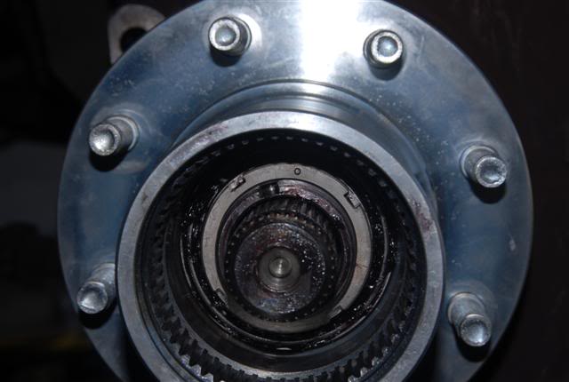
31) once the lock ring is in place, & there is no end play & the hub rotates freely as expected, place the lock nut over the spindle & tighten down to 125~150 ft lbs (per instructions)... I did 140
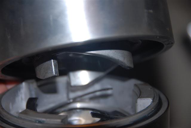
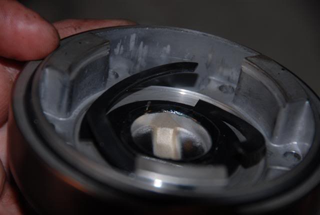
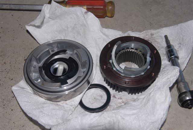
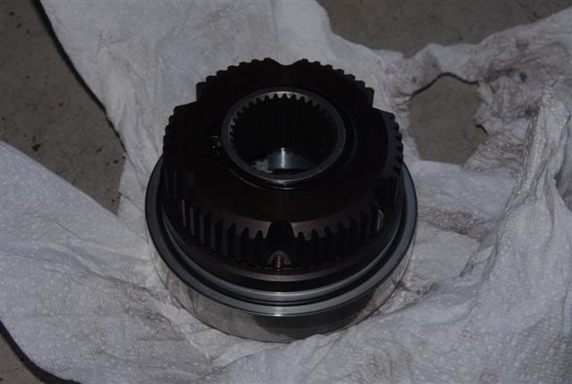
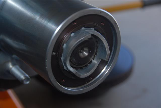
32) have a look at these 3 pictures... when you assemble the locker into the hub, it will only go 1 way. with the control in the "Free" position, the end of the spring needs to mate up to the bottom of the "tooth" such that when it is rotated to the "Lock" position, it does not slip off the end... if it does, it will not unlock and it will jam.
33) Next slide the lockout body into the hub, you may need to rotate it some to get it to line up.
34) insert the snap ring in the grove on the hub to hold the lockout body in place
35) there is an o-ring on the hub dial body, spread some grease over the o-ring to lubricate it.
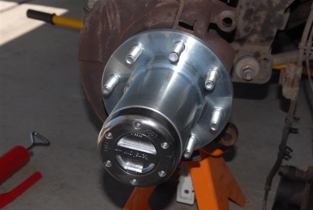
36) line up the dial with the lockout body and bolt down with the allen bolts supplied (4mm allen socket)
torque the bolts in a cross pattern to 30 inch lbs.
37) now rotate the assembly with the selector in the "Free" position and verify that the u-joint/axle does not spin.
38) rotate the selector to the "Lock" position & verify that the u-joint/axle now spins as expected.
39) rotate the selector back to "Free" and verify the hub unlocks from the axle... if it does, yippee skippee...
40) reinstall the rotor, if needed, spray both sides with brake cleaner
41) reinstall caliper
42) reinstall abs/brake line bracket to axle & clip all the abs wires back into the clips on the brake line.
43) reinstall wheel and have a beer.
44) repeat for the other side, once complete, take it for a spin with the selectors in the free position.
45) verify there is no bearing noise, drive it long enough to heat things up, pull over & feel both hubs. they should be warm to the touch and you should be able to hold your hand on it for a few seconds. If both sides feel the same & there is no noise, lock the hubs & repeat.
46) verify that both hubs can be unlocked as expected.
47) if all testing is good... then your done.
Hope this helps... remember I'm not a mechanic (test engineer) but I like to pretend to be hahaha...
Have a copy of the spyntec install instructions handy, read it to the end. Use this instruction at your own risk, I am
not an expert and there may be alternate methods to use. this writeup is based on my experience with this kit.
Experts be kind... havent tackled hub work in a long long long... no longer time...
Tools needed
4 ton floor jack
6 ton jack stands (or equivelant)
large screwdriver
lug nut socket(s) various sizes.
4mm, 5mm allen sockets
13mm, 18mm 1 11/16" sockets
3/8 drvie inch lb torque wrench
1/2 drive ft lb torque wrench
1/2 drive 4 lug internal 76mmx80mm locknut socket p/n25966 at autozone.
Materials needed
Royal Purple grease
The kit
1) put axle on jackstands & remove both front wheels. make sure the axle is level, prevents fluid loss.
2) remove brake/abs line bracket from axle (13mm socket)
3) unclip abs wires from brake line so the caliper can be move out of the way
4) remove brake caliper (18mm socket) and place on the ground out of the way.
5) remove rotor
6) remove the abs sensor using the 5mm allen socket and move out of the way
7) using 1 11/16" socket & impact gun, remove cotter pin & axle nut
9) loosen the 4 hub bolts and back out approx 1/4" or so. (18mm socket)
9) using 18mm and stubby extension, place socket up against the back of one of the hub bolts and turn
the steering wheel so that it pushes the socket up against the hub bolt... you may need to start the motor
and use the power steering to assist pushing the hub out. Gently push on the bolts with the steering,
move the socket to another bolt on the other side of the hub and repeat until hub breaks loose.
10) once the hub is loose, remove the bolts and slide the hub off the steering knuckle & axle
11) using screwdriver, pry out the axle enough so it starts to move out of the axle housing, once it is on its way out, you will want to support it on its way out. There is a seal on the inside of the axle you do not want to damage, so be aware. I pulled the axles out 3x so far and have not needed to change the seals... no leaks.
12) using 2 screwdrivers, pop out both retainer clips that hold the u-joint in place
13) using a large socket as a reciever place under one side of the u-joint and using a 2nd socket on top, tap the top socket to push the u-joint out on one side so that you can remove the cap, flip the axle over and tap the joint back into the 1st side so that the joint will move enough to come out, then tap out the other cap. (there may be an easier way)
14) re-assemble using the new shaft and MAKE SURE YOU PUT THE SHIMS ON THE JOINT BEFORE YOU RE-ASSEMBLE... this was not in the instructions so I had to pull it appart and do a do-over. the screwdriver is there to allow you to see the shim. The shim goes between the clip & the yolk. replace the clips.
15) using a cut off wheel, shorten the hub bolts by about 3/8 of an inch. I found it easiest to cut the 1st bolt down after measuring it, then using the hub as a guide... made it pretty easy.
16) clean the steering knuckle surface using a wire brush
17) reinstall axle, put a light coating of grease on the end prior to installing & be careful of the seal when installing it. you may need to rotate it slightly to align the splines.
18) put anti-seize on the knuckle face & bore (per the instructions)
19) slide the seal that goes over the mud slinger so that the lip is towards the outside of the truck. this is the surface that will seal against the spindle. put a light coating of grease on this lip.
20) install the thrust washer over the stub shaft, instructions were not clear on which way it went so I put it with the flat surface facing outward. there is a beveled edge on one side, (experts please chime in here...)
19) install the dust shield between the knuckle & new spindle and using the cut hub bolts, bolt the spindle to the steering knuckle. Anti-seize is your best friend...
20) reinstall the ABS sensor using the 5mm allen socket, careful as they break easy over time. I had to use some force to wiggle it back into the sensor hole. You may need to bend the shield back into place. make sure there is enough clearance for the rotor.
21) install the v-lip seal over the hub & put a light coaging of grease on the v-lip.
22) pack the *&$^ out of the outer wheel bearing using your favorite method or tool. I tried a bearing packer tool but just made a mess and resorted to the old method of packing it using grease on the fingers and working it into the bearing. sorry, no pics... too messy.
23) install the bearing into the back of the hub
24) using a hammer, tap in the rear seal into the hub
25) now pack the cr@p out of the rear bearing, seal with grease... clean the inside bearing surface with a clean rag, this surface will sit on the spindle and should not spin so grease here would not be good.
26) slide the hub onto the spindle.
27) now pack the cr@p out of the front bearing and slide over the axle into the hub. Push it all the way up as far as you can, the hub should be centered on the axle.
part 2
28) next your going to take the spindle nut that has the small pin sticking out of it and thread it onto the spindle. Note that the pin needs to face outward so that the locking ring can seat against it and this pin will go thru a hole in the lock ring.
29) Use the spindle nut socket to torque this spindle nut to 50 ft lbs. while you torque this nut down, rotate the hub back & forth & 360* around so that you seat the bearings. Once you have torqued this down, back the nut off up to 1/4 turn, enough so you can slide on the locking ring and find a hole for the pin to go thru. Once you have found this spot, grab the hub and push/pull to check for end play. there should be none. Instructions told me to back off 1/4 turn, then lock it down. Check for end play, if there is some, repeat. everytime I did this I had end play so I concluded they are wanting to remove the 50 ft lbs of torque and then lock it down. for me, this ended up being approx 1/8 turn or so. I did this for both sides, checked for end play (none) and rotated the hub to ensure bearings were not overly tight (they werent).
30) slide on the lock ring and adjust the spindle nut so that the pins goes thru one of the holes. NOW check for end play... if there is some you may need to repeat and flip the ring over... if you look at the placement of the holes, you have multiple spots where you can seat the spindle nut...
31) once the lock ring is in place, & there is no end play & the hub rotates freely as expected, place the lock nut over the spindle & tighten down to 125~150 ft lbs (per instructions)... I did 140
32) have a look at these 3 pictures... when you assemble the locker into the hub, it will only go 1 way. with the control in the "Free" position, the end of the spring needs to mate up to the bottom of the "tooth" such that when it is rotated to the "Lock" position, it does not slip off the end... if it does, it will not unlock and it will jam.
33) Next slide the lockout body into the hub, you may need to rotate it some to get it to line up.
34) insert the snap ring in the grove on the hub to hold the lockout body in place
35) there is an o-ring on the hub dial body, spread some grease over the o-ring to lubricate it.
36) line up the dial with the lockout body and bolt down with the allen bolts supplied (4mm allen socket)
torque the bolts in a cross pattern to 30 inch lbs.
37) now rotate the assembly with the selector in the "Free" position and verify that the u-joint/axle does not spin.
38) rotate the selector to the "Lock" position & verify that the u-joint/axle now spins as expected.
39) rotate the selector back to "Free" and verify the hub unlocks from the axle... if it does, yippee skippee...
40) reinstall the rotor, if needed, spray both sides with brake cleaner
41) reinstall caliper
42) reinstall abs/brake line bracket to axle & clip all the abs wires back into the clips on the brake line.
43) reinstall wheel and have a beer.
44) repeat for the other side, once complete, take it for a spin with the selectors in the free position.
45) verify there is no bearing noise, drive it long enough to heat things up, pull over & feel both hubs. they should be warm to the touch and you should be able to hold your hand on it for a few seconds. If both sides feel the same & there is no noise, lock the hubs & repeat.
46) verify that both hubs can be unlocked as expected.
47) if all testing is good... then your done.
Hope this helps... remember I'm not a mechanic (test engineer) but I like to pretend to be hahaha...
#2
07-07-2010, 03:35 PM
Record Breaker
#3
07-07-2010, 03:51 PM
thanks...
hub socket was $20, grease was $22 (royal purple @ $11 ea, took only 1 though) the kit... $1595 shipped... all the other tools I had.
Also, since it will be asked... I measured 1.8~1.9 mpg on a 120 mi test loop before & after. I think that may be kinda misleading though as I had 20~30 mph winds on ea trip. I have consistently seen 50/50 city/hiway mpg above 17, previously I'd be expecting 14.5~15.5. Hiway has all been above 18 mpg easily. If I keep my foot out of it and drive for mileage... 20~20.5 mpg.
the biggest plus to this kit is the city mpg bump... you can coast so much farther without the added drag of the other parts. drive smart & you should see a 2.0 mpg bump in the city.
quite happy...