

DIY: 2ND Gen Ram Ground-up Re-Wire


Thread Starter
|
Champion
Joined: Jun 2012
Posts: 3,096
Likes: 2
From: Iowa
Quite often it comes up that the factory wiring is inadequate, or doesn't have the extra stuff that people want, or is not suitable for engine/transmission swaps.
Personally since I swapped to a manual transmission and a carb'd engine, I do not need all the extra computer junk. And I swapped for the quad-beam (Sport-style) headlamps, and found the factory harness was inadequate even to run the factory headlamps (how many times have I had to replace the headlight switch??). as well my chassis harness is failing in various spots - opening the harness reveals that wires have rubbed and chafed or even melted (yikes!) so I decided to rip out all of that factory wiring and re-do it from the ground up with high-quality components and properly setup. After looking around at "universal" wiring kits (99% of the "universal" ones were made for GM - all GM connectors and switches - they just sent extra wire in hopes that you would need it! - and if not GM they were just cheap skimpy harnesses - not what I wanted), I decided to make my own from scratch.
I had a thread in the DIY section previously - it only addressed the quad-beam headlamps - and since I decided to re-do ALL the wiring, I asked a mod to delete it so I could start a new one (this one). All of my diagrams are ENTIRELY new. Over the next few weeks I will continue to upload the diagrams one by one as I make them. Then, as I do the actual making of the harnesses I will post pictures and step by step.
If you are wanting to cheap out, don't bother with your electrical system!! Use only the best. I have spent a lot of time researching and trying out components - you don't have to. Also remember - more expensive isn't always better. It is the quality that counts. Also note: A very large amount of vehicle fires are due to the electrical system!!! That is why I have carefully sized all wires, fuses, and other electrical components and have been very selective about what components I use! Don't try to substitute or get away without using the right tools - they DO make a difference and can be what makes or breaks your new harness. In other words, you can't make a quality harness without using the right tools, every time, the right way. They are just as important as quality components.
I am not responsible for any damage to your vehicle, incidentially or consequentially, indirectly or directly, related to following these instructions! While I have taken the time to ensure that these instructions are competent, I take ABSOLUTELY no liability, and give absolutely no warranty, implied or expressly stated.
For the basics:
- I use GPT insulated USA MADE wire. Please note - most of the automotive wire available in the auto parts stores and much of the online stuff claims to be copper - IT ISN'T! It has small amounts of aluminum mixed in. This GPT wire I use is PURE COPPER, made in the USA. There is NOT A TRACE of aluminum in it. This makes for the best conductor. Adding aluminum only reduces cost and only slightly increases flexibility - you won't need the addded flexibility in a truck application. Once you are done wiring you won't need to flex the wire - so who cares. You probably won't notice the difference anyways. Many places use TXL or SGL/SGT wire - claiming it is a higher grade than GPT. The difference - GPT insulation loses a lot of flexibility at negative 40 degrees Fahrenheit - TXL and SGL/SGT wire loses flexibility at negative fifty degrees Fahrenheit. You won't be out trying to modify wire in -40* weather anyway, would you? Chances are nil. GPT wire is oil, gasoline, and chemical resistant, and is waterproof. It is also approved for marine applications (when the wire is tinned). Also, GPT can't handle quite as high of temperatures as TXL or SGL/SGT wire, but if you are careful to shield the wire, where you route it, and how well you put the plastic looming on it, it will be properly protected from heat and will perform just fine.
- You will need a heat gun. Flame is NOT permissible - even if you manage not to catch the insulation on fire - it still can cause the insulation to deteriorate, which is an absolute no-no. Use a heat gun instead - and use it carefully. You don't want to use too much heat and you want to apply heat as uniformly as possible.
- Use ONLY silicon di-electric grease for protecting terminals. This does not apply to battery terminals. Use it sparingly, and be sure to seal the terminal appropriately - a sealed cover or electrical tape.
- For electrical tape, I use a high-grade 3M tape. It is very flexible even when cold, and has a superior adhesive. Don't use the cheaper stuff - it will get brittle and WILL NOT LAST! This tape is pretty expensive - last I knew it was $25 per roll - but is well worth the extra cost to get the best. This is the stuff that you will come to 10 years down the road - and find it still adhered well and still plenty flexible. The other stuff won't.
- Always leave extra length on the wire - you will be glad you did! You can't leave too much extra - but you CAN have too little. Either because of a measuring error, or you make a mistake and have to cut off some wire (splice didn't work right, etc.)
If you have any suggestions, or notice any errors, let me know and I'll be happy to fix them. If I include your suggestions I will be sure to give you credit (if I forget - remind me).
All diagrams and instructions belong to me. You are free to use them, modify, or print them off for personal use only. You may not resell them or distribute them (exception: printing them off for a friend - but no charging for the diagrams and instructions themselves!). If you quote these instructions, in part or whole - link to this thread! Otherwise I will ask to have your post deleted. I have spent many long hours in front of a computer screen and outside to provide you with this - free of charge - and I think it is plenty reasonable to ask for proper credit. Also, using these instructions and diagrams to make a harness or other things to re-sell (not as part of a vehicle - if you made a harness and put it in your vehicle and sold it as part of the vehicle - that's fine) is not permitted. Why the long statement? Quite simply, I've had other things I've put many hours into stolen - and I'm not gonna let that happen again. 99% of people never would have needed this statement - but for those few that do, it's out here.
Have any suggestions (maybe change that slightly, this feature should be standard?), additions (an extra circuit for some fancy gizmo?), or modifications (I would do it this way because X...)? Let me know - I'll review them, and if I deem them safe I will add them and give you credit for it!
Please note - this thread is currently open to discussion - but when it gets moved - be aware that your posts may be deleted so as to clean it up. Any suggestions etc. will be merged into my posts.
Thread Starter
|
Champion
Joined: Jun 2012
Posts: 3,096
Likes: 2
From: Iowa
I will be providing a PDF file with a cross-reference of notations and part ID's, as well as tech specs/troubleshooting and theory explanation (as necessary).
First off, many people re-wiring their trucks will be using the quad-beam headlights. Whether they are aftermarket or the OEM Sport style, I assume that they have four light bulbs. I have oversized the wires a bit to allow for the use of more powerful bulbs. I will publish max loads in the technical document - so you can know the limits of the system.
I have sources for many factory connectors BRAND NEW - so that we can start fresh without having to worry about brittle connectors. In the case of a connector I can't get, I will explain how to "re-pin" a connector.
I have a bunch of extra wiring in here that some people may elect to remove - so I have split up the wiring diagrams so that you can. For example, some people may not want cab clearance lights or running lights - so I keep that separate. I also make provision in the standard circuits so that you can add the auxiliary circuits should you want to later without much difficulty.
Also note: The only computer that remains, per federal law, is the Airbag system. I take no responsibility if it doesn't deploy when it should have. As above I provide no guarantee that the wiring for it will work - hook one wire up wrong, and you could blow up your airbag - not my fault!
I also try to remain somewhat "modular" - i.e. the engine wiring is setup so that you can use either a diesel "sub-harness" or a gasoline "sub-harness" - depending on what engine you choose for a swap. This harness does NOT cover fuel injection - at least not yet. I may consider doing one for a MegaSquirt setup - if it is wanted.
Reference
How to identify a circuit
Wires have a label - in green with a red dot on the wire - on the diagrams.
An example label:
Circuit C1 10/GN
This is read as the following:
C1: Circuit ID 1. Cross this on the Circuit ID reference table (the table isn't finished yet - I will just write them out for now)
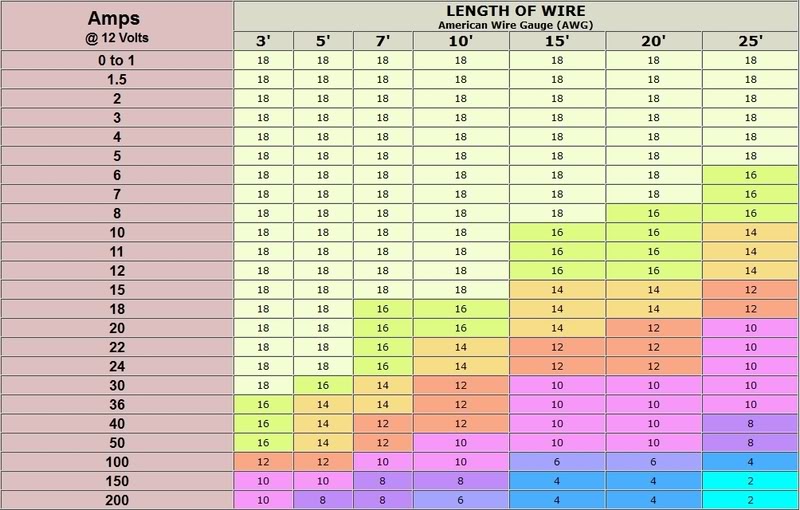
10/: 10 gauge wire. Follow the AWG standard. Smallest gauge of wire used in this project is 18. Largest used in this project is 2/0 (IIRC).
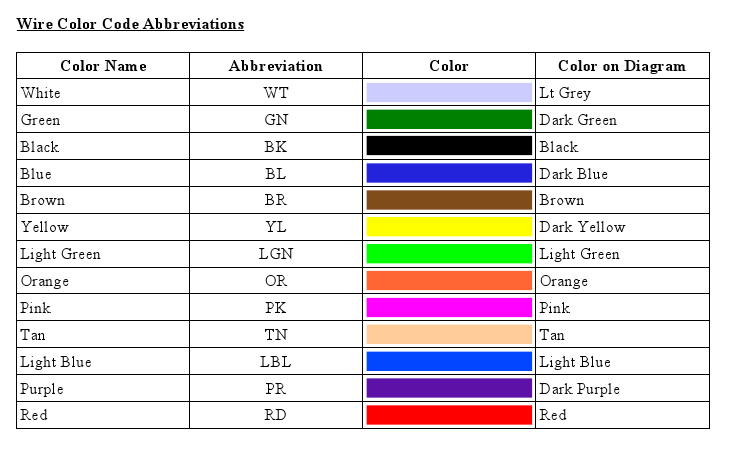
GN: Color code. Reference to color code chart. Wires are colored as well on the diagram to make it easier. A dash followed by another color code means that the color code following the dash is the secondary color, i.e. that is the color of the stripe on the wire.
Circuit ID Reference
C1: Headlamps
C2: Fog lamps
C3: Front turn signals
C4:
C5:
C6:
C7:
Wire Load Rating and Length Reference
Wire Color Codes
First off, many people re-wiring their trucks will be using the quad-beam headlights. Whether they are aftermarket or the OEM Sport style, I assume that they have four light bulbs. I have oversized the wires a bit to allow for the use of more powerful bulbs. I will publish max loads in the technical document - so you can know the limits of the system.
I have sources for many factory connectors BRAND NEW - so that we can start fresh without having to worry about brittle connectors. In the case of a connector I can't get, I will explain how to "re-pin" a connector.
I have a bunch of extra wiring in here that some people may elect to remove - so I have split up the wiring diagrams so that you can. For example, some people may not want cab clearance lights or running lights - so I keep that separate. I also make provision in the standard circuits so that you can add the auxiliary circuits should you want to later without much difficulty.
Also note: The only computer that remains, per federal law, is the Airbag system. I take no responsibility if it doesn't deploy when it should have. As above I provide no guarantee that the wiring for it will work - hook one wire up wrong, and you could blow up your airbag - not my fault!
I also try to remain somewhat "modular" - i.e. the engine wiring is setup so that you can use either a diesel "sub-harness" or a gasoline "sub-harness" - depending on what engine you choose for a swap. This harness does NOT cover fuel injection - at least not yet. I may consider doing one for a MegaSquirt setup - if it is wanted.
Reference
How to identify a circuit
Wires have a label - in green with a red dot on the wire - on the diagrams.
An example label:
Circuit C1 10/GN
This is read as the following:
C1: Circuit ID 1. Cross this on the Circuit ID reference table (the table isn't finished yet - I will just write them out for now)
10/: 10 gauge wire. Follow the AWG standard. Smallest gauge of wire used in this project is 18. Largest used in this project is 2/0 (IIRC).
GN: Color code. Reference to color code chart. Wires are colored as well on the diagram to make it easier. A dash followed by another color code means that the color code following the dash is the secondary color, i.e. that is the color of the stripe on the wire.
Circuit ID Reference
C1: Headlamps
C2: Fog lamps
C3: Front turn signals
C4:
C5:
C6:
C7:
Wire Load Rating and Length Reference
Wire Color Codes

Last edited by aofarrell2; May 13, 2014 at 02:11 PM.
Thread Starter
|
Champion
Joined: Jun 2012
Posts: 3,096
Likes: 2
From: Iowa
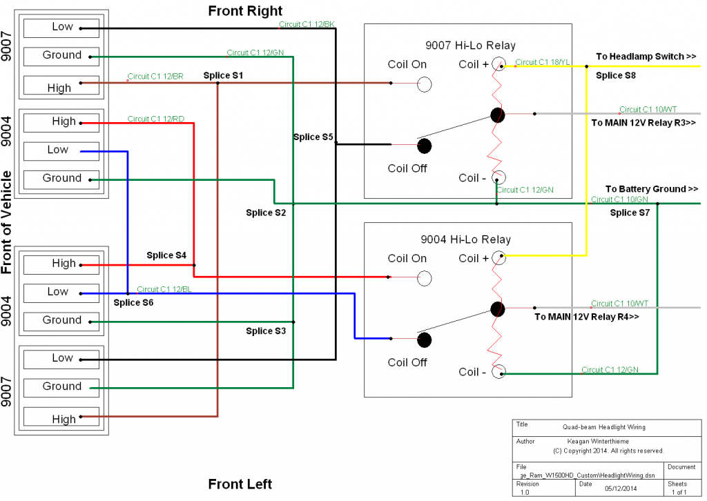
The first diagram up is the quad-beam headlight setup.
The circuit is divided based upon the bulb, i.e. the 9007 circuit (outside bulb on both sides) or 9004 circuit (inside bulb on both sides).
Theory:
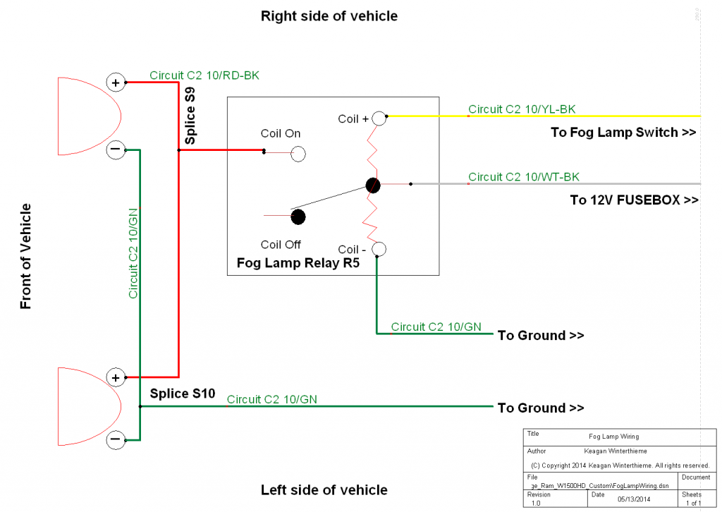
When the operator turns on the headlamps, the headlamp switch sends power to the Multi-Function switch (for the high/low beam selection signal), and also send a signal to the MAIN 12V Relays (Relays R3 and R4) to send power to the HIGH/LOW selection relays (Relays R1 and R2) MAIN 12V terminal. The multi-function switch selects either high or low beam operation based on operator selection. If the operator selects HIGH, it sends a signal to relays R1 and R2, and also sends a signal to the instrument cluster (high-beam indicator). If the operator selects LOW, it does not send a signal to relays R1 and R2 (relays R1 and R2 assume low-beam if no signal - so if the multi-function switch fails, it will default to low beam - this ensures that you have lights in case it should fail!). Instead it sends a signal to the Fog Lamp Switch, which, if the operator has enabled fog lamp operation, it will send the signal to relay R5 (Fog Lamp Relay) to engage the fog lamps (factory setup only allows fog lights to operate with low beam, per regulation - I DO NOT encourage you to modify it to allow fog lamps regardless of beam selection).
All diagrams will be available in a ZIP file, which will include the technical document, when I have completed the whole project and it is in the vehicle and working entirely.
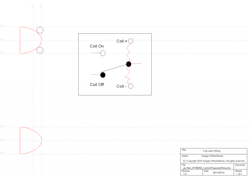
Here's the first diagram (please note - the diagrams might not always display correctly when shrunk - click on the image and it should fix it).
Fog Lamp Wiring:
The circuit is divided based upon the bulb, i.e. the 9007 circuit (outside bulb on both sides) or 9004 circuit (inside bulb on both sides).
Theory:
When the operator turns on the headlamps, the headlamp switch sends power to the Multi-Function switch (for the high/low beam selection signal), and also send a signal to the MAIN 12V Relays (Relays R3 and R4) to send power to the HIGH/LOW selection relays (Relays R1 and R2) MAIN 12V terminal. The multi-function switch selects either high or low beam operation based on operator selection. If the operator selects HIGH, it sends a signal to relays R1 and R2, and also sends a signal to the instrument cluster (high-beam indicator). If the operator selects LOW, it does not send a signal to relays R1 and R2 (relays R1 and R2 assume low-beam if no signal - so if the multi-function switch fails, it will default to low beam - this ensures that you have lights in case it should fail!). Instead it sends a signal to the Fog Lamp Switch, which, if the operator has enabled fog lamp operation, it will send the signal to relay R5 (Fog Lamp Relay) to engage the fog lamps (factory setup only allows fog lights to operate with low beam, per regulation - I DO NOT encourage you to modify it to allow fog lamps regardless of beam selection).
All diagrams will be available in a ZIP file, which will include the technical document, when I have completed the whole project and it is in the vehicle and working entirely.
Here's the first diagram (please note - the diagrams might not always display correctly when shrunk - click on the image and it should fix it).

Fog Lamp Wiring:

Last edited by aofarrell2; May 13, 2014 at 02:28 PM.
Thread Starter
|
Champion
Joined: Jun 2012
Posts: 3,096
Likes: 2
From: Iowa
For the curious. How can I line everything up?
In my CAD program there is a tool called Rulers. They snap into place - when I'm done with them I simply select them and hit the DEL key. Please note: You might not be able to see the lines right away - if that is the case, adjust the contrast on your monitor. I can see it just fine on mine without adjusting the contrast. Or look at them from a different angle - they are grey dotted lines.
In my CAD program there is a tool called Rulers. They snap into place - when I'm done with them I simply select them and hit the DEL key. Please note: You might not be able to see the lines right away - if that is the case, adjust the contrast on your monitor. I can see it just fine on mine without adjusting the contrast. Or look at them from a different angle - they are grey dotted lines.
