


remote start 2006 mega cab fortin evo-chr and ultra start 3290


Thread Starter
|
Registered User
Joined: Aug 2011
Posts: 1
Likes: 0
Hi all, decided to install a 2-way remote start in my 2006 1500 Mega Cab. Rather than go with a OEM crap starter, I went with a nice 2-way ultrastart with up to a .5 mile range. To make it easier as I have never installed a remote start, I paired the ultra start 3290LED (http://stores.ebay.com/discountcarst...id=p4340.l2563) with the fortin evo-chr with the harness for a 2006 model THAR-CHR2 (http://www.amazon.com/gp/product/B002NMXO4W). For the 06 model you'll also need a SPDT 30 Amp 5 pin relay: (http://www.amazon.com/Absolute-RLS12...d_bxgy_e_img_b)
This setup will run you about $130 which is pretty good in my opinion.
Tools you'll need:
1. T15 torx driver - luckily I had a torx driver at this size because my driver that allows you to put multiple bits in was too wide for one of the bolts on the steering column shroud.
2. Wire Strippers
3. Philips head driver
4. Female spade connectors
5. About 5-10' of power wire (I think mine was 14 awg)
6. Soldering iron or something to connect wires securely
7. Zip Ties to manage the rats nest of wires you'll end up with
Steps:
1. Take apart the steering column shroud. This is connected with a couple T-15 bolts. You may have to unscrew the steering wheel column lever as well.
2. Pull off the front panel which is attached by two screws underneath and pull out. It will pop off.
3. Unscrew the metal panel underneath the panel which is attached by 4 screws. Note the tabs after you pull the panel off that determine how the panel will be put back on.
4. Attach the t-harness as indicated by the fortin instructions. This is a picture of the harness you'll pull from the ignition column on the right side:
5. Cut and strip back 4 of the 5 wires in the 5 pin ignition column on the LEFT side. Make sure you give yourself enough space to cut the wires and strip them making connections. I cut the wires about 4 inches back of the harness: . The blue wire is the 12v+ wire. The green/yellow wire is the starter 1+ wire. The pink/white wire is the Ignition 1+ wire. The purple/black wire is the MUX AC/Data wire. DO NOT cut the bottom purple wire which is the MUX ground wire.
6. Start connecting the wires. The order doesn't matter but here is how it goes:
* Ultra Start (US) yellow starter output wire -> Lt. Blue/Black Evo-chr -> green/yellow starter wire on truck.
* Blue US ignition 1 output -> yellow wire evo-chr
* white US ignition 2 output -> pink/white ignition wire on truck
* power wire from battery -> red wires on US. I pushed the power wire through that rubber grommet against the firewall.
* black ground wire US -> a grounding connection on the truck. There is one on the right hand side that was easy to unbolt and use.
* blue/white US tach input wire -> pink wire on evo-chr (US can't use the tach input from datalink connecton on the evo-chr)
* white/violet while running output US -> pin 85 on relay
* blue truck wire -> pin 86 on relay
* white/black mux wire on evo-chr -> pin 87 relay
* Mux relay connections, this was the only confusing part for me looking at the fortin diagram. Basically when you cut the wire, one side will go to pin 87a, and the other side to 30 thus making a relay.
a. purple/black mux ac/data wire on truck -> pin 87a relay
b. purple/black mux ac/data wire on truck -> pin 30 relay
7. Connect all harnesses to evo-chr and US except the 8 pin t-harness of the evo-chr that comes from the steering column as outlined in the manual.
8. Follow fortin evo-chr instructions on programming the bypass module.
9. Once programmed, the ultra start should work. Test this before you start figuring out where you are going to place the rats nest of wires and soldering connections. There is what all these connections looked like afterwards before I started soldering: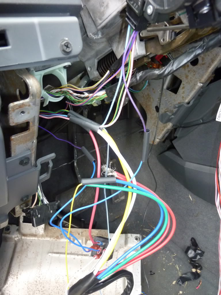 .
.
10. Once remote start is working, figure out some attachment points where you can place the US and evo-chr. There are some good spots underneath and to the left.
Also to note, I didn't install parking light wire to the US. It doesn't do much other than help diagnosis things in my opinion. If you do want to hook it up, it is the white/grey wire located in the kick panel. There is a bolt that you can unscrew that allows you to pull out the huge wire harness in the kick panel. If you pop off the plastic cover on this harness, it will give you some more room to work with. I have a multi-meter so I simply connected my multi-meter to the US parking light wire (white wire) to diagnosis things. The US will also make a noticeable click sound when it sends output to this wire.
Good luck, it took me about 4 hours to do this only because it takes some time to connect all the wires and validate they all work before you end up soldering them. So in essence, I had to do everything twice. I would say on a scale of 1-10 of being difficult, this was a 3.
Hope this helps, good luck
-Kevin
This setup will run you about $130 which is pretty good in my opinion.
Tools you'll need:
1. T15 torx driver - luckily I had a torx driver at this size because my driver that allows you to put multiple bits in was too wide for one of the bolts on the steering column shroud.
2. Wire Strippers
3. Philips head driver
4. Female spade connectors
5. About 5-10' of power wire (I think mine was 14 awg)
6. Soldering iron or something to connect wires securely
7. Zip Ties to manage the rats nest of wires you'll end up with
Steps:
1. Take apart the steering column shroud. This is connected with a couple T-15 bolts. You may have to unscrew the steering wheel column lever as well.
2. Pull off the front panel which is attached by two screws underneath and pull out. It will pop off.
3. Unscrew the metal panel underneath the panel which is attached by 4 screws. Note the tabs after you pull the panel off that determine how the panel will be put back on.
4. Attach the t-harness as indicated by the fortin instructions. This is a picture of the harness you'll pull from the ignition column on the right side:
5. Cut and strip back 4 of the 5 wires in the 5 pin ignition column on the LEFT side. Make sure you give yourself enough space to cut the wires and strip them making connections. I cut the wires about 4 inches back of the harness:
. The blue wire is the 12v+ wire. The green/yellow wire is the starter 1+ wire. The pink/white wire is the Ignition 1+ wire. The purple/black wire is the MUX AC/Data wire. DO NOT cut the bottom purple wire which is the MUX ground wire.6. Start connecting the wires. The order doesn't matter but here is how it goes:
* Ultra Start (US) yellow starter output wire -> Lt. Blue/Black Evo-chr -> green/yellow starter wire on truck.
* Blue US ignition 1 output -> yellow wire evo-chr
* white US ignition 2 output -> pink/white ignition wire on truck
* power wire from battery -> red wires on US. I pushed the power wire through that rubber grommet against the firewall.
* black ground wire US -> a grounding connection on the truck. There is one on the right hand side that was easy to unbolt and use.
* blue/white US tach input wire -> pink wire on evo-chr (US can't use the tach input from datalink connecton on the evo-chr)
* white/violet while running output US -> pin 85 on relay
* blue truck wire -> pin 86 on relay
* white/black mux wire on evo-chr -> pin 87 relay
* Mux relay connections, this was the only confusing part for me looking at the fortin diagram. Basically when you cut the wire, one side will go to pin 87a, and the other side to 30 thus making a relay.
a. purple/black mux ac/data wire on truck -> pin 87a relay
b. purple/black mux ac/data wire on truck -> pin 30 relay
7. Connect all harnesses to evo-chr and US except the 8 pin t-harness of the evo-chr that comes from the steering column as outlined in the manual.
8. Follow fortin evo-chr instructions on programming the bypass module.
9. Once programmed, the ultra start should work. Test this before you start figuring out where you are going to place the rats nest of wires and soldering connections. There is what all these connections looked like afterwards before I started soldering:
.10. Once remote start is working, figure out some attachment points where you can place the US and evo-chr. There are some good spots underneath and to the left.
Also to note, I didn't install parking light wire to the US. It doesn't do much other than help diagnosis things in my opinion. If you do want to hook it up, it is the white/grey wire located in the kick panel. There is a bolt that you can unscrew that allows you to pull out the huge wire harness in the kick panel. If you pop off the plastic cover on this harness, it will give you some more room to work with. I have a multi-meter so I simply connected my multi-meter to the US parking light wire (white wire) to diagnosis things. The US will also make a noticeable click sound when it sends output to this wire.
Good luck, it took me about 4 hours to do this only because it takes some time to connect all the wires and validate they all work before you end up soldering them. So in essence, I had to do everything twice. I would say on a scale of 1-10 of being difficult, this was a 3.
Hope this helps, good luck
-Kevin

Professional
Joined: Aug 2010
Posts: 116
Likes: 0
From: North Dakota
I had an ultra start. I hated it, nothing but problems, and I had to replace batteries about every 30 days with or without use. Also once it got really cold -10 or colder it would only start via remote start.