


power wagon problems


Thread Starter
|
Registered User
Joined: Sep 2012
Posts: 2
Likes: 0
Hello,
My name is Tim from Holland and i'm looking for some help for my friend who owns a power wagon. Power wagons are very rare in Holland and therefor he can not seek help from a garage.
After a test drive the power wagon broke down and my friend replaced the engine with a new one. After this he has problems with the front axle. The electronic lock doesn't seem to work. When they read it through a scanner the code displayed is C1450. Visually there doesn't seem to be a problem. Also the current/voltage is the same as on the rear axle (5 ohm/volt).
You might have guest i am not a mechanic only a messenger.
I hope you can give my friend some advice so he can start to enjoy his power wagon.
 many thanks in advance.
Greetings from Holland
My name is Tim from Holland and i'm looking for some help for my friend who owns a power wagon. Power wagons are very rare in Holland and therefor he can not seek help from a garage.
After a test drive the power wagon broke down and my friend replaced the engine with a new one. After this he has problems with the front axle. The electronic lock doesn't seem to work. When they read it through a scanner the code displayed is C1450. Visually there doesn't seem to be a problem. Also the current/voltage is the same as on the rear axle (5 ohm/volt).
You might have guest i am not a mechanic only a messenger.
I hope you can give my friend some advice so he can start to enjoy his power wagon.
Greetings from Holland

Thread Starter
|
Registered User
Joined: Sep 2012
Posts: 2
Likes: 0
The car is a Dodge Ram 2500 Power Wagon Crew Cab with a 5.7L Hemi from the year 2005.
The error code given is C1450 which should a front axle error.
Here i have a couple of photo's
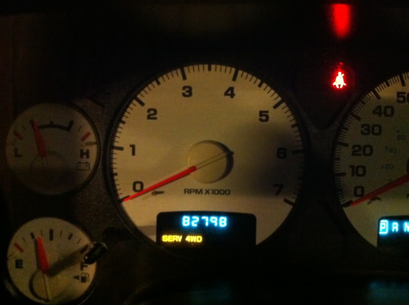
The error showing on the dash
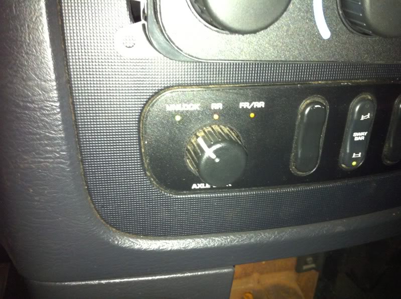
The third light from the left (to right) is flashing (FR/RR).

The voltage measured on the wires is 5v this is the seam as the rear axle. Is that the right voltage?
I hope this helps for you to help my friend.
Many thanks.
The error code given is C1450 which should a front axle error.
Here i have a couple of photo's
The error showing on the dash
The third light from the left (to right) is flashing (FR/RR).
The voltage measured on the wires is 5v this is the seam as the rear axle. Is that the right voltage?
I hope this helps for you to help my friend.
Many thanks.
Last edited by DutchPowerWagon; Sep 19, 2012 at 05:59 AM.

Champion
Joined: Aug 2006
Posts: 4,489
Likes: 4
From: New Jersey
C1450 Front Differential Position Sensor Circuit High
Is what I see.
All I can find online is this:
http://www.vipertruckregistry.com/sc...R-SM-Part1.pdf
Specifically Page 214 (just search for the term C1450 and you will get there)
Looks like its a problem with the stabilizer bar.
There are steps in that link that should help you.
hope that might help?
Last edited by Izero; Sep 19, 2012 at 08:29 AM.
Here is the written diagnost from the 2005 FSM, unfortutunately, the pinouts don't come with the copy, I STRONGLY SUGGEST, downloading the FSM---its free---from Weedahoe, in his sig, this FSM---it will take you step by step through the diagnostics, to get you up and running again
C1450-FRONT DIFFERENTIAL POSITION SENSOR CIRCUIT HIGH (CONTINUED)
C1450-FRONT DIFFERENTIAL POSITION SENSOR CIRCUIT HIGH (CONTINUED)
For a complete wiring diagram
Refer to Section 8W.
�
When Monitored:
Ignition on. Axle Locker Switch in the FR/RR position.
�
Set Condition:
The FDCM detects that the Front Differential Position Sensor is shorted to voltage.
Possible Causes
(T522) FRONT LOCKER SENSOR SENSE SHORTED TO BATTERY VOLTAGE
FRONT DIFFERENTIAL POSITION SENSOR
(T522) FRONT LOCKER SENSOR SENSE OPEN
(T522) FRONT LOCKER SENSOR SENSE SHORTED TO (T521) LOCKER SENSOR SUPPLY
FDCM
FRONT DIFFERENTIAL POSITION SENSOR
(T522) FRONT LOCKER SENSOR SENSE OPEN
(T522) FRONT LOCKER SENSOR SENSE SHORTED TO (T521) LOCKER SENSOR SUPPLY
FDCM
Diagnostic Test
1.
ACTIVE DTC
CAUTION: Before removing the FDCM harness connector, clean the connector and locking cam area of dirt
and debris. Failure to do so can result in the connector being jammed or damage to the locking cams on
the harness connector or module. Do not force the assist arm when releasing or installing the harness connector.
Ignition on, engine not running.
With the DRBIII
With the DRBIII
T, read DTCs.
Is the DTC active at this time?
Yes
Yes
>> Go To 2
No
>> Go To 7
2.
(T522) FRONT LOCKER SENSOR SENSE SHORTED TO BATTERY VOLTAGE
NOTE: Before continuing with the below diagnostic test, ensure
the FDCM harness connector seal is installed correctly. Inspect
the terminals on both harness connector and the module for
damage. Failure to do so can result in misdiagnoses of the system.
NOTE: Before continuing with the below diagnostic test, ensure
the FDCM harness connector seal is installed correctly. Inspect
the terminals on both harness connector and the module for
damage. Failure to do so can result in misdiagnoses of the system.
Turn the ignition off.
Disconnect the Front Locker Solenoid harness connector.
Disconnect the FDCM harness connector.
Turn the ignition on.
Measure the voltage on the (T522) Front Locker Sensor Sense circuit
in the FDCM harness connector.
Disconnect the Front Locker Solenoid harness connector.
Disconnect the FDCM harness connector.
Turn the ignition on.
Measure the voltage on the (T522) Front Locker Sensor Sense circuit
in the FDCM harness connector.
Does the voltmeter indicate voltage present?
Yes
Yes
>> Repair the short to voltage in the (T522) Front Locker
Sensor Sense circuit.
Perform FDCM VERIFICATION TEST.
Sensor Sense circuit.
Perform FDCM VERIFICATION TEST.
No
>> Go To 3
DR/DH
DIFFERENTIAL & DRIVELINE - ELECTRICAL DIAGNOSTICS 3 - 47
C1450-FRONT DIFFERENTIAL POSITION SENSOR CIRCUIT HIGH (CONTINUED)
3.
FRONT DIFFERENTIAL POSITION SENSOR OPERATION
Turn the ignition off.
Connect the FDCM harness connector.
Ignition on, engine not running.
Using a jumper wire, jumper across from the (T522) Front Locker Sensor Sense circuit and the (T521) Locker Sensor
Supply circuit in the Front Locker Solenoid harness connector.
While monitoring the sensor state on the DRBIII
Connect the FDCM harness connector.
Ignition on, engine not running.
Using a jumper wire, jumper across from the (T522) Front Locker Sensor Sense circuit and the (T521) Locker Sensor
Supply circuit in the Front Locker Solenoid harness connector.
While monitoring the sensor state on the DRBIII
T, tap the jumper wire on and off the (T522) Front Locker Sensor
Sense circuit terminal. Hold the jumper wire on and off the terminal for a minimum of 3 seconds.
Sense circuit terminal. Hold the jumper wire on and off the terminal for a minimum of 3 seconds.
Does the state change on the DRBIII
T while tapping the terminal?
Yes >> Replace the Front Locker Solenoid.
Perform FDCM VERIFICATION TEST.
Yes >> Replace the Front Locker Solenoid.
Perform FDCM VERIFICATION TEST.
No
>> Go To 4
4.
(T522) FRONT LOCKER SENSOR SENSE CIRCUIT OPEN
Turn the ignition off.
Disconnect the FDCM harness connector.
Measure the resistance of the (T522) Front Locker Sensor Sense circuit
between the Front Locker Solenoid harness connector and the
FDCM harness connector.
Disconnect the FDCM harness connector.
Measure the resistance of the (T522) Front Locker Sensor Sense circuit
between the Front Locker Solenoid harness connector and the
FDCM harness connector.
Is the resistance below 5.0 ohms?
Yes
Yes
>> Go To 5
No
>> Repair the open in the (T522) Front Locker Sensor Sense
circuit.
Perform FDCM VERIFICATION TEST.
circuit.
Perform FDCM VERIFICATION TEST.
3 - 48 DIFFERENTIAL & DRIVELINE - ELECTRICAL DIAGNOSTICS
DR/DH
C1450-FRONT DIFFERENTIAL POSITION SENSOR CIRCUIT HIGH (CONTINUED)
5.
(T522) FRONT LOCKER SENSOR SENSE CIRCUIT SHORTED TO (T521) LOCKER SENSOR SUPPLY
Measure the resistance between the (T522) Front Locker Sensor
Sense circuit and the (T521) Locker Sensor Supply circuit in the
FDCM harness connector.
Sense circuit and the (T521) Locker Sensor Supply circuit in the
FDCM harness connector.
Is the resistance below 5.0 ohms?
Yes
Yes
>> Repair the short between the Front Locker Sensor Sense
circuit and the (T521) Locker Supply Sensor circuit.
Perform FDCM VERIFICATION TEST.
circuit and the (T521) Locker Supply Sensor circuit.
Perform FDCM VERIFICATION TEST.
No
>> Go To 6
6.
FDCM
NOTE: Before continuing, check the FDCM harness connector terminals for corrosion, damage, or terminal
push out. Repair as necessary.
NOTE: Before continuing, check the FDCM harness connector terminals for corrosion, damage, or terminal
push out. Repair as necessary.
Using the schematics as a guide, inspect the wire harness and connectors. Pay particular attention to all Power and
Ground circuits.
Ground circuits.
Were there any problems found?
Yes
Yes
>> Repair as necessary.
Perform FDCM VERIFICATION TEST
Perform FDCM VERIFICATION TEST
No
>> Replace and program the Final Drive Control Module in accordance with Service Information.
Perform FDCM VERIFICATION TEST.
Perform FDCM VERIFICATION TEST.
7.
INTERMITTENT WIRING AND CONNECTORS
The conditions necessary to set this DTC are not present at this time.
Using the schematics as a guide, inspect the wiring and connectors specific to this circuit.
Wiggle test the wiring harness and connectors while checking for shorted and open circuits.
Using the DRBIII
Using the schematics as a guide, inspect the wiring and connectors specific to this circuit.
Wiggle test the wiring harness and connectors while checking for shorted and open circuits.
Using the DRBIII
T, monitor the data related to this circuit while performing the wiggle test. Look for the data to
change or for the DTC to reset.
change or for the DTC to reset.
Were there any problems found?
Yes
Yes
>> Repair as necessary.
Perform FDCM VERIFICATION TEST.
Perform FDCM VERIFICATION TEST.
No >> Test Complete.
Champion
Joined: Aug 2006
Posts: 4,489
Likes: 4
From: New Jersey

Trending Topics
I would almost be willing to bet that what is happening is a wire was pinched during the engine change out, and now, the control module is seeing a direct short to sensor, causing a higher than expected voltage back to the module------in other words, look for a damaged wire.
Just my best guess with out any hands on.
Just my best guess with out any hands on.