

Electric cooling fans, the right way.


Thread Starter
|
Captain
Joined: Nov 2007
Posts: 671
Likes: 0
From:
Well, I wanted to put this in the DIY forum, but I don't know how to post there, so it's goin' here.
Anyway, thisSunday afternoon was the install of the electric cooling fans in my '78 Aspen. I grew tired of the noisy, dangerous,power and fuel economy stealing flex fan that had been installed before I got it. I considered going with a clutch fan, but figured why not go all the way. However, this time I had the presence of mind to chronicle the upgrade.
First, we'll cover the reasons for going electric, for some of our members who may not understand the benefit. Mechanical fans operate all the time, whether they're flex fans or clutch fans. Flex fans will flatten out as RPM increases (henceflex fan), while clutch fans slip. Anyone who's ever had a clutch fan lock up can attest to the effectiveness of reducing fan resistance at higher RPM. Problem is, at cruising speed, both types of mechanical fan are working at pretty much full capacity, which means they're drawing power from your engine. Chevrolet hascome out with a visco-electric fan clutch that is computer controlled and can virtually turn off the fan. But most vehicles with mechanical fans will have drag on the engine at all times. Well, when you're cruising down the road at any decent speed, your motion is forcing air through the radiator. You don't need the fan. Cooling fans are only needed when moving at low speeds or not at all. This is why we go electric. You still draw power from the engine when they're on, it's just from loading the alternator instead of a direct mechanical draw. But electric fans can be turned off when they're not needed. This means improved performance and better fuel economy, sometimes as much as 15%.
Now, we've all seen hillbilly installs with the fans zip-tied to the radiator and nothing more than atoggle switch drawing power straight from the battery. Some folks go the next step and install a relay and maybe even a fuse. Then there's the thermal switchesyou can buy that use a probe to control the fans automatically. These work great, but way too often people are lazy and simply jam the probe into the radiator core between the fins. When you do that, they're not detecting actual coolant temperature; usually reading much lower. And inevitably, most of these installs are a mess of zippyties, electrical tape and crimp connectors.
I decided I would share my install process step-by-step, so that some of our less experienced members may get information on how to install electric fans the correct way.
The first step for installing electric cooling fans is selecting the fan itself. Those 10", 12" and 16" fans you find at Checker or Autozone are fine as auxilliary units to aid a flex or clutch fan that just doesn't flow enough air at idle on hot days. But these things usually will not effectively cool an engine by themselves. Then there are thehigh quality aftermarket fans designed specifically to replace mechanical fans, and these things work great. Problem is, they're expensive. It has been my experience that $200 for the fan alone is on the low end for one that will get the job done. My preference? Find OEM electric fans at the salvage yard that were used on a similar sized radiator, and preferably fora similar sized engine. Being that most newer cars have smaller engines than the old stuff with the mechanical fans we're trying to replace, you just have to do the best you can. The upside is that most of the electric fansmove a lot more air than a flex or clutch fan does at idle, which is when we need them. When prowling the yards for fans, make sure you go armed with the measurements you need to prevent an "ah, ****" moment when you go to stuff the thing in your car and it hits the water pump pulley or somesuch. Height, width and depth. For my Aspen, the radiator core measured 18.5" tall by 26" wide, with 5.75" from the core to the water pump pulley bolts. The fan I selected came from a '99 Concorde with a 3.2 literV-6 and measures 16" tall by 26" wide by 4" deep; a near-perfect fit. When you take your fan out of the salvage car, cut the connector a couple inches back on the harness side so that you can use it on your car. Also a good idea to grab the relays, especially because the bone yard will probably throw them in for free, rather than paying $6 or $8 each at the parts store.
Once you have found the fans you need and purchased them, you'll most likely have to make some modifications. If you really did your homework, it won't take too much. In my case, all that was necessary was removal of the old mounting points, which can be seen already separated from the housing ala reciprocating saw:

Next, you'll have to fab upyour own mounts. Usually pretty easy if you have a modicum of fabrication skills. I used 16 gauge sheet steel:

Then simply attach them however you had previously planned out. Since my fans were almost exactly the width of my radiator, I had to notch the housing where the mounting tabs were to be attached:

Now simply install the fan assembly:

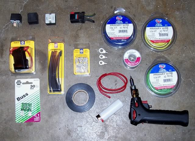
Now the fun part (actually, I do enjoy it): The wiring. This is one part where it pays to be attentive and maticulous. Map everything out first, so that all your wires are the correct length and routed in such a way that they won't cause problems down the road. I personally draw a schematic first and mock install all components before I start cutting. To do wiring that will last year after year, throw away the butt connectors and wire nuts. Solder and shrink wrap are your friend. It takes a little (lot) longer, but you won't be chasing opens or cooking fuses with shorts in a few short years. It's fine to use crimp connectors, especially since working on wiring already in a vehicle it can be nearly impossible to hold both wires, the soldering iron and the solder. Just be sure you do solder them.
Once you have mocked up the harness, it's time to assemble it. Again, take your time and do it right.

Now earlier I mentioned the automatic fan control assemblies, which are simple thermal switches. They can be bought at most parts stores for about $20 and they do work. Unfortunately, most of them do use the probes that require ~2' of capillary tube that cannot be shortened, so you just have to coil it up.

They are designed to be inserted in the upper radiator hose, which is what I did until I have time to search out a fitting that will allow them to be installed in the radiator tank itself, where the plug is visible in the photo. (Ignore the bungee's on the battery, as a real hold down is one of those things I keep forgetting to pick up for this car.[sm=headbang.gif] ) The two in the photo are the adjustable kind that will allow you to set your fans to come on anywhere from 150 to 250 degrees farenheight. Many of the thermal switches that install in intake manifold ports (my preference) are not adjustable. They are, however, much more professional looking. Most thermal switches for this type of application are built to turn off 15 degrees cooler than the on setting so that the fans aren't cycling only seconds apart. I used two switches to control the two speeds of the Cocorde fans. The low speed is set to come on at 185 degrees, the high speedkicks in at 200 degrees.
Now, on to discussing relays. Most of us know what they are, but a surprising number of people don't know how they work. Relays are basically switches, but their design is such that a large current can be controlled using a very small one. The way a relay works is with an electomagnet that moves an arm when it is energized. The small current is what energizes the electromagnet coils. The arm that moves with the electromagnet is what closes the high current circuit. The high current side has full time voltage supply, but the component on the relay circuit only gets that power when the switch is closed (turned on) by energizing the relay's coil. Relays allow the tiny wires and contacts of your ignition switch that can probably only handle 10 or 15 amps to control the vehicle's fuel pump, starter solenoidand other high draw components. Modern computer controlled cars supply the relay coil's power side at key on, and the PCM controls the ground side. Older vehicles typically have the relays grounded full time and use the power side of the coil to energize. This is how mine are set up.
The thermal switches that I used can be wired directly to the fans, but I opted to use relays in the interest of preserving the function of those switches. Most cars that are equipped with electric fans will only use two relays (one for each speed), but since older cars are not equipped with PCM's that will shut down the entire fan circuit at key off, I recommend the use of a third relay to control power to the thermal switches.
Excuse the zippy ties; I had the relays epoxied to the bracket, but broke them off during install. Later this week I'll be fabbing a new braket with clips to hold the relays.

I have the relays set up so that key on power energizes the center relay, which in turn supplies voltage to the thermal switches. The thermal switches control the high and low speed relays,whichsupply power to the fan motors. All three relays get theirconstant power directly from the battery, with an in-line 30 amp maxi fuse. All relays and the fan motors are grounded to the radiator support, which also has a ground strap from the battery. Good grounds are critical, as a poor ground connection will cause low draw components to be inoperative or high draw components to try to ground through smaller wires, which can and does cause vehicle fires.
This electric conversion works exactly as planned, turning the fans on at 185 degrees and off at 170 degrees. Idling in my garage with an ambient temperature of 62 degrees, the fans were on for 60-75 seconds and off for 50-60 seconds. Cruising down the road at 55 MPH, my engine runs a nice 170-180 degrees, so the fans will not come on. On a100 degree day sitting in trafic, they'll probably be one all the time, but should still keep the engine under 200 degrees. We'll find out in 7 or 8 months.
Well, that pretty much concludes this piece. I hope someone has found it useful, as I wish I had been given adviceon the proper way to do electrical repair or modification when I was first tinkering with my cars. Would've savedme lots of trouble.[ ]
]
BelowI have posted a photograph of the wiring schematic I drafted for this two speed fan set-up, if anyone desires to use an existing template. (god, I wish I had a decent draw program on this PC, one with which I don't have to draw in unusual shapes after printing[:@]). It doesn't show up well in this image, but the relay terminals are numbered. Most any relay will have four or five terminals labeled 30, 85, 86 and 87 (add 87a for five terminal units). 30 is your full time hot, 85 is your key-on hot, 86 is ground and 87 is the supply for the component. 87a on 5 terminal relays will supply battery voltage to whatever it is connected towhen the relay is not energized. 87a is usually the center terminal.

Edit:
Just so no one is laughing and saying "why bother with an Aspen, this is the car:

And underhood:

Anyway, thisSunday afternoon was the install of the electric cooling fans in my '78 Aspen. I grew tired of the noisy, dangerous,power and fuel economy stealing flex fan that had been installed before I got it. I considered going with a clutch fan, but figured why not go all the way. However, this time I had the presence of mind to chronicle the upgrade.
First, we'll cover the reasons for going electric, for some of our members who may not understand the benefit. Mechanical fans operate all the time, whether they're flex fans or clutch fans. Flex fans will flatten out as RPM increases (henceflex fan), while clutch fans slip. Anyone who's ever had a clutch fan lock up can attest to the effectiveness of reducing fan resistance at higher RPM. Problem is, at cruising speed, both types of mechanical fan are working at pretty much full capacity, which means they're drawing power from your engine. Chevrolet hascome out with a visco-electric fan clutch that is computer controlled and can virtually turn off the fan. But most vehicles with mechanical fans will have drag on the engine at all times. Well, when you're cruising down the road at any decent speed, your motion is forcing air through the radiator. You don't need the fan. Cooling fans are only needed when moving at low speeds or not at all. This is why we go electric. You still draw power from the engine when they're on, it's just from loading the alternator instead of a direct mechanical draw. But electric fans can be turned off when they're not needed. This means improved performance and better fuel economy, sometimes as much as 15%.
Now, we've all seen hillbilly installs with the fans zip-tied to the radiator and nothing more than atoggle switch drawing power straight from the battery. Some folks go the next step and install a relay and maybe even a fuse. Then there's the thermal switchesyou can buy that use a probe to control the fans automatically. These work great, but way too often people are lazy and simply jam the probe into the radiator core between the fins. When you do that, they're not detecting actual coolant temperature; usually reading much lower. And inevitably, most of these installs are a mess of zippyties, electrical tape and crimp connectors.
I decided I would share my install process step-by-step, so that some of our less experienced members may get information on how to install electric fans the correct way.
The first step for installing electric cooling fans is selecting the fan itself. Those 10", 12" and 16" fans you find at Checker or Autozone are fine as auxilliary units to aid a flex or clutch fan that just doesn't flow enough air at idle on hot days. But these things usually will not effectively cool an engine by themselves. Then there are thehigh quality aftermarket fans designed specifically to replace mechanical fans, and these things work great. Problem is, they're expensive. It has been my experience that $200 for the fan alone is on the low end for one that will get the job done. My preference? Find OEM electric fans at the salvage yard that were used on a similar sized radiator, and preferably fora similar sized engine. Being that most newer cars have smaller engines than the old stuff with the mechanical fans we're trying to replace, you just have to do the best you can. The upside is that most of the electric fansmove a lot more air than a flex or clutch fan does at idle, which is when we need them. When prowling the yards for fans, make sure you go armed with the measurements you need to prevent an "ah, ****" moment when you go to stuff the thing in your car and it hits the water pump pulley or somesuch. Height, width and depth. For my Aspen, the radiator core measured 18.5" tall by 26" wide, with 5.75" from the core to the water pump pulley bolts. The fan I selected came from a '99 Concorde with a 3.2 literV-6 and measures 16" tall by 26" wide by 4" deep; a near-perfect fit. When you take your fan out of the salvage car, cut the connector a couple inches back on the harness side so that you can use it on your car. Also a good idea to grab the relays, especially because the bone yard will probably throw them in for free, rather than paying $6 or $8 each at the parts store.
Once you have found the fans you need and purchased them, you'll most likely have to make some modifications. If you really did your homework, it won't take too much. In my case, all that was necessary was removal of the old mounting points, which can be seen already separated from the housing ala reciprocating saw:
Next, you'll have to fab upyour own mounts. Usually pretty easy if you have a modicum of fabrication skills. I used 16 gauge sheet steel:
Then simply attach them however you had previously planned out. Since my fans were almost exactly the width of my radiator, I had to notch the housing where the mounting tabs were to be attached:
Now simply install the fan assembly:
Now the fun part (actually, I do enjoy it): The wiring. This is one part where it pays to be attentive and maticulous. Map everything out first, so that all your wires are the correct length and routed in such a way that they won't cause problems down the road. I personally draw a schematic first and mock install all components before I start cutting. To do wiring that will last year after year, throw away the butt connectors and wire nuts. Solder and shrink wrap are your friend. It takes a little (lot) longer, but you won't be chasing opens or cooking fuses with shorts in a few short years. It's fine to use crimp connectors, especially since working on wiring already in a vehicle it can be nearly impossible to hold both wires, the soldering iron and the solder. Just be sure you do solder them.
Once you have mocked up the harness, it's time to assemble it. Again, take your time and do it right.
Now earlier I mentioned the automatic fan control assemblies, which are simple thermal switches. They can be bought at most parts stores for about $20 and they do work. Unfortunately, most of them do use the probes that require ~2' of capillary tube that cannot be shortened, so you just have to coil it up.
They are designed to be inserted in the upper radiator hose, which is what I did until I have time to search out a fitting that will allow them to be installed in the radiator tank itself, where the plug is visible in the photo. (Ignore the bungee's on the battery, as a real hold down is one of those things I keep forgetting to pick up for this car.[sm=headbang.gif] ) The two in the photo are the adjustable kind that will allow you to set your fans to come on anywhere from 150 to 250 degrees farenheight. Many of the thermal switches that install in intake manifold ports (my preference) are not adjustable. They are, however, much more professional looking. Most thermal switches for this type of application are built to turn off 15 degrees cooler than the on setting so that the fans aren't cycling only seconds apart. I used two switches to control the two speeds of the Cocorde fans. The low speed is set to come on at 185 degrees, the high speedkicks in at 200 degrees.
Now, on to discussing relays. Most of us know what they are, but a surprising number of people don't know how they work. Relays are basically switches, but their design is such that a large current can be controlled using a very small one. The way a relay works is with an electomagnet that moves an arm when it is energized. The small current is what energizes the electromagnet coils. The arm that moves with the electromagnet is what closes the high current circuit. The high current side has full time voltage supply, but the component on the relay circuit only gets that power when the switch is closed (turned on) by energizing the relay's coil. Relays allow the tiny wires and contacts of your ignition switch that can probably only handle 10 or 15 amps to control the vehicle's fuel pump, starter solenoidand other high draw components. Modern computer controlled cars supply the relay coil's power side at key on, and the PCM controls the ground side. Older vehicles typically have the relays grounded full time and use the power side of the coil to energize. This is how mine are set up.
The thermal switches that I used can be wired directly to the fans, but I opted to use relays in the interest of preserving the function of those switches. Most cars that are equipped with electric fans will only use two relays (one for each speed), but since older cars are not equipped with PCM's that will shut down the entire fan circuit at key off, I recommend the use of a third relay to control power to the thermal switches.
Excuse the zippy ties; I had the relays epoxied to the bracket, but broke them off during install. Later this week I'll be fabbing a new braket with clips to hold the relays.
I have the relays set up so that key on power energizes the center relay, which in turn supplies voltage to the thermal switches. The thermal switches control the high and low speed relays,whichsupply power to the fan motors. All three relays get theirconstant power directly from the battery, with an in-line 30 amp maxi fuse. All relays and the fan motors are grounded to the radiator support, which also has a ground strap from the battery. Good grounds are critical, as a poor ground connection will cause low draw components to be inoperative or high draw components to try to ground through smaller wires, which can and does cause vehicle fires.
This electric conversion works exactly as planned, turning the fans on at 185 degrees and off at 170 degrees. Idling in my garage with an ambient temperature of 62 degrees, the fans were on for 60-75 seconds and off for 50-60 seconds. Cruising down the road at 55 MPH, my engine runs a nice 170-180 degrees, so the fans will not come on. On a100 degree day sitting in trafic, they'll probably be one all the time, but should still keep the engine under 200 degrees. We'll find out in 7 or 8 months.
Well, that pretty much concludes this piece. I hope someone has found it useful, as I wish I had been given adviceon the proper way to do electrical repair or modification when I was first tinkering with my cars. Would've savedme lots of trouble.[
]BelowI have posted a photograph of the wiring schematic I drafted for this two speed fan set-up, if anyone desires to use an existing template. (god, I wish I had a decent draw program on this PC, one with which I don't have to draw in unusual shapes after printing[:@]). It doesn't show up well in this image, but the relay terminals are numbered. Most any relay will have four or five terminals labeled 30, 85, 86 and 87 (add 87a for five terminal units). 30 is your full time hot, 85 is your key-on hot, 86 is ground and 87 is the supply for the component. 87a on 5 terminal relays will supply battery voltage to whatever it is connected towhen the relay is not energized. 87a is usually the center terminal.
Edit:
Just so no one is laughing and saying "why bother with an Aspen, this is the car:
And underhood:

Joined: Jan 2008
Posts: 33
Likes: 0
From:
if you use an aftermarket water temp gauge teltek has an electric gauge that also has a built in switch you digitaly program on and off temp and it sends the signal to relays. wonderful peice for about 130.oo
