Engine check light issues
#21
for those who have been watching..from Oldmarine on another board.
My understanding of the evaporative emission system *purge* and *test* is as follows (see the attached schematic diagram):
At some point shortly after the engine is started, the PCM (2) will open the *Canister Purge Solenoid* (10) to clear accumulated vapors from the canister (6). At the same time, it will command the Vent Valve (5 – part of the Leak Detection Pump unit) to open allowing fresh air to enter the canister as the vapors are being purged.
The* leak detection cycle test* is controlled by the PCM (2), but it will not do this until the engine is at operating temperature and in closed loop operation (in closed loop, the PCM is controlling fuel delivery to the engine based on the heated O2 sensor signals). During the leak detection cycle test, the purge solenoid (10) is closed, and the *Leak Detection Pump* (5) is commanded to pressurize the evaporative emission components to a very low pressure (less than ½ psi) and then maintain this pressure. (The leak detection pump uses manifold vacuum to operate the pump.)
When the leak detection pump stops pumping, the PCM assumes the desired pressure has been reached. The manual is not clear how long this pressure is maintained until the PCM determines there is no leak. If no leak, the canister purge solenoid is opened, and when the leak detection pump (detecting the loss in pressure) starts to run again the* test is considered successful *and is terminated.
If the system slowly loses pressure, the PCM decides whether this is a small leak or a large leak based on the rate of pressure loss (how often and how long the leak detection pump runs to maintain pressure), and it triggers an appropriate DTC and the check engine light. SEE diagram in previous post for what the numbers match
#22
Well, I foudn that All the tubes gong to the evap/purge canister and to the fuel leak detection pump were all wrong. Oldmarine helped me out with this.
I replaced most of the smaller diameter vacuum hoses on my 2003 Dakota a couple of years ago, and everything is working properly. This is how mine is set up:
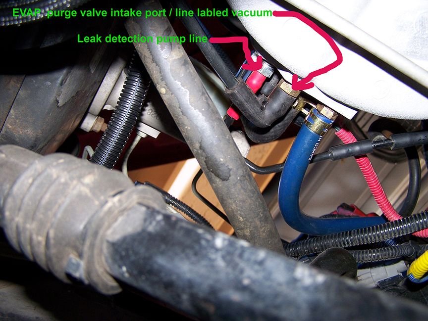
The large diameter hose from the canister is connected to the bottom of the leak detection pump, as you stated and showed in the images.
The smaller diameter hose from the canister has a servicing port with a schrader valve and green cap teed into it, and then it goes to one port of the purge solenoid (I can't tell which port without dismantling the setup because the hoses run behind/below the battery tray). The servicing port is where they connect the smoke machine to troubleshoot leaks.
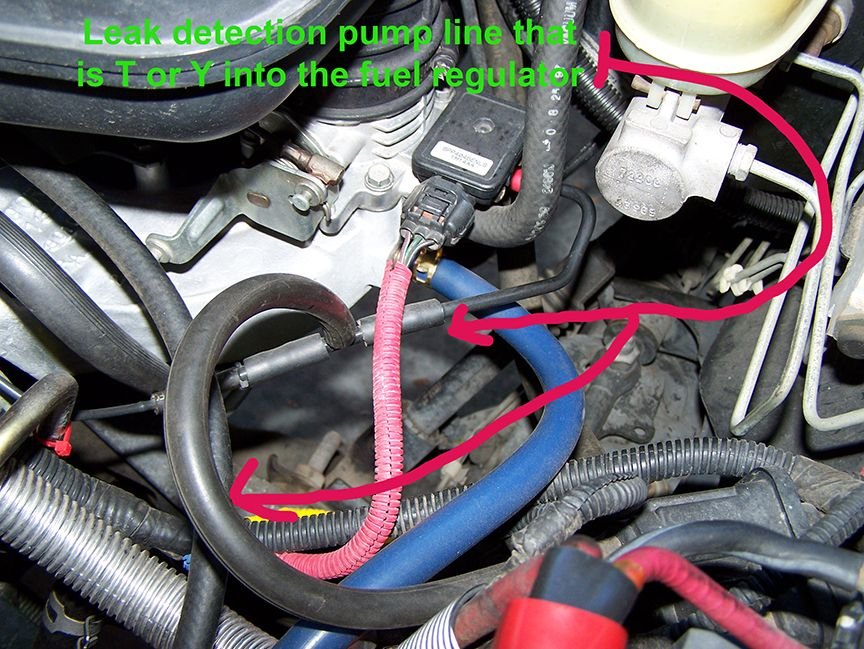
The vacuum hose coming from the throttle body has a tee fitting, one side going to the second port on the purge solenoid, and the other side going to the smaller port on the leak detection pump. In the schematic diagram, this would be the equivalent of teeing line 12 into line 10. So the leak detection pump gets its vacuum from the throttle body (like the purge solenoid) instead of from the intake manifold.
The U-shaped line from the top to the bottom of the leak detection pump is correct. This line is not shown on the schematic. Your new pump may come with this line already installed.
You said that the two lines from the purge solenoid were teed together and then to the throttle body vacuum port? That is definitely wrong.
And if the smaller line from the canister was connected to the leak detector pump, that is also wrong. That would mean that the leak detection pump has no vacuum source to perform its function. I would guess that would trigger the P1494 code, because the pump could not respond to the ECM commands.
I just checked my purge valve with a mirror, and the bottom port (furthermost from the electrical connector) is marked "VAC", so I'm sure I connected the line from the throttle body vacuum port to that port. My purge valve looks more like the pic you posted in the other thread, where the ports are more included in the body than projecting out like the picture above. Check on your purge valve to see if one of the ports is labeled
#23
Maybe good news. I got all the lines put back on per the above info and took her out for a test 50 mile run to re-set the emissions chip..got her home and NO check engine light. I'll take her out again tomorrow to be sure but so far so good.. all this hassle because idiot took the lines off and just shoved them back on any-old-way..##!!@@##**!!! and here's a schematic of the system..hope it makes sense and you can read it...
Basics: large tube from the fuel tank canister goes to the back side bottom on the fuel leak detector pump(FLDP))and other large tube comes from the filter and goes to the other side of the FLDP toward the bottom. The small tube coming from the fuel tank canister goes to the small port on the purge valve not marked "vac"..
The small tube coming from from the throttle intake the one with the "y" split in it and the green smoke tester cap..one leg goes to the solenoid pump/purge valve's port marked "vac" and the other goes to the FLDP's small port near it's top.
The FLEP is located on/actual screwed to it the battery tray's rear wall and the whole tray has to removed to get at it. The purge valve on my 2002 was located next to the battery and hung on a rubber sleeve that attached to the battery tray as well but was easy to take off w/o removing anything else.
AND AGAIN MANY THANKS TO Oldmarine!!!!
#28
WAHOO passed emissions test I am now legal..to drive it..THANKS FOR ALL THE HELP.. Now if I just get the FLDP back into place I just stuffed it into an open spot to run my check and didn't want to disturb anything before I got the actual emission test completed..It's a really poor design for maintenance. Like trying to fit a size 12 foot into a size 8 shoe!! The issue is that the fuse box is in the way and really can't be moved very far due to the large bundle of wires going in and out at the front AND back of the box. I didn't try tilting it up..just thought of that so that may solve the problem of reinstall for the FLDP!! I'll report back...
Last edited by rbg; 12-17-2016 at 09:26 AM.
#29


