Dodge Ram 1994-2001: How to Replace Emergency Brake
Have your emergency brake serviced, just like the rest of your brakes, to make sure it's working correctly when called upon to do its job.
This article applies to the Dodge Ram (1994-2001).
It can oftentimes be over looked, but the emergency brake will need to be serviced at some time during the life of your truck just like the rest of the brake system. The emergency brake has two major functions. As the name suggests, it is a back up brake just in case your other brakes fail for some reason. It is also used as a parking brake to keep your vehicle rolling away while you're not in it. Both of these functions are extremely important and can keep you from getting yourself in a horrible situation. This is why you want to make it a point to always ensure that your emergency brake is in good working order.
The emergency brake on a drum-disc-equipped truck is applied using the brake shoes on the rear brake assembly that are also used when you apply the brakes normally while driving. The only difference is that there is a cable that actuates them when you apply the emergency brake versus hydraulic pressure when you apply the brakes while driving. So, on a drum-brake-equipped truck, replacing the emergency brake is a matter of replacing the rear brake shoes.
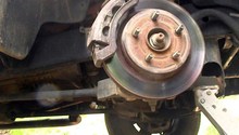
The emergency brake on a disc-brake-equipped truck works with shoes located inside of the rear brake rotors. When you apply the emergency brake from inside the truck, these shoes press on the inside of the brake rotor and keep the wheel from spinning. These shoes take quite a long time to wear out, but it is possible that they will someday need to be swapped out. A very common thing that wears them out prematurely is if someone tries to drive the truck with the emergency brake still applied. Another thing that can happen is, if they are not adjusted correctly, they can tend to drag causing them to always make contact with the rotor and wearing them out. So it's a good idea to either check the adjustment on the emergency brake from time to time or have someone check it.

Materials Needed
- Jack and jack stands
- Wheel lug nut
- Brake spring tool or channel lock pliers
- Hold down spring tool or needle nose pliers
- Mallet
When replacing the rear brake shoes, you must replace both sides at the same time. If you only change one side, then you will have uneven braking in the rear; this could lead to making your vehicle very difficult to control under braking.
Step 1 – Elevate vehicle and place securely on jack stands
Seeing as how you are only going to be working on the rear of the truck, it is only necessary to get the rear wheels off the ground. Make sure they are high enough off the ground so that you can remove the rear wheels.
(Related Article: How to Jack Up Your Dodge Ram - Dodgeforum.com)

Step 2 – Remove rear wheels
Using a breaker bar or an air impact wrench and the proper size socket, remove the wheel lug nuts that secure the rear wheel in place. Once you have removed the lug nuts, remove the rear wheel and place it out of the way.

Step 3 – Remove brake drum
The rear brake drum should be able to be slid off but might require a few taps with a mallet to free it up. If for some reason after tapping it with a mallet it still refuses to move, it is possible that the brake shoes might have dug into the brake drum. To free them up, you might need to loosen the adjuster that is located on the back inside the brake drum and can be accessed by an opening in the backing plate.

Step 4 – Clean off brake assembly with brake cleaner
Before beginning to work on the brake assembly make sure you give it a good cleaning with brake cleaner. This will make it much easier to work on the parts of the brake assembly.
Step 5 – Remove brake shoes
The first part of removing the shoes is to remove all of the springs and retainers which hold the shoes in place. It's quite a few steps, so make sure you have a firm understanding before you embark on this. After removing all of the springs and retainers, you will then have to disengage the emergency brake mechanism which will allow you to completely remove the shoes. That will be covered in a series of pictures after the removal of the springs and retainers.

1. Disengage the secondary shoe return spring from the anchor pin.

2. Disengage the primary shoe return spring from the anchor pin.

3. Push in on the hold-down retainer and turn it 90 degrees and remove the retainer, spring, and pin. There are two of these so make sure you do both sides.

4. Remove the spring from the parking brake lever.

5. Remove the adjuster spring and the shoe guide.

Now that you have all of the springs and retainers removed you can disengage the emergency brake mechanism which will allow you to remove the shoes. This next series of pictures should allow you to see just how you will go about doing that. Click on each image to enlarge.
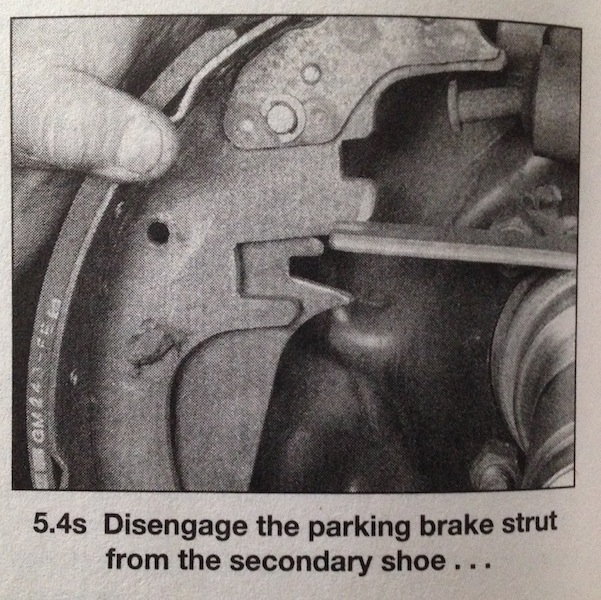
Figure 10. Disengage the strut from secondary shoe. 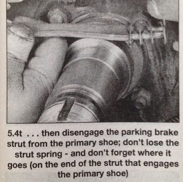
Figure 11. Disengage strut from primary shoe. 
Figure 12. Adjuster screw assembly. 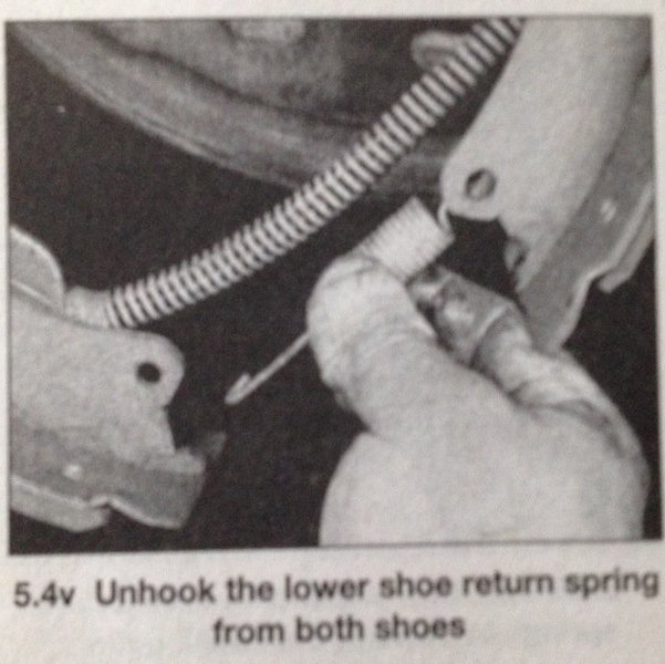
Figure 13. Lower shoe return spring.
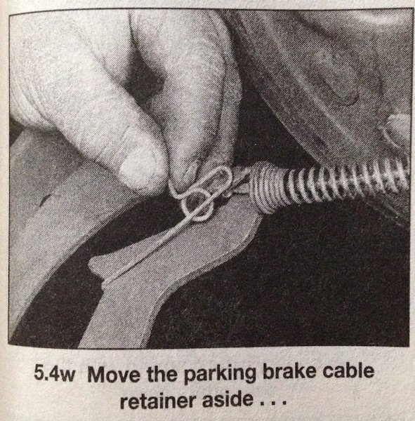
Figure 14. Cable retainer. 
Figure 15. Disengaging cable. 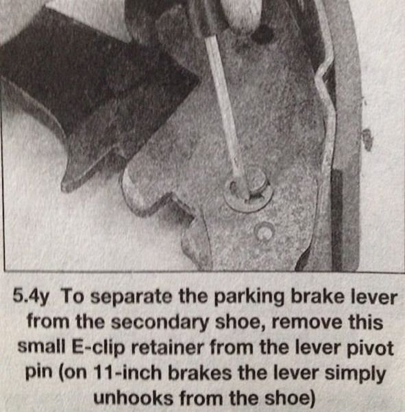
Figure 16. E-clip retainer. 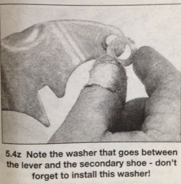
Figure 17. Don't forget about the washer.
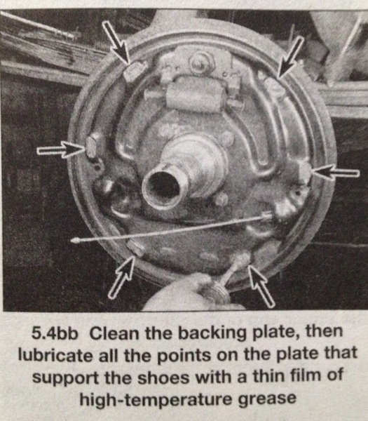
Step 6 – Prepare backing plate for new shoes
Before you install the new shoes, you will need to clean the backing plate and grease all the points that support the shoes. You will want to use a high-temperature brake grease for this.
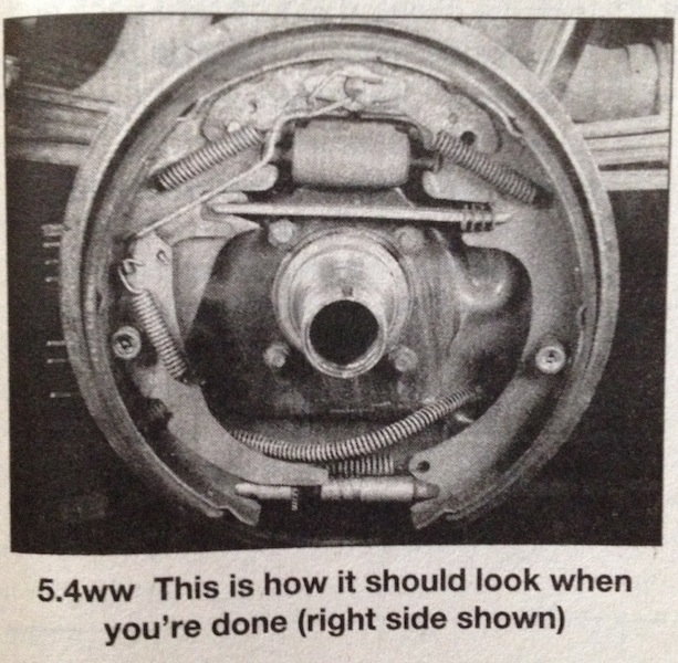
Step 7 – Install new shoes
Installation will be the same as removal. Follow the steps in reverse order. Make sure everything is nice and clean when you are installing it and make sure that anything that moves or pivots gets a slight bit of high-temperature grease.
Related Discussions
- Parking Brake Adjustment - Dodgeforum.com
- Rear Brakes and Wheel Cylinder Replacement - Dodgeforum.com