
My Official Solid Axle Swap Thread (The Project Writeup)
#11
 04-16-2010, 11:53 PM

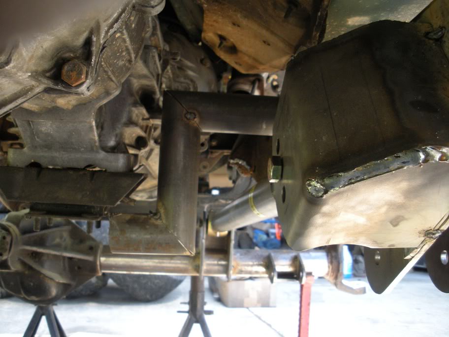
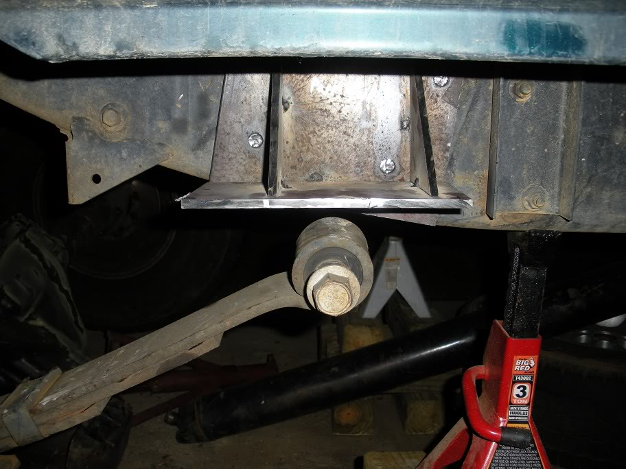
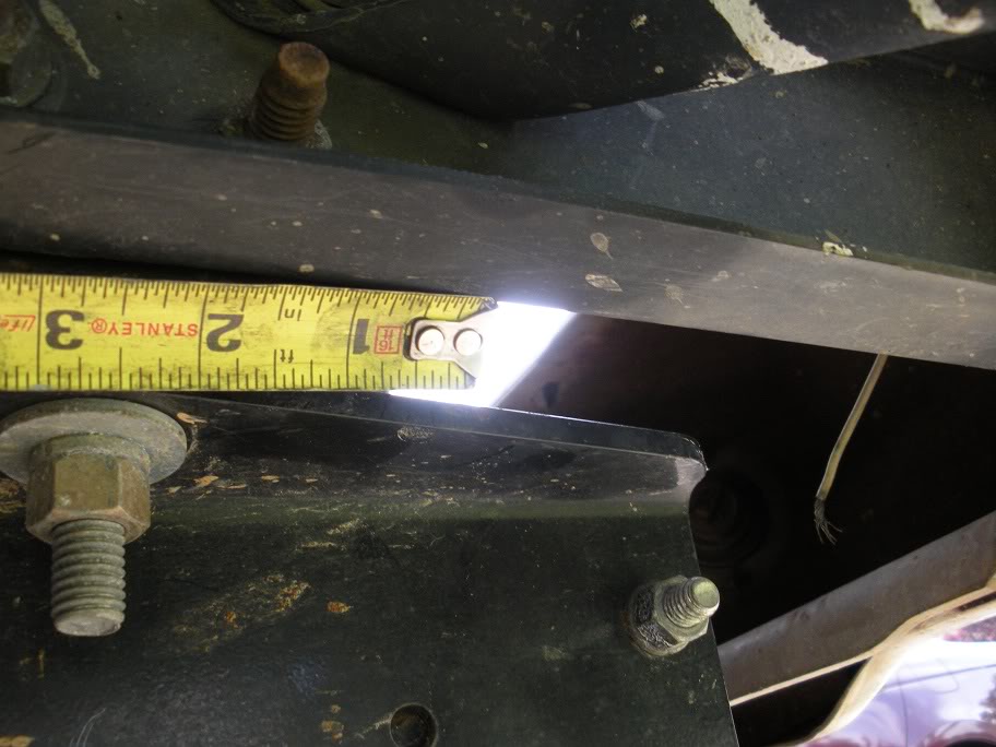
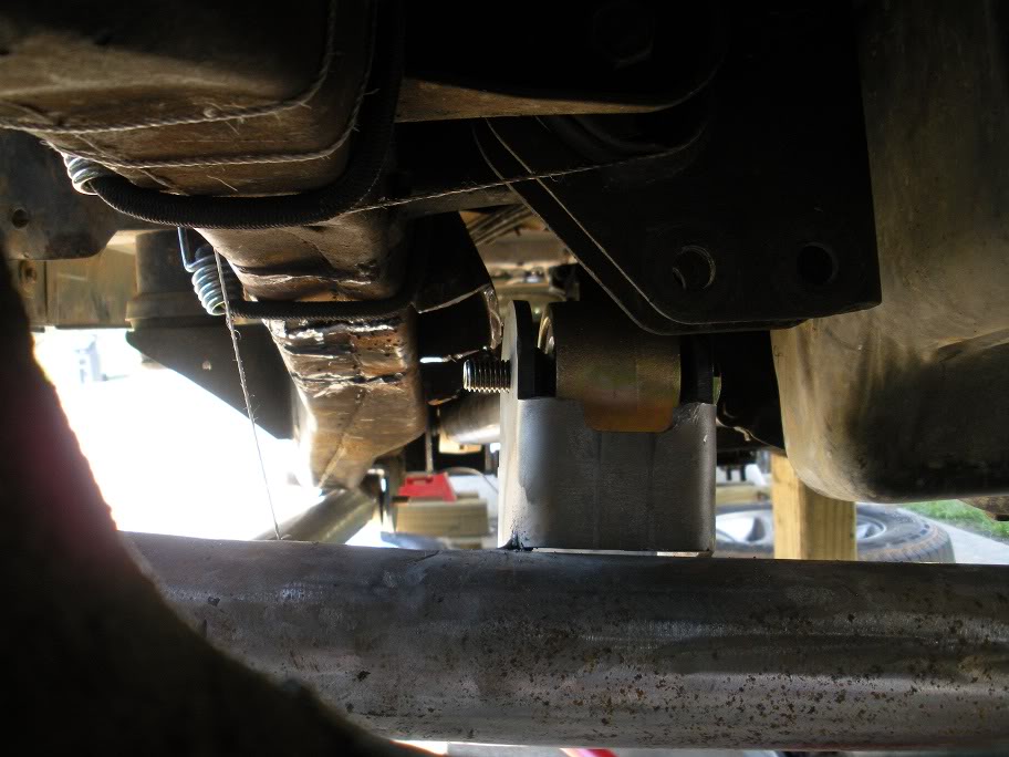
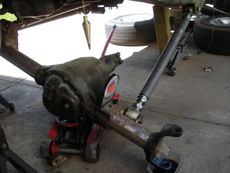
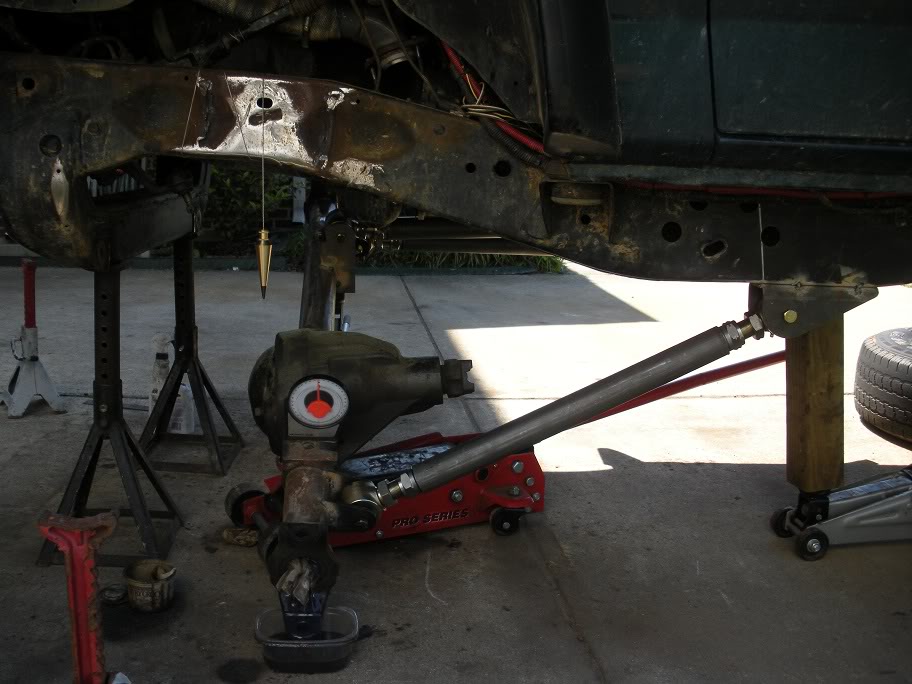
Next on the list is placing the upper link brackets to measure and cut the tube for the upper link.
So I started by figuring out how the upper frame link fit best to give me the most adjustment and clearance around my transmission crossmember. I decided to place it here...
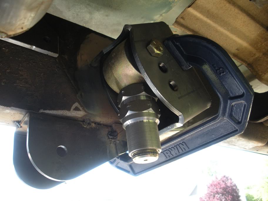
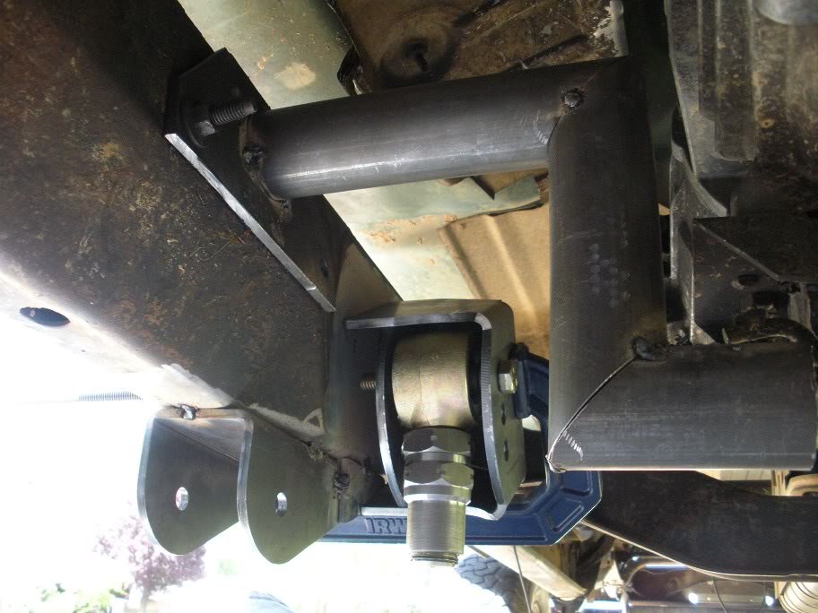
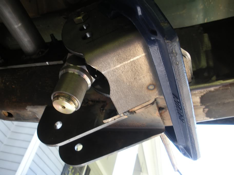
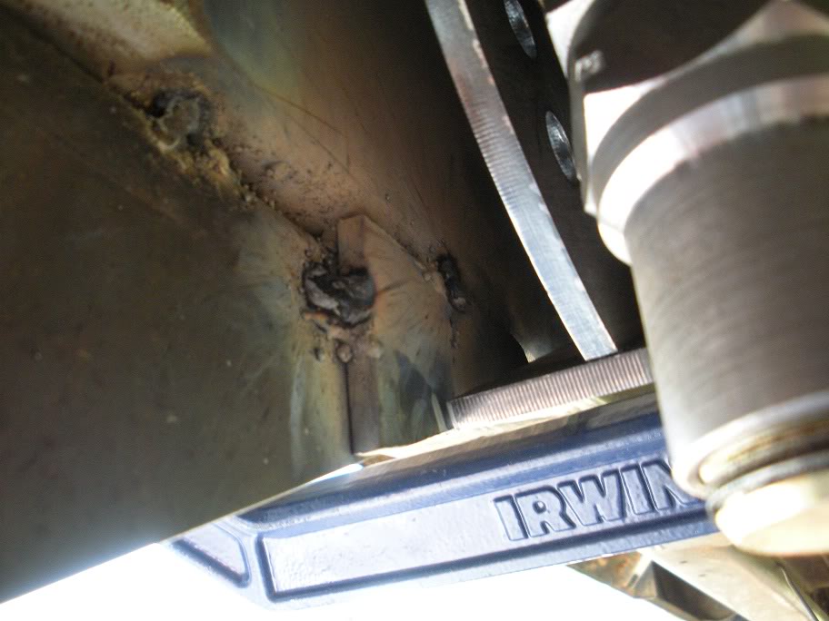
If you recall, when placing the lower link frame mounts, I made the outside of the mount flush with the outside of the frame, so I had to put in a little spacer to fit the upper link frame mount flush...
So I started by figuring out how the upper frame link fit best to give me the most adjustment and clearance around my transmission crossmember. I decided to place it here...
If you recall, when placing the lower link frame mounts, I made the outside of the mount flush with the outside of the frame, so I had to put in a little spacer to fit the upper link frame mount flush...
Last edited by 95_318SLT; 05-11-2010 at 07:36 PM.
#12
04-22-2010, 04:01 PM
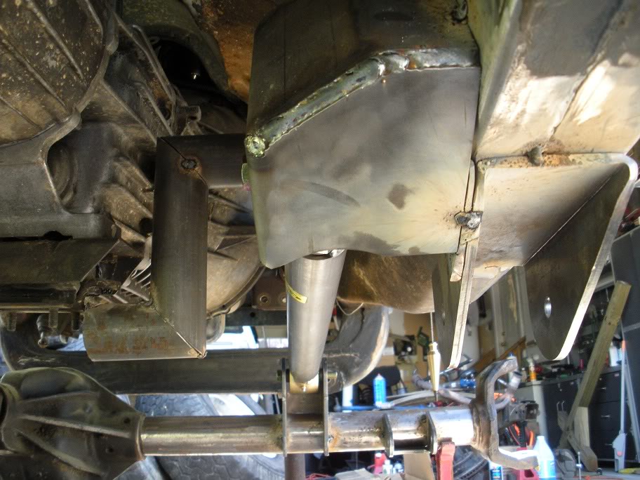
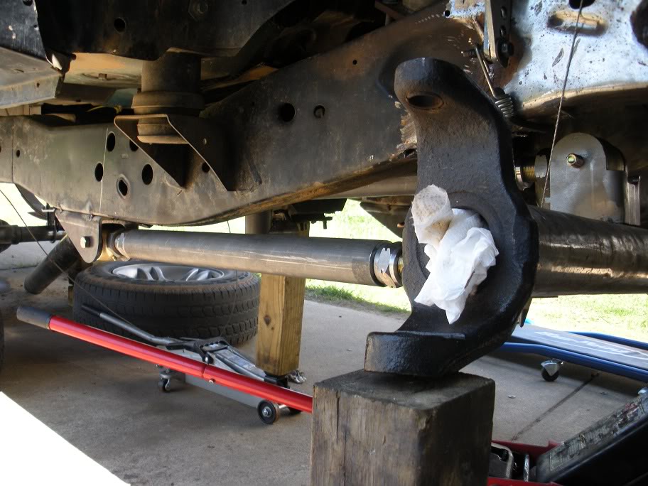
And once that one was placed, I used a johnny joint and the remaining tube to line up the upper link axle mount and tacked it in place...
Then I welded the spacer on, welded the upper link frame mount together and tacked it in place...
After taking measurements between the mounts and cut the upper link tube and fit it...
Then I welded the spacer on, welded the upper link frame mount together and tacked it in place...
After taking measurements between the mounts and cut the upper link tube and fit it...
Last edited by 95_318SLT; 05-11-2010 at 07:38 PM.
#13
04-22-2010, 09:32 PM
Now on to the rear axle...
So to match the height of the front, I decided to do a shackle flip with custom hangers and longer shackles. Also, because of measurement changes due to changing angles and mounting points of the spring, the factory leaf springs from my truck would have pushed the front axle over an inch forward in the wheel well, and having the tire not centered in the wheel well just doesn't sit well with me!!
So I used this chart...
http://littlekeylime.com/MrN/mrnimages/leaf_springs.png
... to find springs that had dimensions that better suited my new set up. I ended up picking leaf springs from a '97-'03 F150. The springs are 2.5 inches longer than ours, so I should get a little bit better articulation, and the length difference is in the front of the spring (front eye to center pin), so that made it easy to push the axle back to where it needed to be.
So to start, I cut the 4 leaf spring hangers off the frame. They are held in place by what are called huck bolts. They are a tight press fit into the frame. I cut a cross in the head of each one and knocked the heads off with an air hammer. That allowed me to knock the hangers off and left the body of the bolts...
So the next step is to cut the body off as close to the frame rail as possible, and grind the rest down flush with the frame rail...
The next step is to take a flat head punch and hammer and knock the rest of the huck bolt out...


I then designed and built my own set of custom hangers. I started by using the factory hangers to line up the mount holes. They need to have a near-zero tolerance... there can be no play in the leaf spring hangers!!!!
I came up with a fairly simple design and tacked everything together (pictures to come)...
So to match the height of the front, I decided to do a shackle flip with custom hangers and longer shackles. Also, because of measurement changes due to changing angles and mounting points of the spring, the factory leaf springs from my truck would have pushed the front axle over an inch forward in the wheel well, and having the tire not centered in the wheel well just doesn't sit well with me!!
So I used this chart...
http://littlekeylime.com/MrN/mrnimages/leaf_springs.png
... to find springs that had dimensions that better suited my new set up. I ended up picking leaf springs from a '97-'03 F150. The springs are 2.5 inches longer than ours, so I should get a little bit better articulation, and the length difference is in the front of the spring (front eye to center pin), so that made it easy to push the axle back to where it needed to be.
So to start, I cut the 4 leaf spring hangers off the frame. They are held in place by what are called huck bolts. They are a tight press fit into the frame. I cut a cross in the head of each one and knocked the heads off with an air hammer. That allowed me to knock the hangers off and left the body of the bolts...
So the next step is to cut the body off as close to the frame rail as possible, and grind the rest down flush with the frame rail...
The next step is to take a flat head punch and hammer and knock the rest of the huck bolt out...
I then designed and built my own set of custom hangers. I started by using the factory hangers to line up the mount holes. They need to have a near-zero tolerance... there can be no play in the leaf spring hangers!!!!
I came up with a fairly simple design and tacked everything together (pictures to come)...
Last edited by 95_318SLT; 05-11-2010 at 07:39 PM.
#14
04-25-2010, 08:46 PM
*****Be sure to read through the entire thread before you put any stock in these next two posts... this info needs to be corrected later, but I'm not changing these next two posts so that you can learn from my mistakes!******
With the rear shackle hangers done, its time to get the new leaf springs squared up under the truck and the front hangers lined up and welded together.
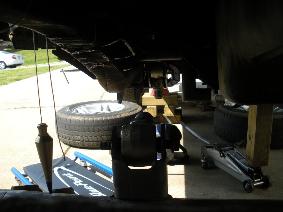
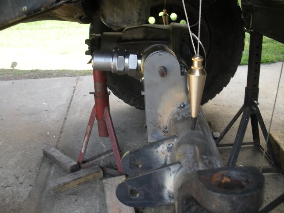
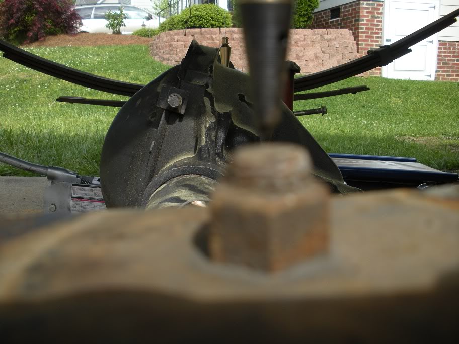
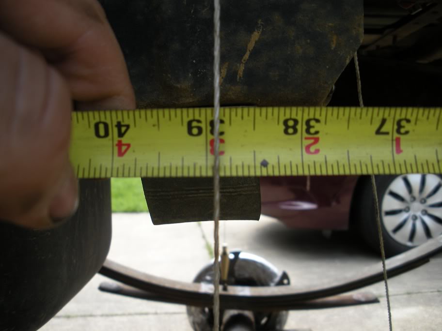
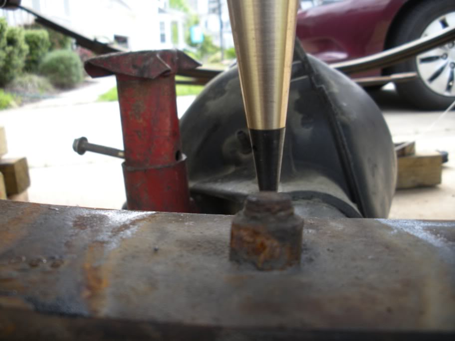
I started by bolting the new hangers to the frame. On the passenger side, I measured out and marked the center of the wheel well. This is the point that the leaf spring "center pin" needs to line up with.
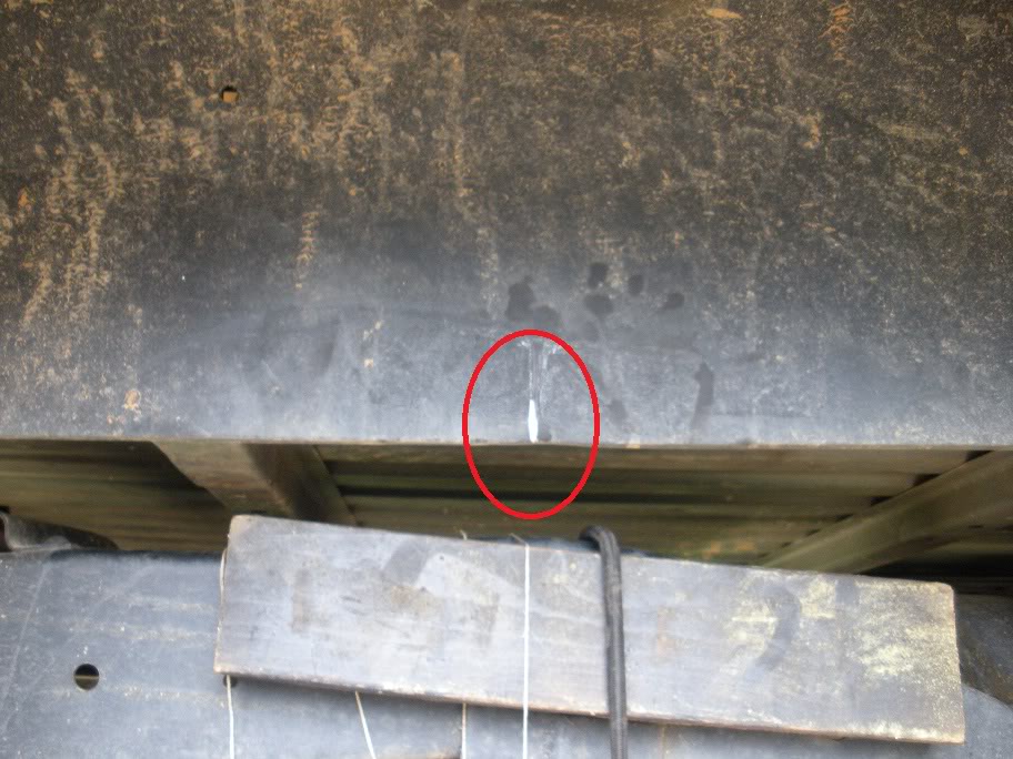
Next, I hung a plumb bob from that point down to where the center pin will go.
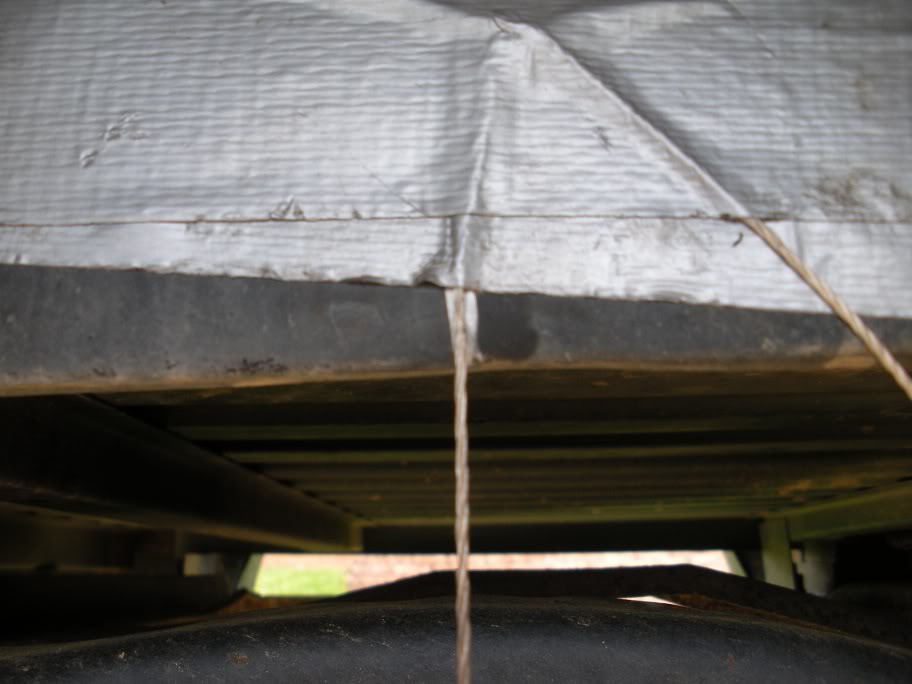
Next, I hung the and hung the shackle and rear of the spring from the rear shackle hanger on the passenger side.
Next, I lined up the center pin with the plumb bob.
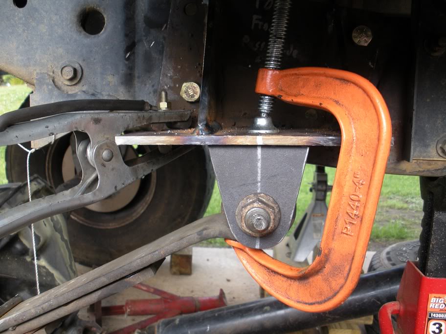
Next, I bolted the front hanger tabs to the front eye of the leaf spring and clamped it to the front hanger, making sure that the center pin stayed lined up with the plumb bob and tacked them in place.
And here is a wider view...
With the rear shackle hangers done, its time to get the new leaf springs squared up under the truck and the front hangers lined up and welded together.
I started by bolting the new hangers to the frame. On the passenger side, I measured out and marked the center of the wheel well. This is the point that the leaf spring "center pin" needs to line up with.
Next, I hung a plumb bob from that point down to where the center pin will go.
Next, I hung the and hung the shackle and rear of the spring from the rear shackle hanger on the passenger side.
Next, I lined up the center pin with the plumb bob.
Next, I bolted the front hanger tabs to the front eye of the leaf spring and clamped it to the front hanger, making sure that the center pin stayed lined up with the plumb bob and tacked them in place.
And here is a wider view...
Last edited by 95_318SLT; 05-11-2010 at 07:40 PM.
#15
04-26-2010, 09:18 PM
So that was the easy part! Next, the other side needs to be matched up. This means making measurements that can be more accurately matched on the other side since measuring the center of the wheel well was a fairly rough measure (and who knows if the body is really bolted to the frame straight!!).
So what I decided to do was untape the plumb bob from the wheel well and hang it from the frame rail, making sure it was still lined up with the center pin in its new location. Then, I measure from the end of the frame rail to the plumb bob string on the passenger side.
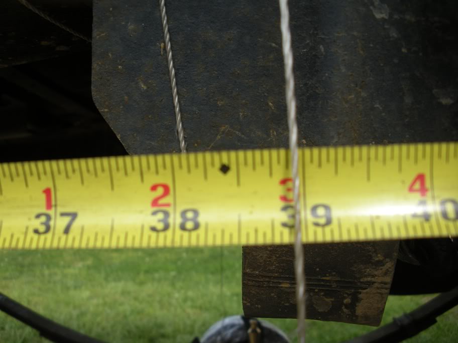
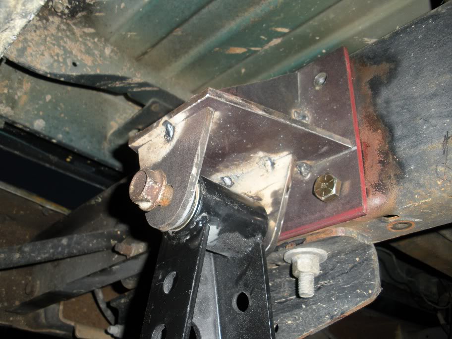
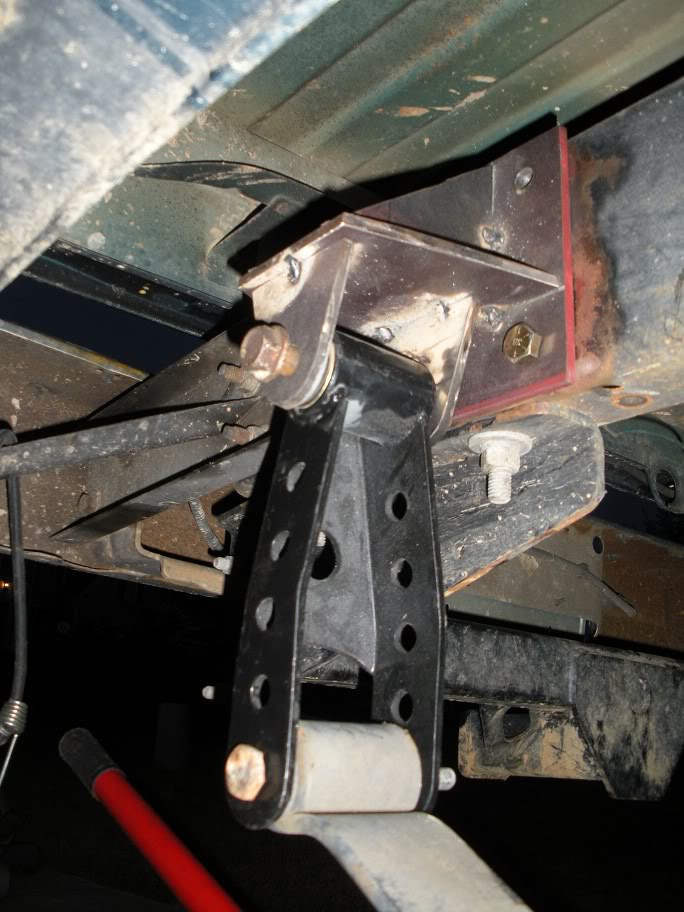
Next, the drivers side shackle and leaf spring need to be bolted to the rear hanger. The measurement taken on the passenger side needs to be matched and the leaf spring centered.
With this side centered, the front hanger tabs need to be mounted, clamped and tack welded on in the same fasion as the other side.
After both sides are tacked on, pick some other points along the frame that can be positively matched on both sides and double and triple check the measurements. After several measurements, I decided I was satisfied that the springs were squared up.
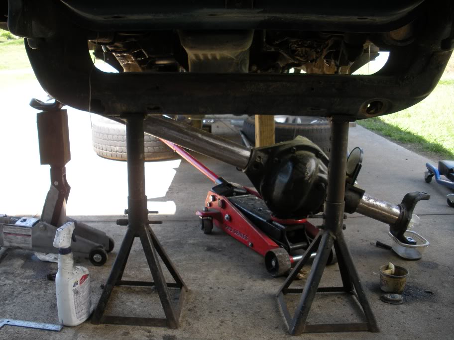
Here are some wider shots of the newely placed springs...
So next I can finish welding up the front hangers and hang the rear axle from the leaf spring! Then I can finally get my first glimpse of how tall the truck should sit with weight on the springs!!
So what I decided to do was untape the plumb bob from the wheel well and hang it from the frame rail, making sure it was still lined up with the center pin in its new location. Then, I measure from the end of the frame rail to the plumb bob string on the passenger side.
Next, the drivers side shackle and leaf spring need to be bolted to the rear hanger. The measurement taken on the passenger side needs to be matched and the leaf spring centered.
With this side centered, the front hanger tabs need to be mounted, clamped and tack welded on in the same fasion as the other side.
After both sides are tacked on, pick some other points along the frame that can be positively matched on both sides and double and triple check the measurements. After several measurements, I decided I was satisfied that the springs were squared up.
Here are some wider shots of the newely placed springs...
So next I can finish welding up the front hangers and hang the rear axle from the leaf spring! Then I can finally get my first glimpse of how tall the truck should sit with weight on the springs!!
Last edited by 95_318SLT; 05-11-2010 at 07:40 PM.
#16
04-29-2010, 08:23 PM
Well, this is why these write ups are always good to have to go off of... this is the part where you get to learn from my mistakes! Being as this is the first time I've ever tried to custom fabricate suspension, there were some key things that I didn't know to think about.
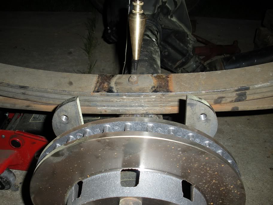
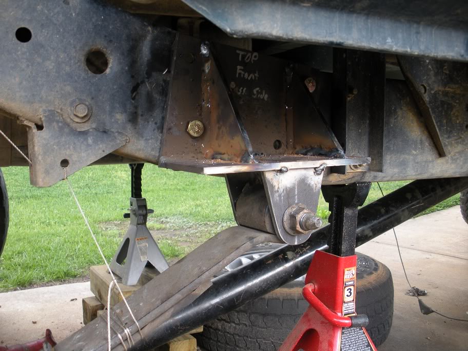
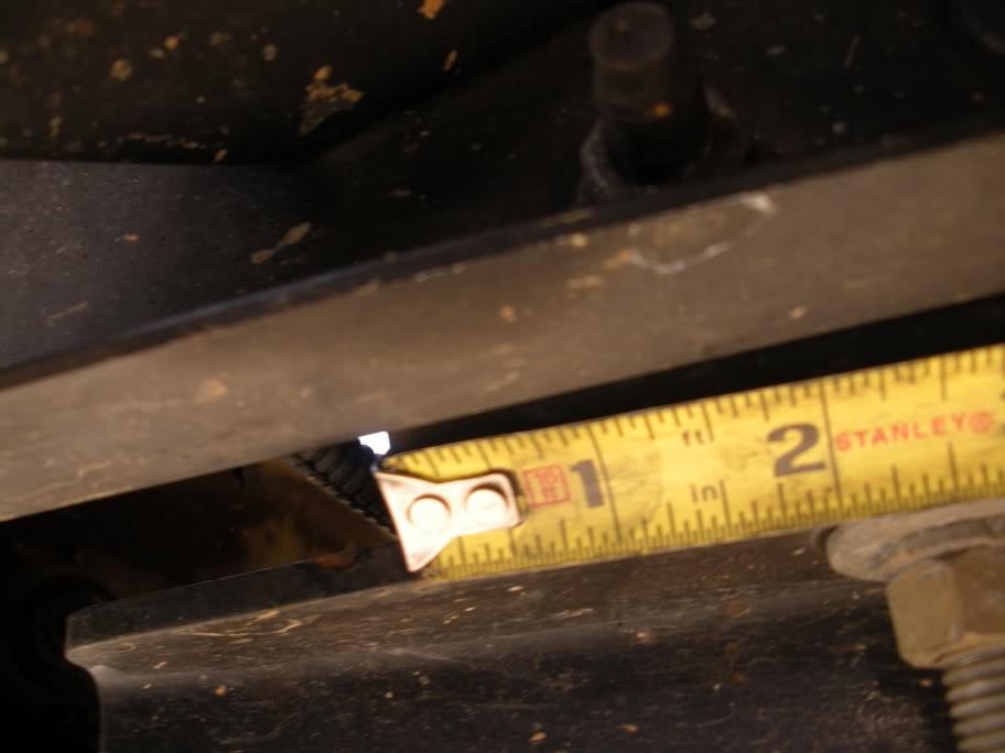
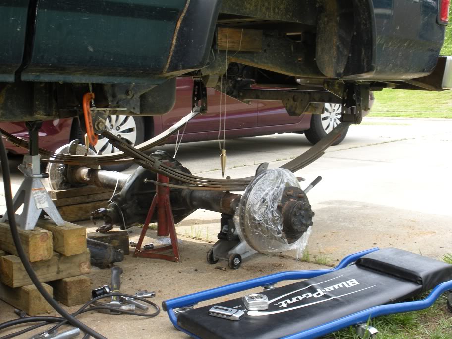
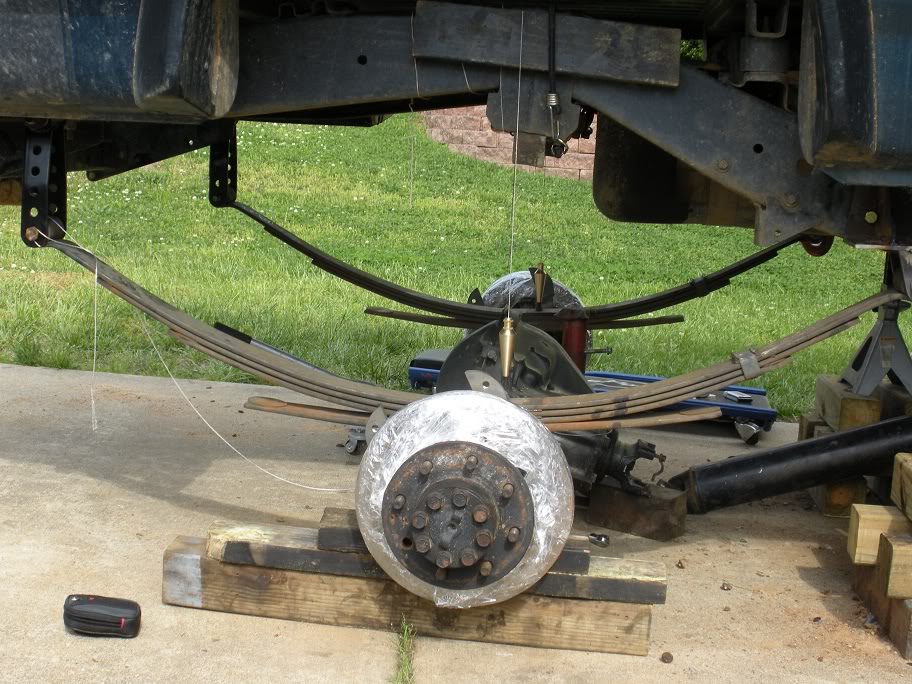
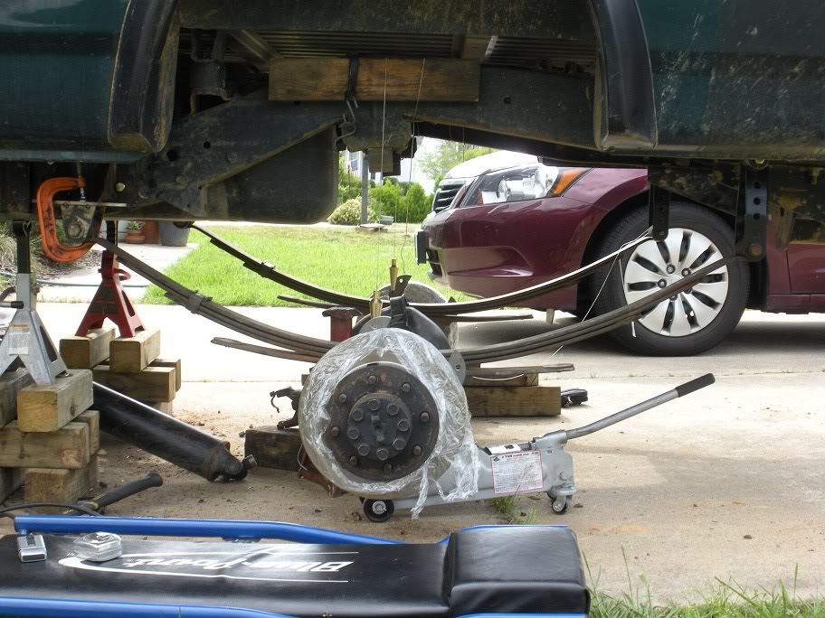
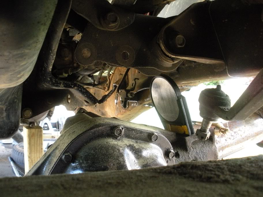
As posted in the last few posts, I centered the rear axle by lining everything up unsprung. I got the the spring mounts all welded up and bolted on tight and slid my jack under the axle and jacked it up to see where it would sit sprung (I jacked it up until all the weight was off the jackstands... full weight on the leaf springs). That is where the problem is! Here are some pictures... see if you spot the issue before I tell you :P
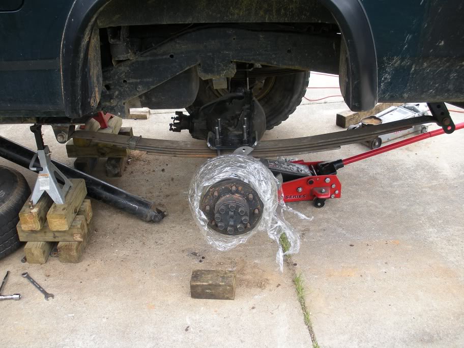
Lol, if that last one didn't give it away, then you aren't very observant! It appears as though when the leaf springs flexxed up so they were fully sprung, the center bolt moved back 1.75". I spent all that time making sure the center pin was centered in the wheel well with the spring in th wrong position!! I never really gave much thought to leaf springs staying straight and even while flexxing before! So what I'm going to have to do now is cut my hangers up and slide the mounting tabs forward and re-weld them. I also spent some time in AutoCad drawing up the spring angles and determining how to fix them best since I have to fix them anyway...
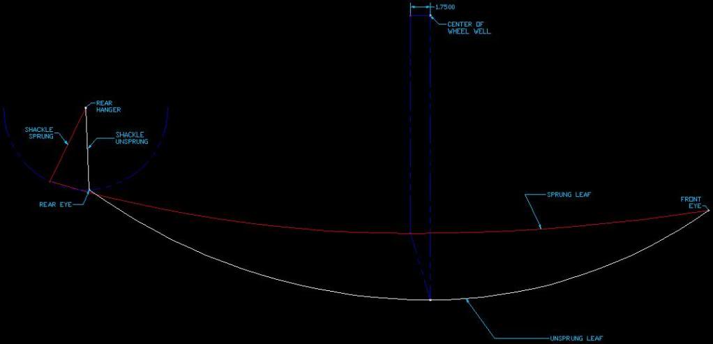

With that second design, I'll gain an inch of clearance in the wheel well while shortening the shackle at the same time, which will give me more of an angle on the leaf spring which will in-turn shorten the distance that the axle moves back and forth while flexxing. So in laymens terms... design two is much better!
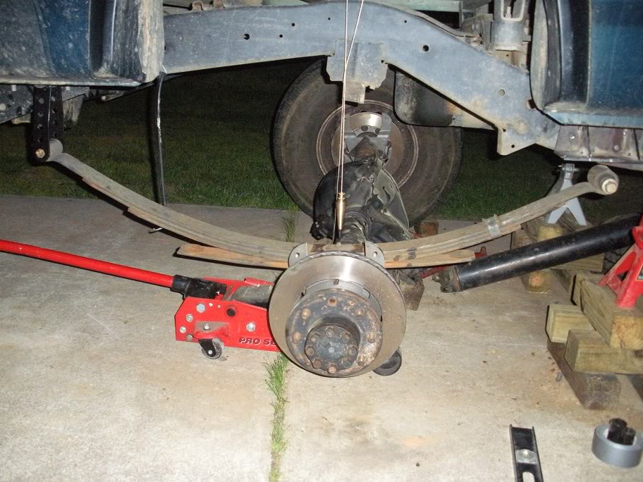
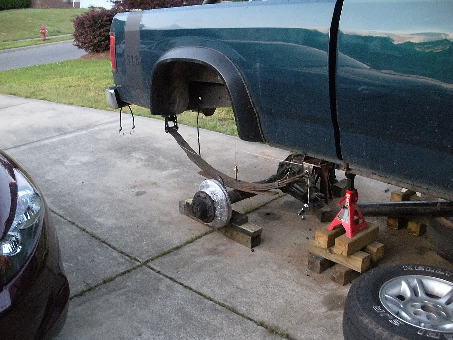
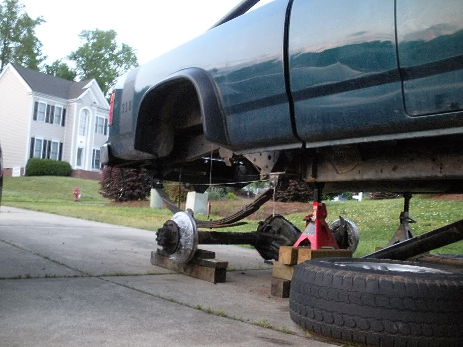
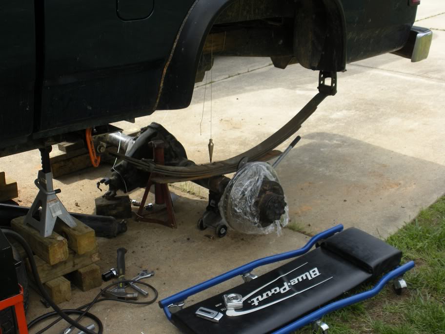
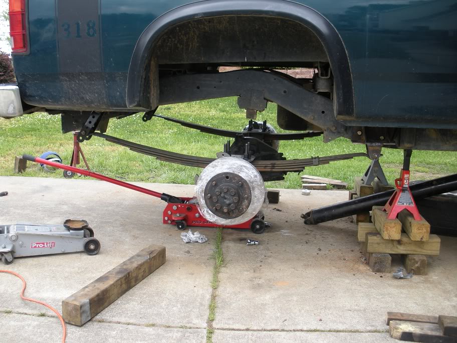
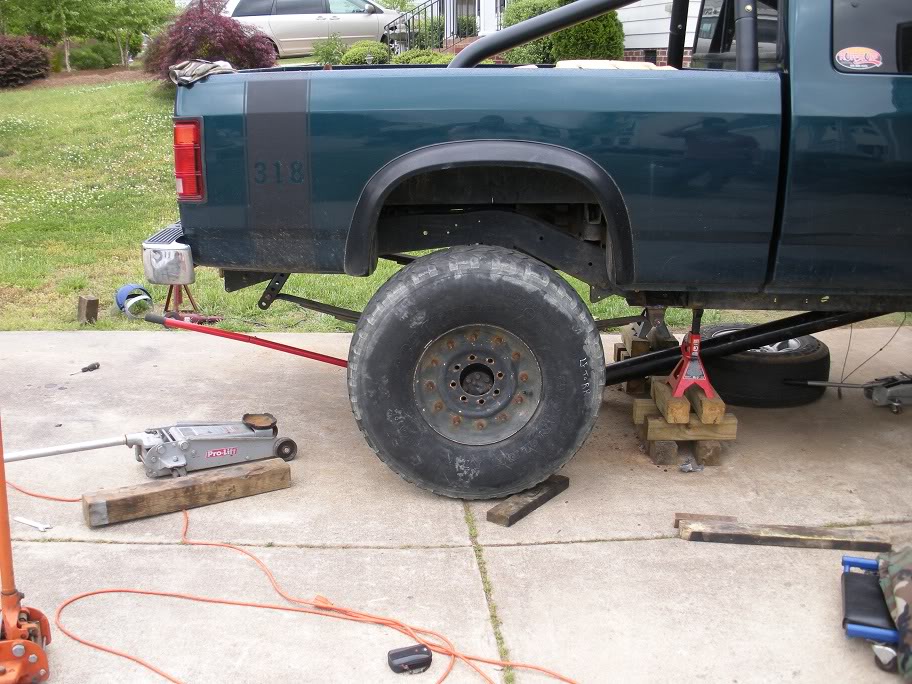
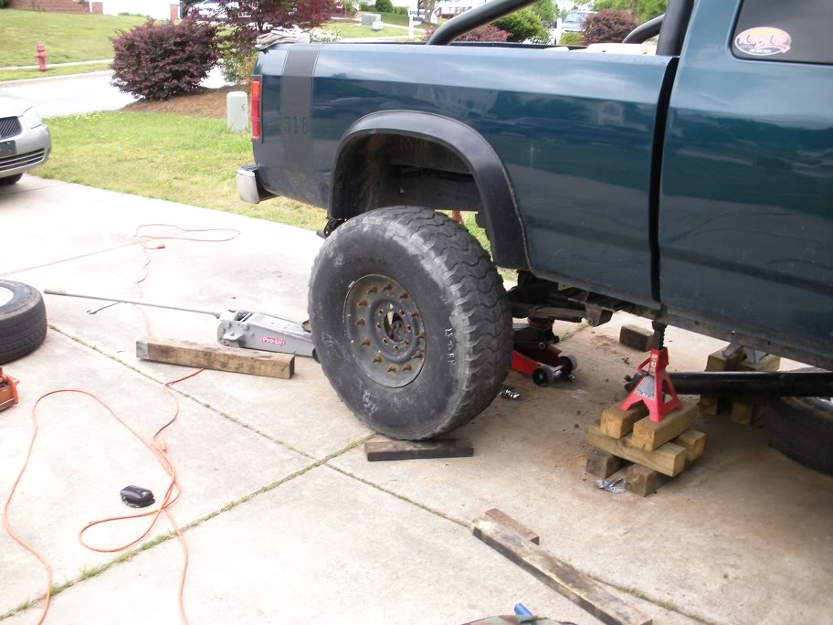
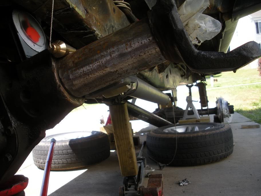
But on a brighter note, I finally got to see where the truck would finally sit when its finally off jackstands again. This would be the minimum height, seeing as though I can always get more leafs to add to the pack. The front has a lot of adjustment, so I'll level the front with wherever the back ends up!
As you can see here, the truck is going to have to go up about 3 more inches above what it is sitting on jackstands to fit the tires under it, so imagine the truck 3 inches above this...
As posted in the last few posts, I centered the rear axle by lining everything up unsprung. I got the the spring mounts all welded up and bolted on tight and slid my jack under the axle and jacked it up to see where it would sit sprung (I jacked it up until all the weight was off the jackstands... full weight on the leaf springs). That is where the problem is! Here are some pictures... see if you spot the issue before I tell you :P
Lol, if that last one didn't give it away, then you aren't very observant! It appears as though when the leaf springs flexxed up so they were fully sprung, the center bolt moved back 1.75". I spent all that time making sure the center pin was centered in the wheel well with the spring in th wrong position!! I never really gave much thought to leaf springs staying straight and even while flexxing before! So what I'm going to have to do now is cut my hangers up and slide the mounting tabs forward and re-weld them. I also spent some time in AutoCad drawing up the spring angles and determining how to fix them best since I have to fix them anyway...
With that second design, I'll gain an inch of clearance in the wheel well while shortening the shackle at the same time, which will give me more of an angle on the leaf spring which will in-turn shorten the distance that the axle moves back and forth while flexxing. So in laymens terms... design two is much better!
But on a brighter note, I finally got to see where the truck would finally sit when its finally off jackstands again. This would be the minimum height, seeing as though I can always get more leafs to add to the pack. The front has a lot of adjustment, so I'll level the front with wherever the back ends up!
As you can see here, the truck is going to have to go up about 3 more inches above what it is sitting on jackstands to fit the tires under it, so imagine the truck 3 inches above this...
Last edited by 95_318SLT; 05-11-2010 at 07:41 PM.
#17
04-30-2010, 03:39 PM
(Back to the front axle)
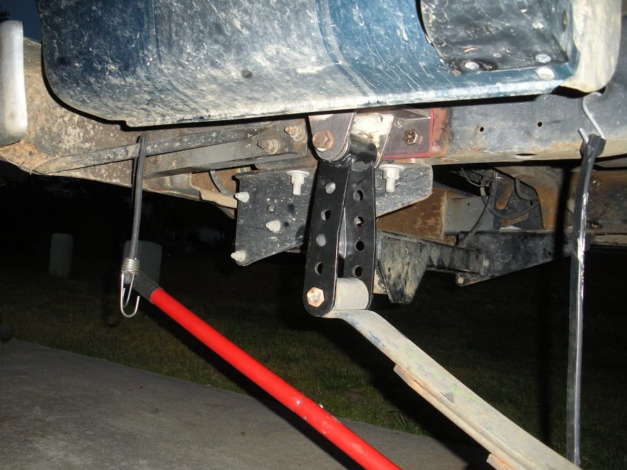
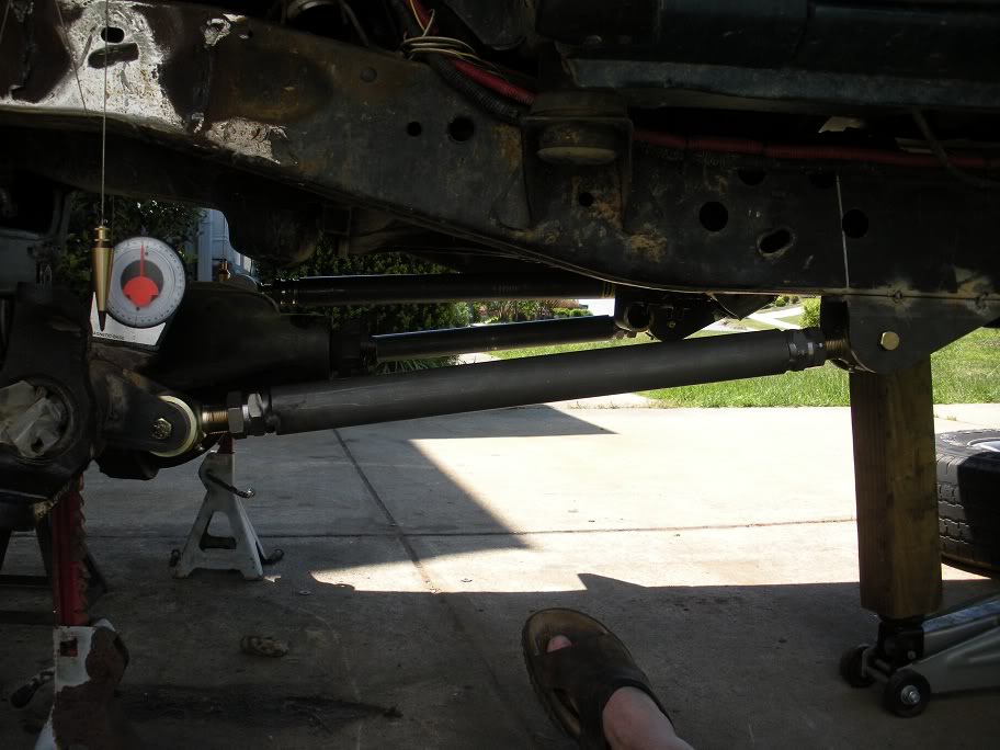
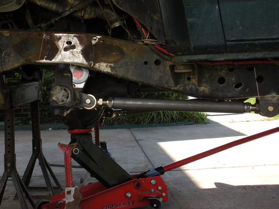
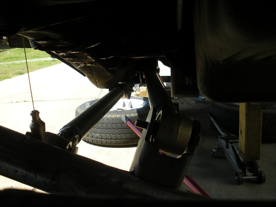
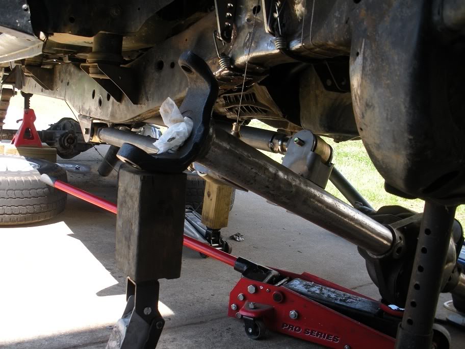
So with all the link mounts in place, it was time to fit all the bars and run some test flexes to look for any binding points or points where the axle or links would hit the frame.

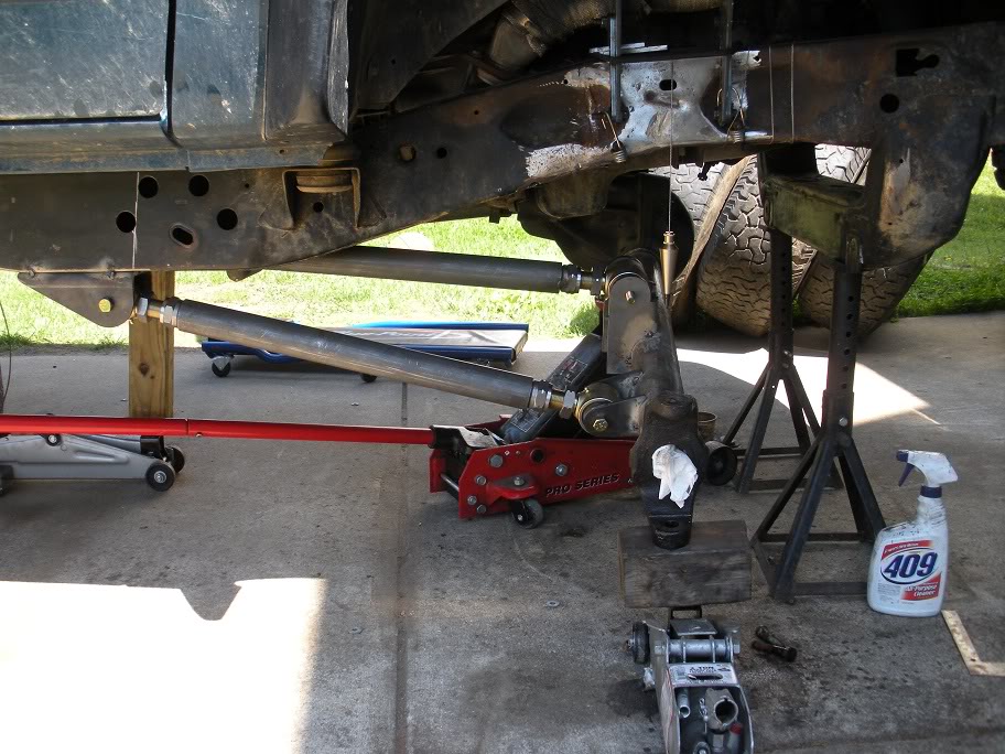
So with all the link mounts in place, it was time to fit all the bars and run some test flexes to look for any binding points or points where the axle or links would hit the frame.
Last edited by 95_318SLT; 05-11-2010 at 07:42 PM.
#18
04-30-2010, 09:57 PM
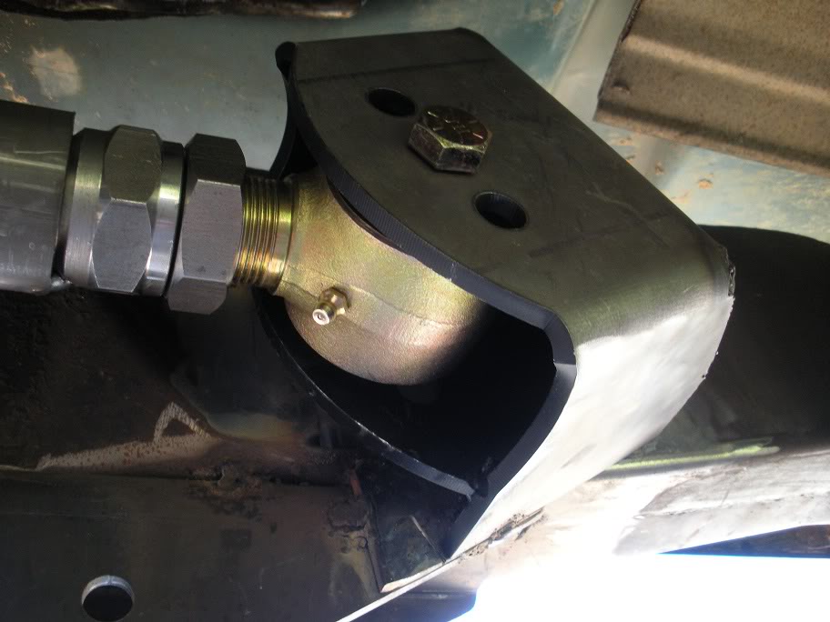
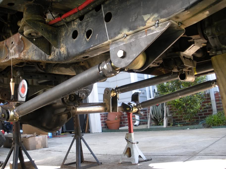
Now that I'm satisfied that the 3 link flexes like it should without running into anything, its time to line up the coil spring mounts.
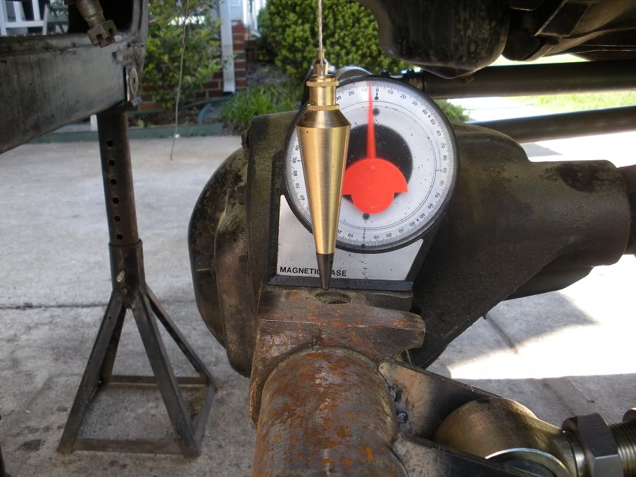
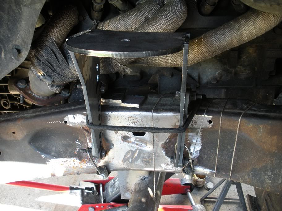
So I started by tacking the upper mounts together and strapping them to the frame to line them up and mark their location. I placed them using a plumb bob like most everything else with this project! (Like I said in the beginning, having the truck level is the best way to start!!)
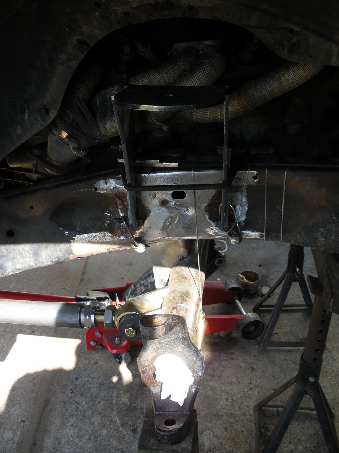
Axle flexed all the way up...
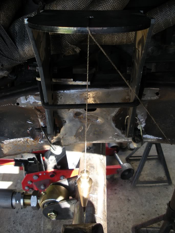
Axle sitting about at ride height...

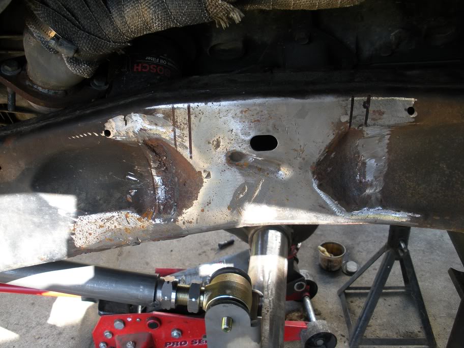
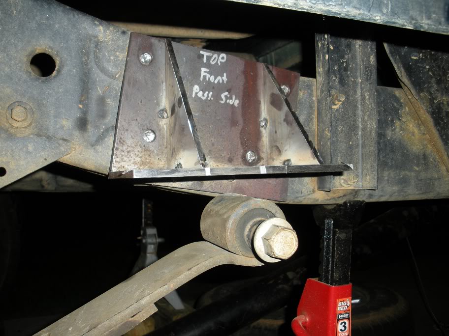
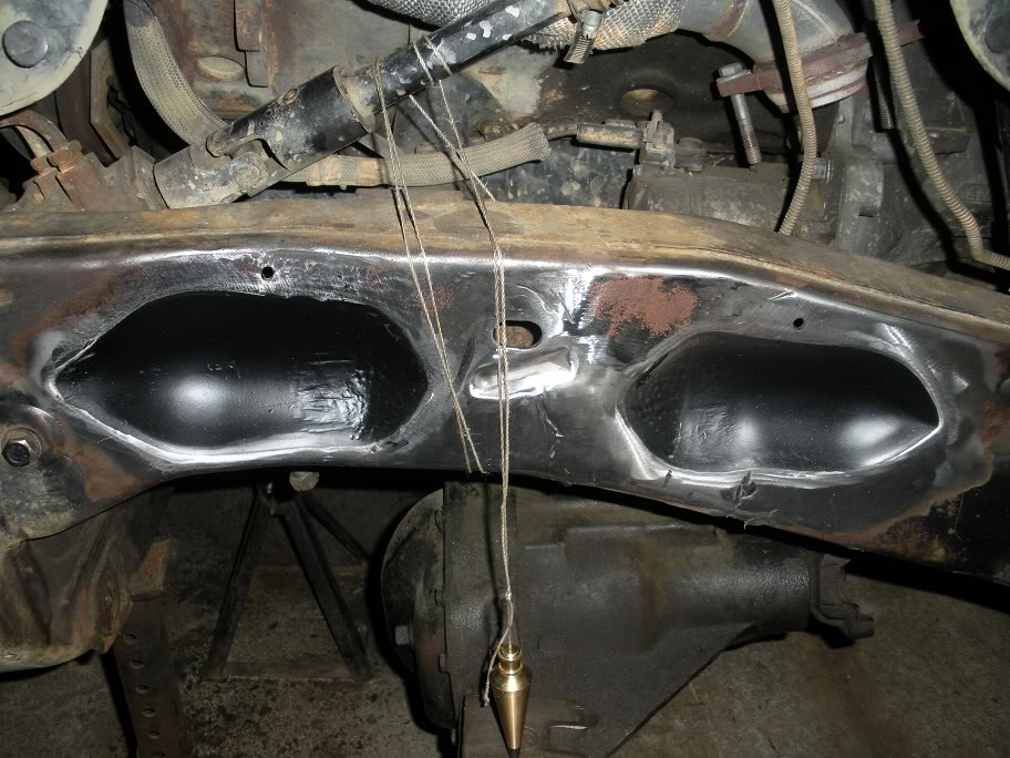
So you can see in the above pictures that the coil mounts will sit right over where the frame is rolled in for the upper control arm clearance. This means that before I continue, the frame needs to be flattened. I decided to cut out a piece of metal that will sit just far enough in and weld it in place that it will be flat when the welds are ground down. Here are my templates...
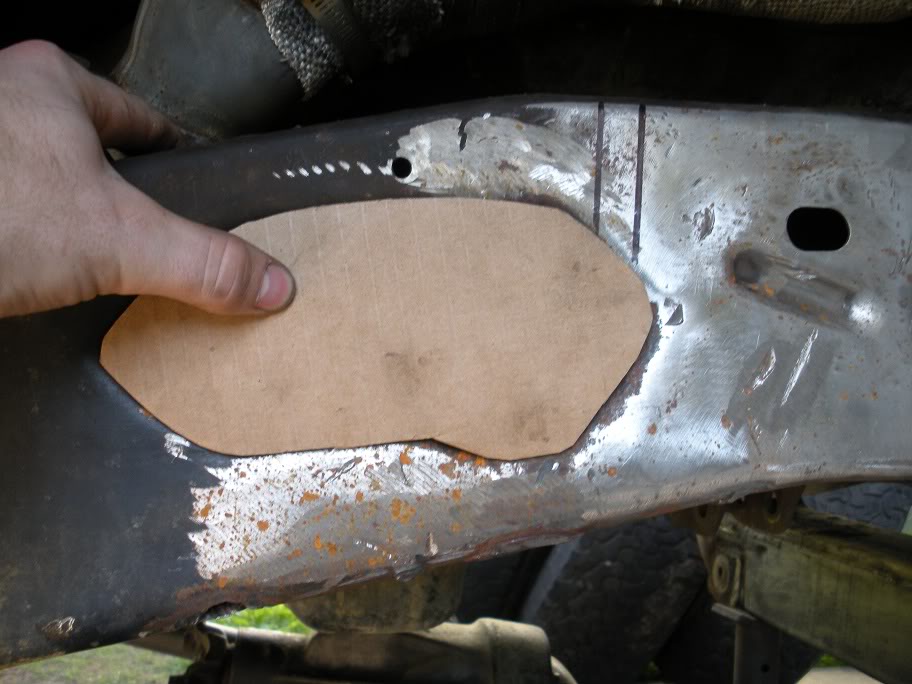
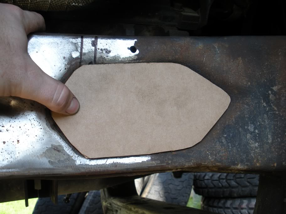
Now I just need to track down a .125"x4"x2' peice of plate steel and get to cutting and welding!
So I started by tacking the upper mounts together and strapping them to the frame to line them up and mark their location. I placed them using a plumb bob like most everything else with this project! (Like I said in the beginning, having the truck level is the best way to start!!)
Axle flexed all the way up...
Axle sitting about at ride height...
So you can see in the above pictures that the coil mounts will sit right over where the frame is rolled in for the upper control arm clearance. This means that before I continue, the frame needs to be flattened. I decided to cut out a piece of metal that will sit just far enough in and weld it in place that it will be flat when the welds are ground down. Here are my templates...
Now I just need to track down a .125"x4"x2' peice of plate steel and get to cutting and welding!
Last edited by 95_318SLT; 05-11-2010 at 07:53 PM.
#19
05-07-2010, 08:59 PM
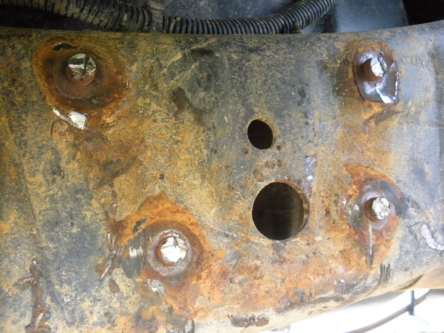
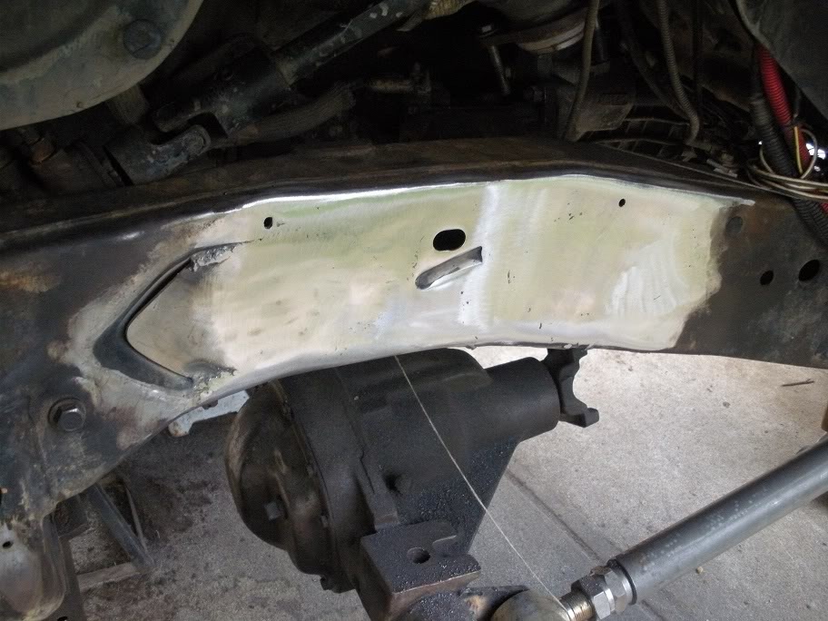
Well I got the steel plate I need and started cutting out the shapes. I had a heck of a bad week this past week which is why I haven't gotten much done, but I got started filling in the frame.
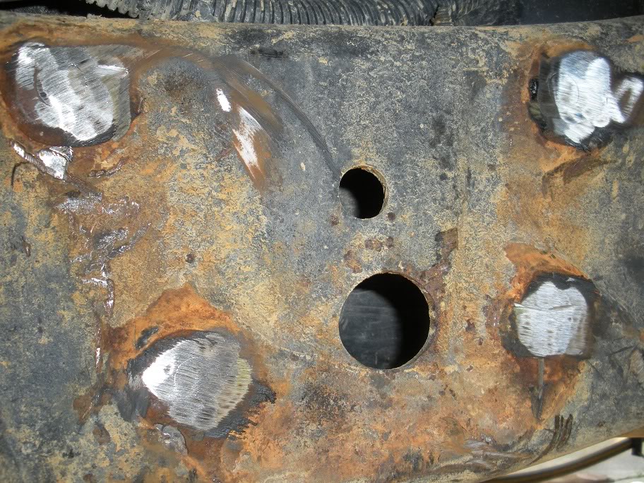
The first thing I did was finished cleaning out the rest of the factory mounts from the indentions and sprayed some paint in there to avoid future rust if moisture gets between my plate and the frame. Probably won't happen, just a precaution.
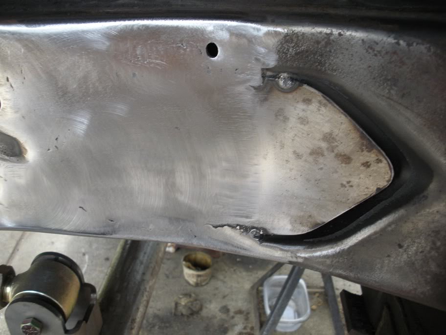
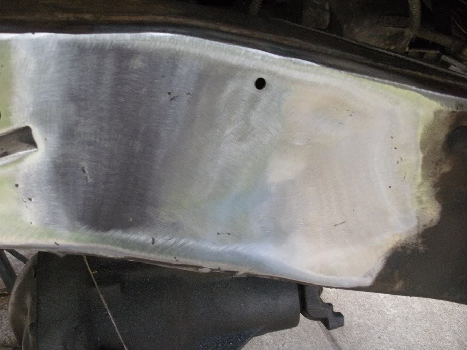
So here is the first plate. Still need to clean up the edges, but its about done.
The first thing I did was finished cleaning out the rest of the factory mounts from the indentions and sprayed some paint in there to avoid future rust if moisture gets between my plate and the frame. Probably won't happen, just a precaution.
So here is the first plate. Still need to clean up the edges, but its about done.
#20
05-10-2010, 06:56 PM
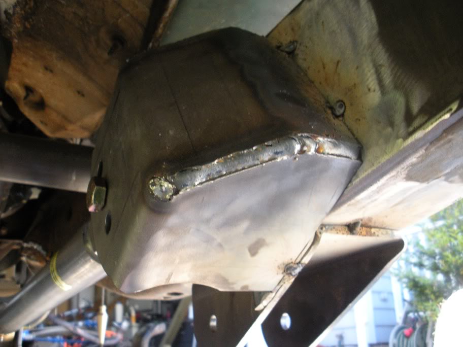
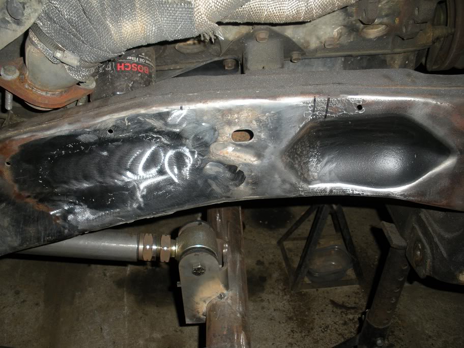
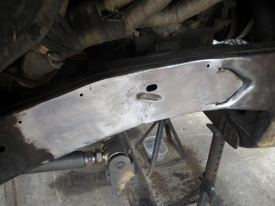
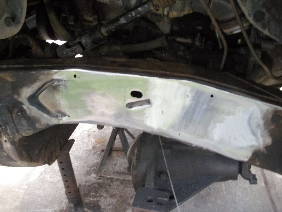
And here is the second plate...
As you can see, I still need to weld up the right side of the plate, but I need to wait for a bigger welder that can fill in the gap. Also, the only part of the frame I'm worried about being flat is what is already done... there won't be any mounts or brackets welded to that right side of the plate.
Also, as you can see, I didn't try to fill in the entire indention in the frame. The frame starts to roll outward where my welding stops, and since I'm not putting anything there, I'm not worried about making it "flat".
Here is a wider view of both sides...
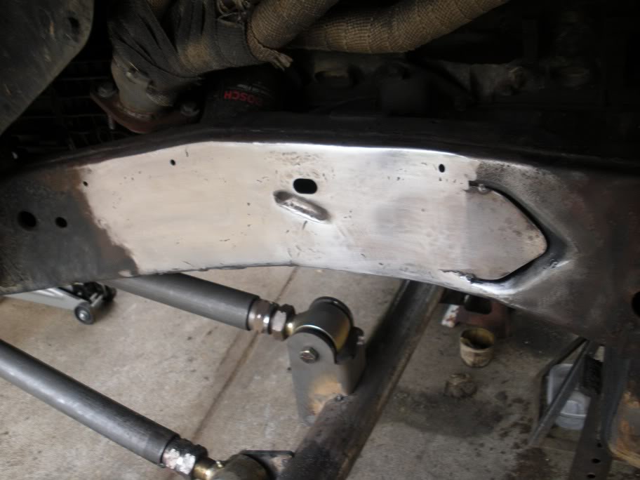
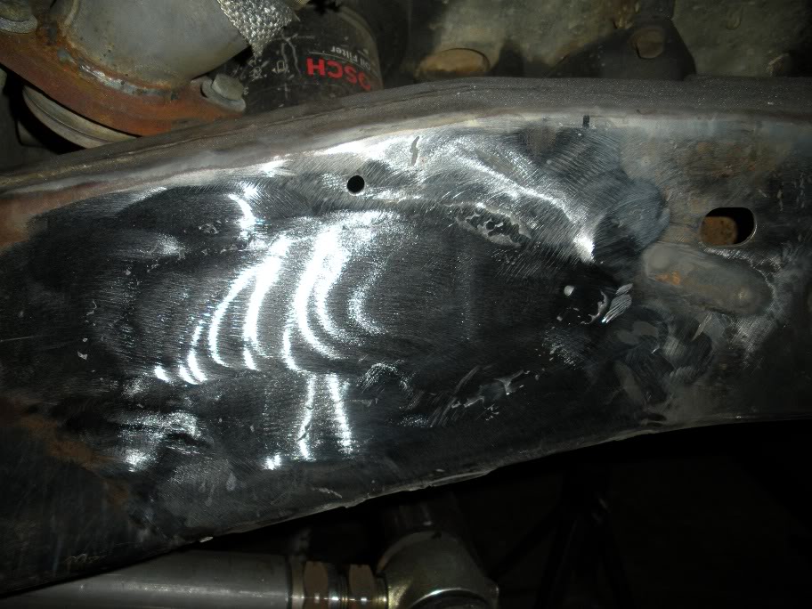
And here is the driver's side...

As you can see, I still need to weld up the right side of the plate, but I need to wait for a bigger welder that can fill in the gap. Also, the only part of the frame I'm worried about being flat is what is already done... there won't be any mounts or brackets welded to that right side of the plate.
Also, as you can see, I didn't try to fill in the entire indention in the frame. The frame starts to roll outward where my welding stops, and since I'm not putting anything there, I'm not worried about making it "flat".
Here is a wider view of both sides...
And here is the driver's side...
Last edited by 95_318SLT; 05-11-2010 at 07:55 PM.