
shortage in Dashboard lights
#21
 07-02-2013, 02:29 PM


#24
10-04-2013, 08:10 AM
#25
11-25-2013, 07:50 AM
Hello guys,
There is no shortage in Dashboard light , there is no fuse related problem, also spraying the back cluster's connectors with contact lube will do no good, there is no poor connection either.
The Dodge Caliber Instruments Cluster Light came from a thin EL (electroluminescent) foil that is right under the printed transparent plastic of your instruments.
This electroluminescent foil in terms of electronics is nothing but a capacitor and it have the property that when is connected to alternative voltage (between 40 and 114 Vrms) it emit light. Now, There is no AC 114 Vrms (volts root mean square) alternative voltage in your car so it need to be created by an inverter.
The fault part is the inverter situated on the board PCB. This inverter use a specialized IC which produce a maxim 300Vpp (peak to peak) under load at 250Hz with a wave shape that offer effective 114Vrms at maximum intensity.
Dodge Caliber instruments clusters light failure appear because this inverter is under dimensioned from the start , yes that's right a electronic design flaw. This can be cleared demonstrated (if there's still a need) by looking at parametric specification of the IC used at the core of the inverter. The H bridge of the IC can drive no more than 80nF of EL (electroluminescent) panel capacitance and the Caliber EL measured is between 90nF at 92F degree and 120nF at 70F degree, yes the capacitance of EL are inverse proportional with temperature.
One characteristic of EL panels are that at the same AC Voltage, once they aging it emit less light as a new one. To compensate this, the microprocessor of the board Freescale MC9S12, counts the time EL is on and drive the inverter to produce more voltage as the EL is aging so the stress of the inverter is greater as the EL is used more.
So no wonder that this instruments lights are dying like files in autumn all around the world, and a new one sooner or later will have the same fate.
I bought a used Dodge Caliber Instrument Cluster from ebay, where there's tons of them, (I wonder why) and it worked exactly six months before fail in glory as original one.
So I decide to play this game no more and build my own inverter that fits just fine and is capable of driving three EL cluster like caliber's ~450nF !!! in total, maintaining all functionality as original one, dimming , intensity per dimming steps .. everything.
#26
11-29-2013, 07:33 PM
Hi Fox,
Unfortunately is impossible to modify the stock inverter as there is no space available on the dashboard PCB. Moreover, the defective part is the Inverter driver IC itself as I explained in details in my first post.
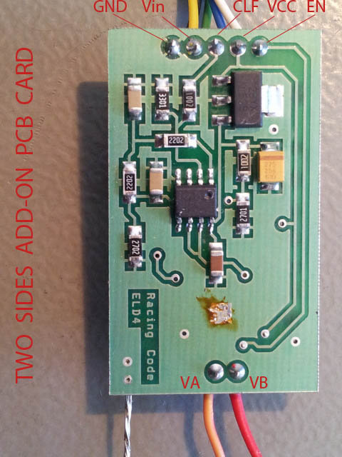
My fix was to build my own inverter on a new add on card and connect it to the dashboard PCB with seven wires, as in pictures.


There is not so difficult to solder the seven wires from the add-on card to the PCB even for inexperienced person, as the joint points are relatively large.
Unfortunately is impossible to modify the stock inverter as there is no space available on the dashboard PCB. Moreover, the defective part is the Inverter driver IC itself as I explained in details in my first post.
My fix was to build my own inverter on a new add on card and connect it to the dashboard PCB with seven wires, as in pictures.


There is not so difficult to solder the seven wires from the add-on card to the PCB even for inexperienced person, as the joint points are relatively large.
Last edited by Moc; 11-29-2013 at 07:37 PM.
#27
12-02-2013, 12:31 PM
Hello Moc!
Hey, you made really a great job. How can i get the same Inverter? Where can i buy the Inverter PCB card that you used? Seems to be the most interesting solution for me too!
Rudi
Hey, you made really a great job. How can i get the same Inverter? Where can i buy the Inverter PCB card that you used? Seems to be the most interesting solution for me too!
Rudi
Hi Fox,
Unfortunately is impossible to modify the stock inverter as there is no space available on the dashboard PCB. Moreover, the defective part is the Inverter driver IC itself as I explained in details in my first post.
My fix was to build my own inverter on a new add on card and connect it to the dashboard PCB with seven wires, as in pictures.

There is not so difficult to solder the seven wires from the add-on card to the PCB even for inexperienced person, as the joint points are relatively large.
Unfortunately is impossible to modify the stock inverter as there is no space available on the dashboard PCB. Moreover, the defective part is the Inverter driver IC itself as I explained in details in my first post.
My fix was to build my own inverter on a new add on card and connect it to the dashboard PCB with seven wires, as in pictures.
There is not so difficult to solder the seven wires from the add-on card to the PCB even for inexperienced person, as the joint points are relatively large.
#28
12-06-2013, 08:17 AM
Hello Rudi
Although I work in electronics R&D automotive related company I build this inverter add-on card for fixing my car and for some friends and local clients with Calibers and Chrysler Sebring dashboard light problem. Didn't thought to put it on eBay or something like this , but I might be going to mass-producting this add-on inverter cards as the time go by more dashboards will fail allover the world.
Although I work in electronics R&D automotive related company I build this inverter add-on card for fixing my car and for some friends and local clients with Calibers and Chrysler Sebring dashboard light problem. Didn't thought to put it on eBay or something like this , but I might be going to mass-producting this add-on inverter cards as the time go by more dashboards will fail allover the world.
#30
12-09-2013, 10:21 AM
At least, let us know if you're going to make them shortly!
Thanks!