1st Gen Dakota Tech 1987 - 1996 Dodge Dakota Tech - The ultimate forum for technical help on the 1st Gen Dakota.

Remote Door Locks

Thread Tools
 
Search this Thread
 
Old Jan 7, 2011 | 11:43 AM
  #11  
bertbart's Avatar
bertbart
Thread Starter
|
Registered User
Joined: Jan 2011
Posts: 11
Likes: 0
Default ok ic

should i do this at the passenger door that is were the same color wires are that are at the motors do i use thouse wires sorry this has been a pain every thing on line says pink and violet and orange and violet yet the motor wires are pink and black and orange and black
 
Reply
Old Jan 7, 2011 | 03:51 PM
  #12  
festerw's Avatar
festerw
Veteran
Joined: Jul 2009
Posts: 447
Likes: 0
Default

Don't look for the wires in the door itself you'll want the wires under the dash near the drivers kick panel.

You'll see where to pick them up in this thread
https://dodgeforum.com/forum/1st-gen...ess-entry.html
 
Reply
Old Jan 7, 2011 | 04:59 PM
  #13  
bertbart's Avatar
bertbart
Thread Starter
|
Registered User
Joined: Jan 2011
Posts: 11
Likes: 0
Default ok

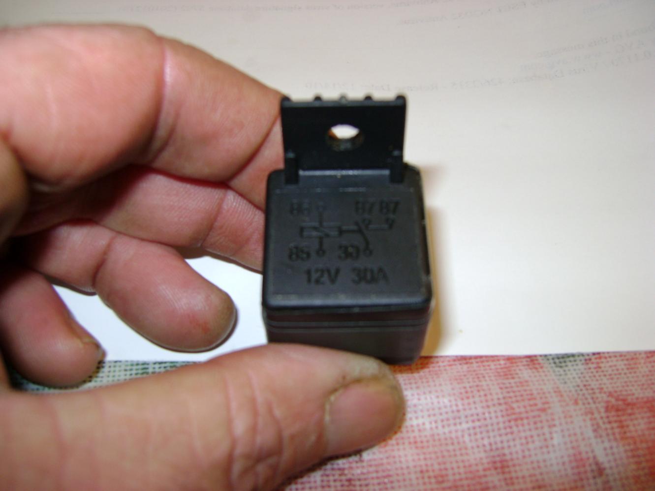
I thank you big time but i have tryed that pink ad violet one switch side to 87a and the other side of the cut pink and violet to 30 87 and 86 12 volts fuesd and85 to remote should i be useing the pink and black and orange and black thanks for the pics but i must be stupid cause i tryed that the side i think is motor reads power from passenger switch when i try it so is it the other wires then
 
Reply
Old Jan 8, 2011 | 02:05 PM
  #14  
bertbart's Avatar
bertbart
Thread Starter
|
Registered User
Joined: Jan 2011
Posts: 11
Likes: 0
Default ok

What am i doing wrong pink and violet orange and violet or the motor wires pink and black orange and black
 
Reply
Old Jan 8, 2011 | 07:02 PM
  #15  
festerw's Avatar
festerw
Veteran
Joined: Jul 2009
Posts: 447
Likes: 0
Default

Double check the wiring and the manual for the lock module make sure you don't need to change anything on the module itself. Try calling their tech support to find out if it's wired properly.
 
Reply
Old Jan 8, 2011 | 09:54 PM
  #16  
bertbart's Avatar
bertbart
Thread Starter
|
Registered User
Joined: Jan 2011
Posts: 11
Likes: 0
Default ya

they say 2 relays nice ah
 
Reply
Old Jan 9, 2011 | 12:42 PM
  #17  
bertbart's Avatar
bertbart
Thread Starter
|
Registered User
Joined: Jan 2011
Posts: 11
Likes: 0
Default ok here is a pic of my relays

Remote Door Locks-dsc00145.jpg

Remote Door Locks-dsc00153.jpg
Ok do i cut just the orange and violet and pink and violet or do i cut the motor wires to
i no if i cut the pink and violet on the drivers side that side quits working and pass side one way
but the same goes on the pass side if i cut pink and violet there that side quits and the drivers side one way

The wires are as follows orange and violet pink and violet red 12 v center and two black wires on the drivers side switch
pass side is orange and violet pink and violet red center 12v orange and black pink ad black
 

Last edited by bertbart; Jan 9, 2011 at 02:46 PM.
Reply
Old Jan 10, 2011 | 07:02 AM
  #18  
festerw's Avatar
festerw
Veteran
Joined: Jul 2009
Posts: 447
Likes: 0
Default

Find the pink and orange in the kick panel, cut them and wire it up like the diagram in the pdf I posted.
 
Reply
Old Jan 10, 2011 | 07:14 AM
  #19  
bertbart's Avatar
bertbart
Thread Starter
|
Registered User
Joined: Jan 2011
Posts: 11
Likes: 0
Default ok

do i add any othr wires pink and violet orange and violet i have done that
but i blow fuses what does it mean motor side the other side reads 12v if i use the pass switch
 
Reply
Old Jan 26, 2011 | 10:57 AM
  #20  
thomason's Avatar
thomason
Registered User
Joined: Jan 2011
Posts: 2
Likes: 0
Default

Thanks for the complete information. it is helpful for every one who is in need of the information. but i am so sorry have doubts on the diagram which is posted.


Last edited by HammerZ71; Jan 28, 2011 at 07:41 AM. Reason: advertising
Reply


All times are GMT -4. The time now is 08:11 PM.