

My Official Solid Axle Swap Thread (The Project Writeup)
#11
 05-28-2011, 01:28 PM

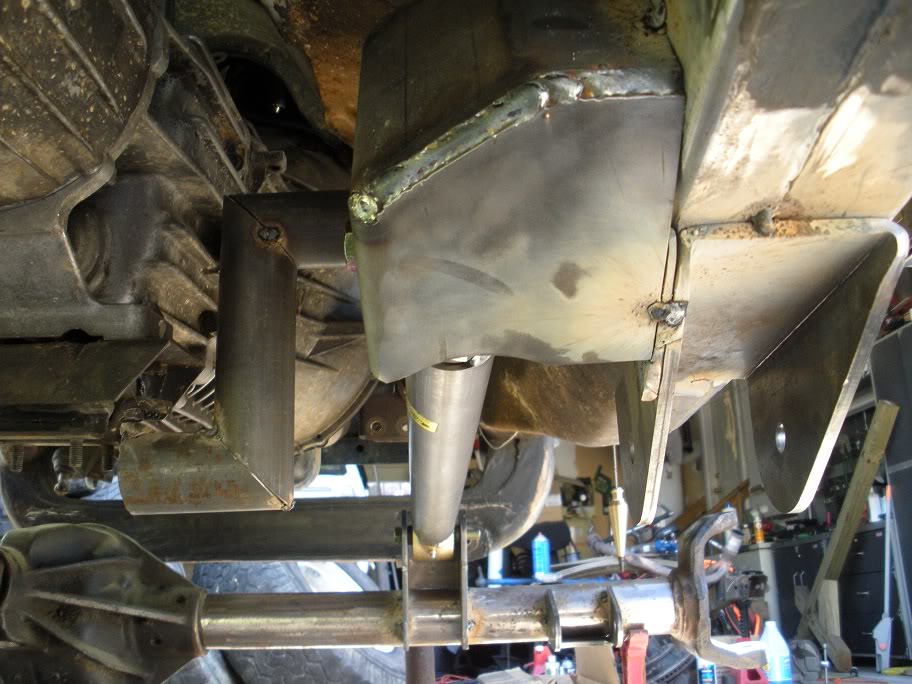
And once that one was placed, I used a johnny joint and the remaining tube to line up the upper link axle mount and tacked it in place...
Then I welded the spacer on, welded the upper link frame mount together and tacked it in place...
After taking measurements between the mounts and cut the upper link tube and fit it...

Then I welded the spacer on, welded the upper link frame mount together and tacked it in place...
After taking measurements between the mounts and cut the upper link tube and fit it...
#12
05-28-2011, 01:29 PM
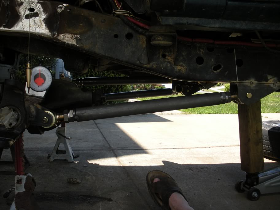
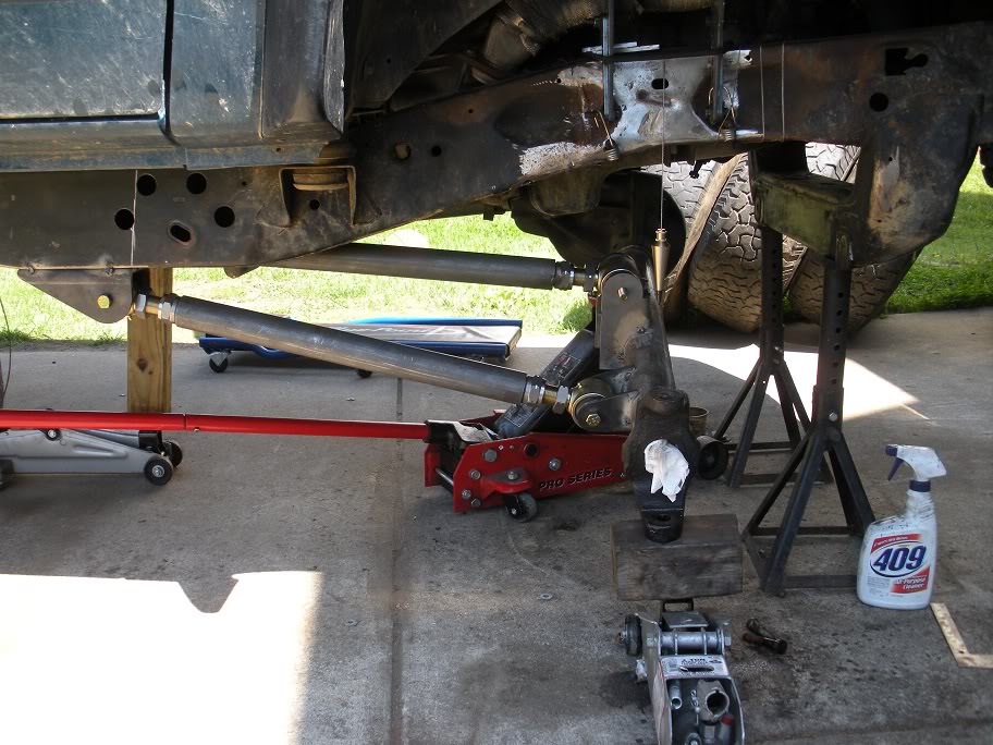
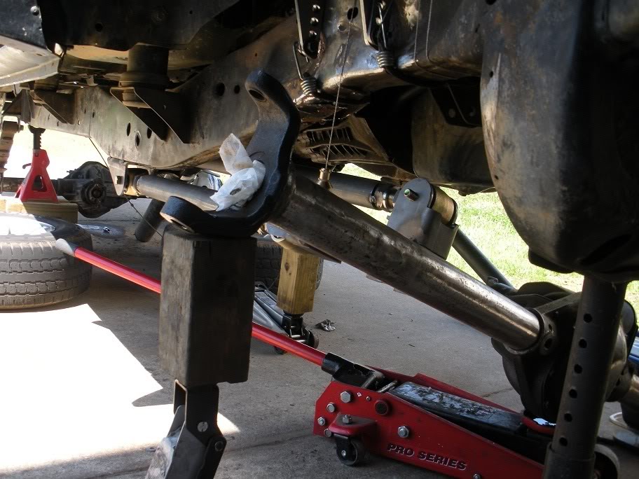
So with all the link mounts in place, it was time to fit all the bars and run some test flexes to look for any binding points or points where the axle or links would hit the frame.

#13
05-28-2011, 01:30 PM
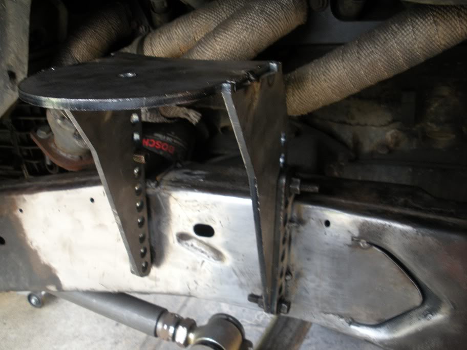
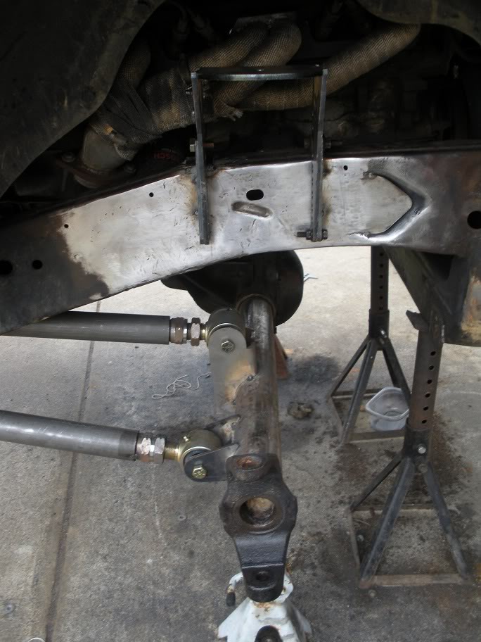
Now that I'm satisfied that the 3 link flexes like it should without running into anything, its time to line up the coil spring mounts.
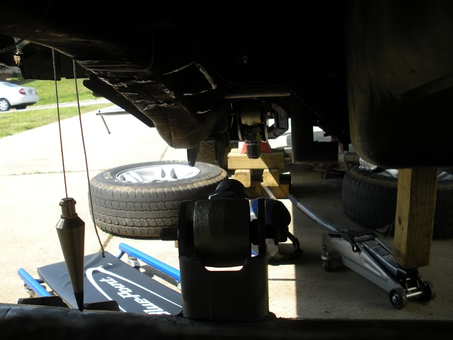
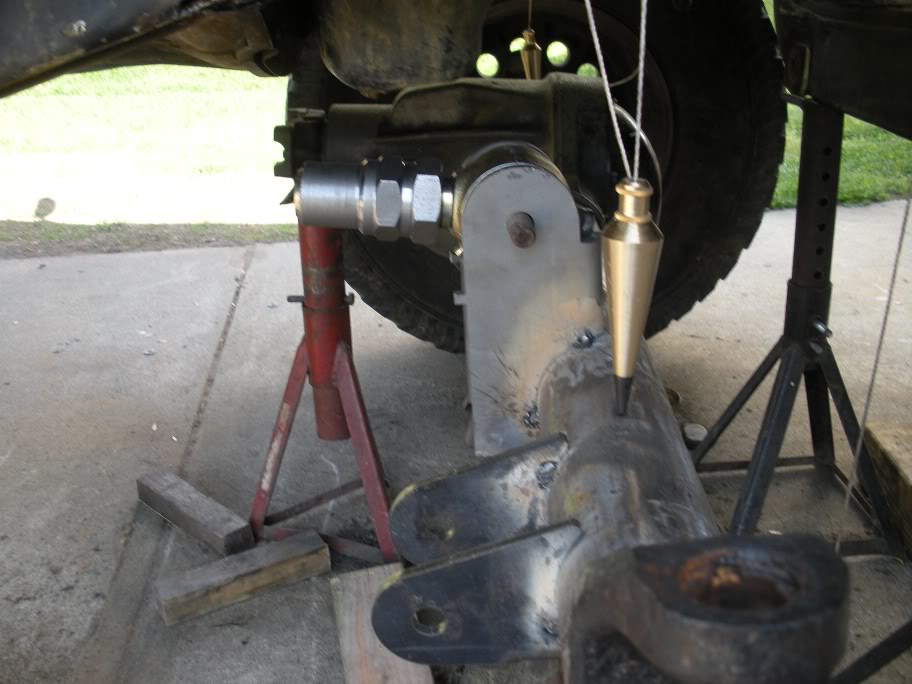
So I started by tacking the upper mounts together and strapping them to the frame to line them up and mark their location. I placed them using a plumb bob like most everything else with this project! (Like I said in the beginning, having the truck level is the best way to start!!)
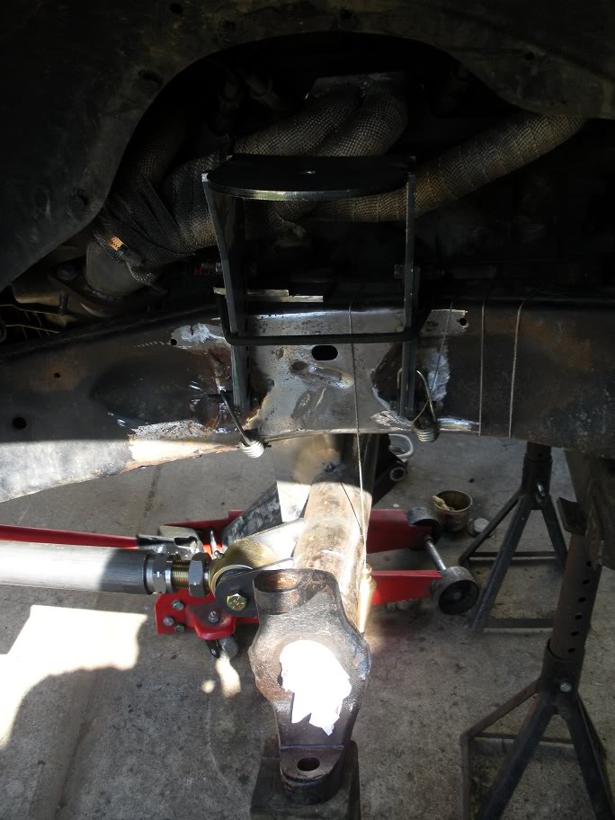
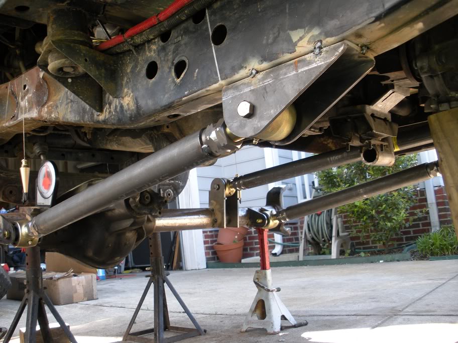
Axle flexed all the way up...
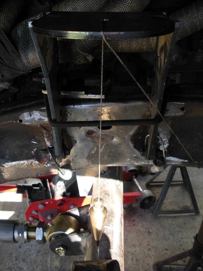
Axle sitting about at ride height...
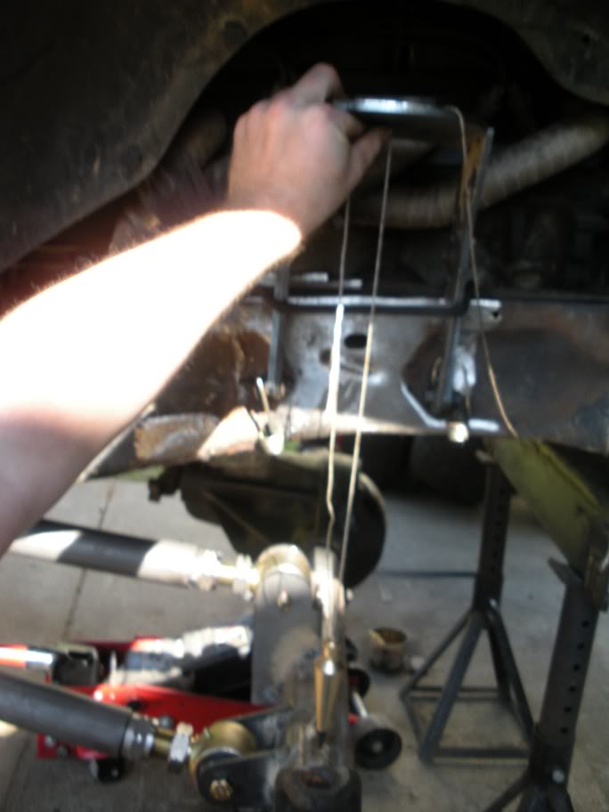

So you can see in the above pictures that the coil mounts will sit right over where the frame is rolled in for the upper control arm clearance. This means that before I continue, the frame needs to be flattened. I decided to cut out a piece of metal that will sit just far enough in and weld it in place that it will be flat when the welds are ground down. Here are my templates...

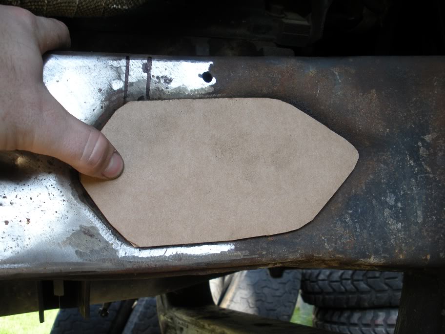
Now I just need to track down a .125"x4"x2' peice of plate steel and get to cutting and welding!
So I started by tacking the upper mounts together and strapping them to the frame to line them up and mark their location. I placed them using a plumb bob like most everything else with this project! (Like I said in the beginning, having the truck level is the best way to start!!)
Axle flexed all the way up...
Axle sitting about at ride height...
So you can see in the above pictures that the coil mounts will sit right over where the frame is rolled in for the upper control arm clearance. This means that before I continue, the frame needs to be flattened. I decided to cut out a piece of metal that will sit just far enough in and weld it in place that it will be flat when the welds are ground down. Here are my templates...
Now I just need to track down a .125"x4"x2' peice of plate steel and get to cutting and welding!
#14
05-28-2011, 01:30 PM
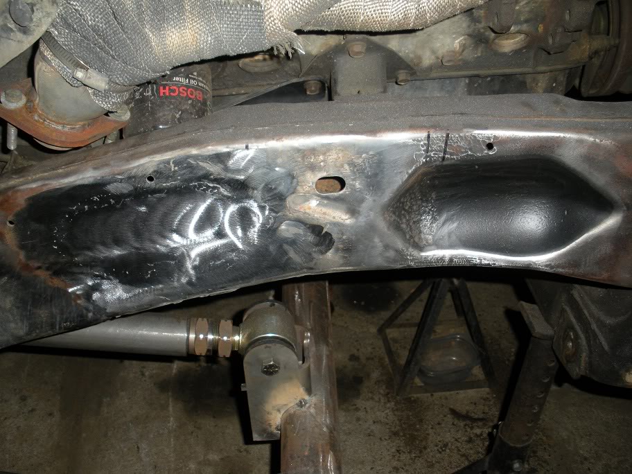
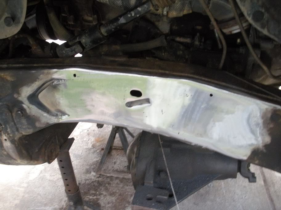
Well I got the steel plate I need and started cutting out the shapes. I had a heck of a bad week this past week which is why I haven't gotten much done, but I got started filling in the frame.
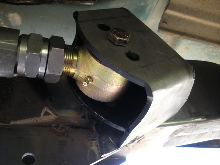
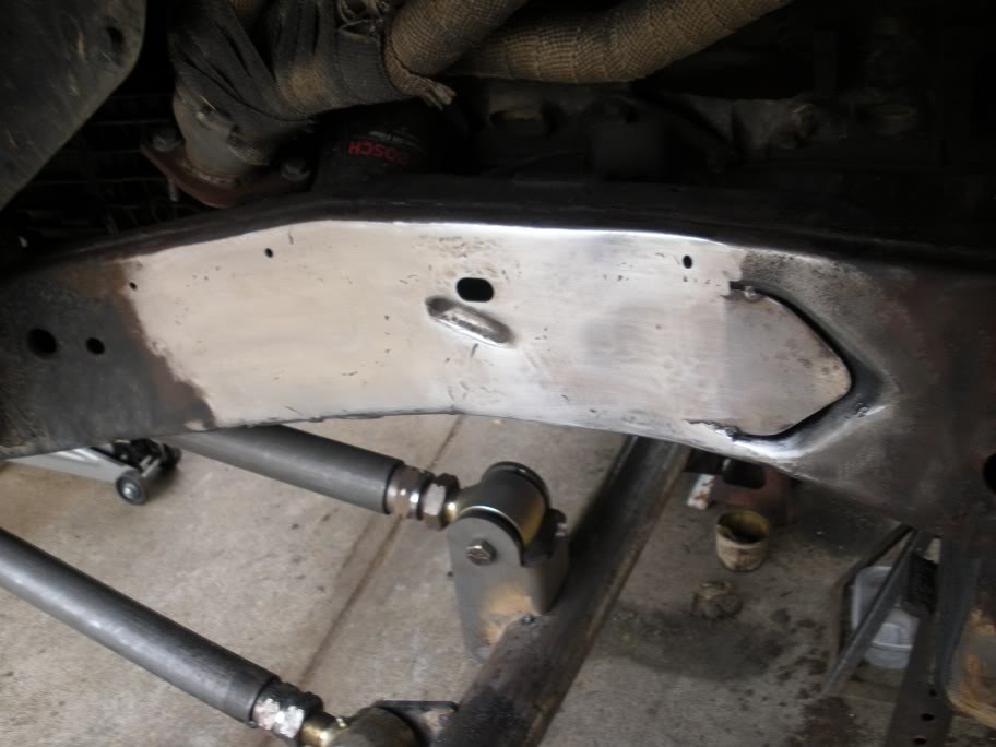
The first thing I did was finished cleaning out the rest of the factory mounts from the indentions and sprayed some paint in there to avoid future rust if moisture gets between my plate and the frame. Probably won't happen, just a precaution.

So here is the first plate. Still need to clean up the edges, but its about done.
The first thing I did was finished cleaning out the rest of the factory mounts from the indentions and sprayed some paint in there to avoid future rust if moisture gets between my plate and the frame. Probably won't happen, just a precaution.
So here is the first plate. Still need to clean up the edges, but its about done.
#15
05-28-2011, 01:33 PM
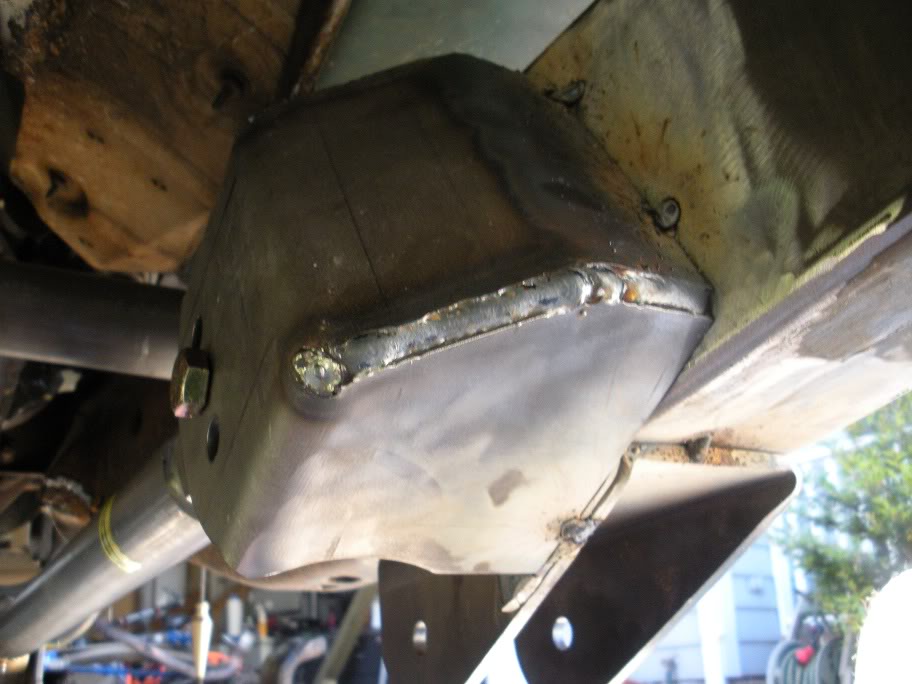
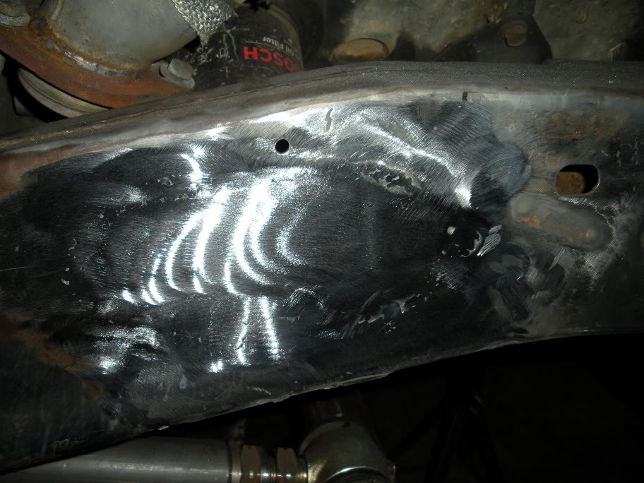
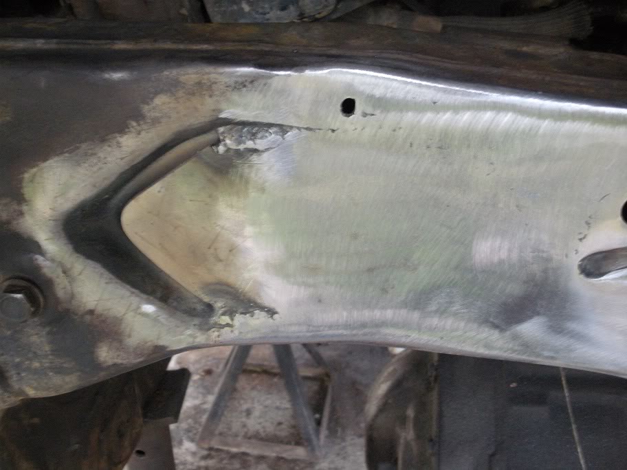
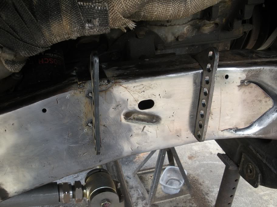
And here is the second plate...
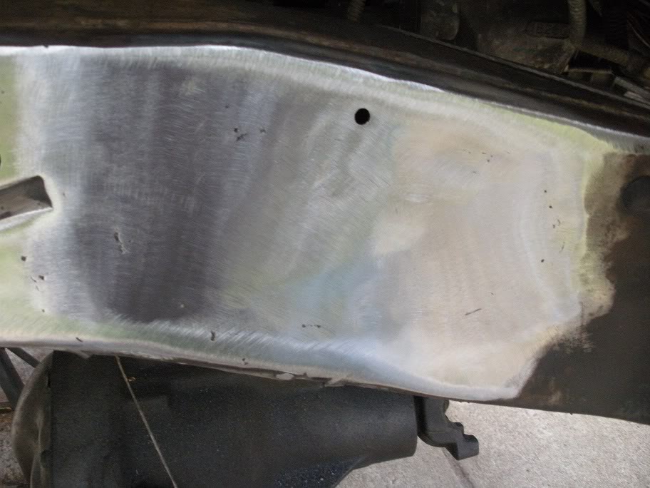
As you can see, I still need to weld up the right side of the plate, but I need to wait for a bigger welder that can fill in the gap. Also, the only part of the frame I'm worried about being flat is what is already done... there won't be any mounts or brackets welded to that right side of the plate.
Also, as you can see, I didn't try to fill in the entire indention in the frame. The frame starts to roll outward where my welding stops, and since I'm not putting anything there, I'm not worried about making it "flat".
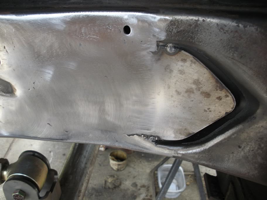
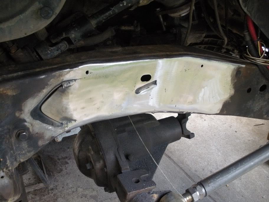
Here is a wider view of both sides...
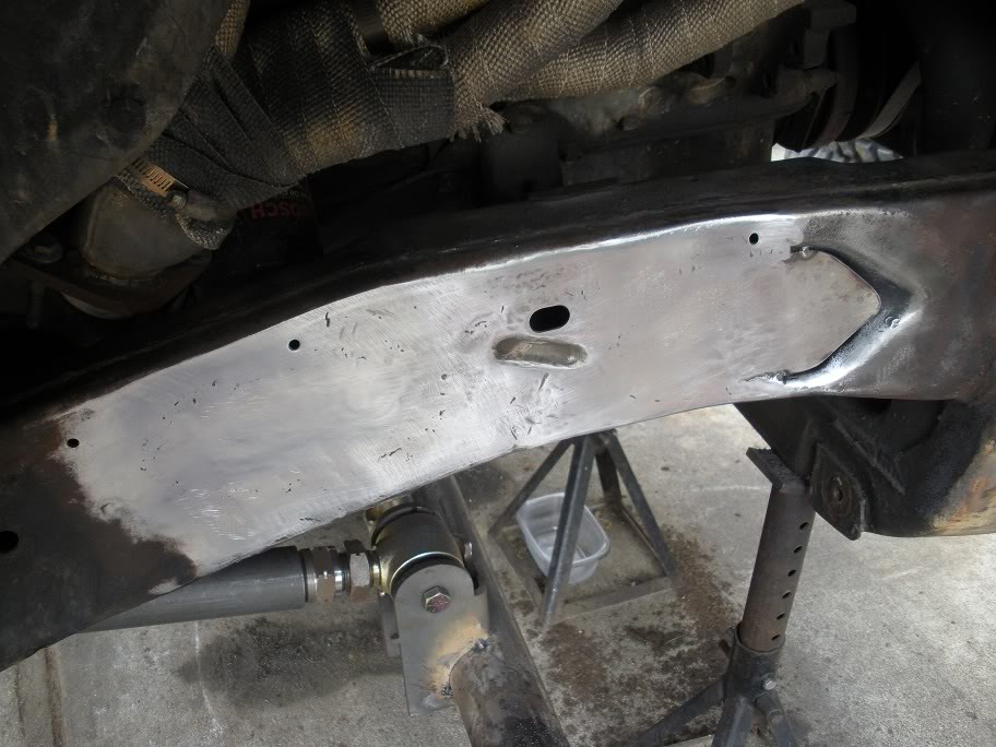
And here is the driver's side...
As you can see, I still need to weld up the right side of the plate, but I need to wait for a bigger welder that can fill in the gap. Also, the only part of the frame I'm worried about being flat is what is already done... there won't be any mounts or brackets welded to that right side of the plate.
Also, as you can see, I didn't try to fill in the entire indention in the frame. The frame starts to roll outward where my welding stops, and since I'm not putting anything there, I'm not worried about making it "flat".
Here is a wider view of both sides...
And here is the driver's side...
#16
05-28-2011, 01:35 PM
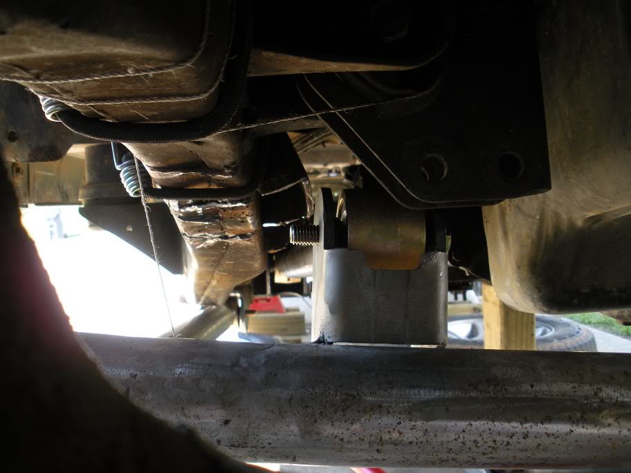
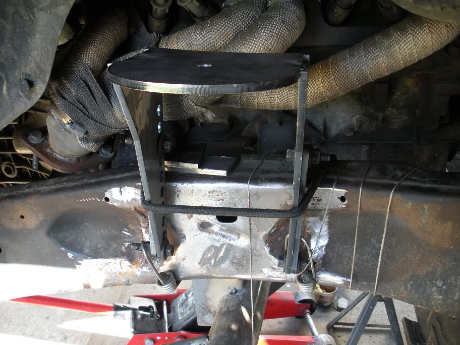
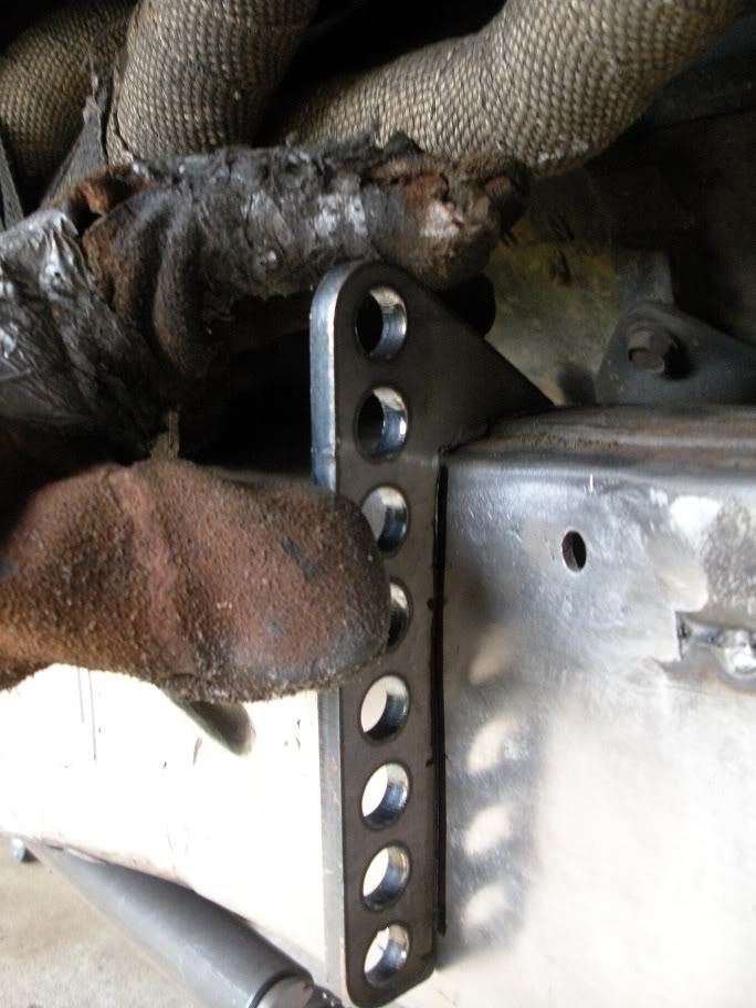
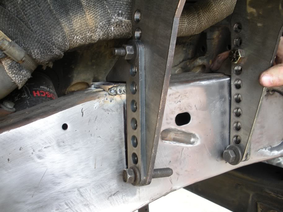
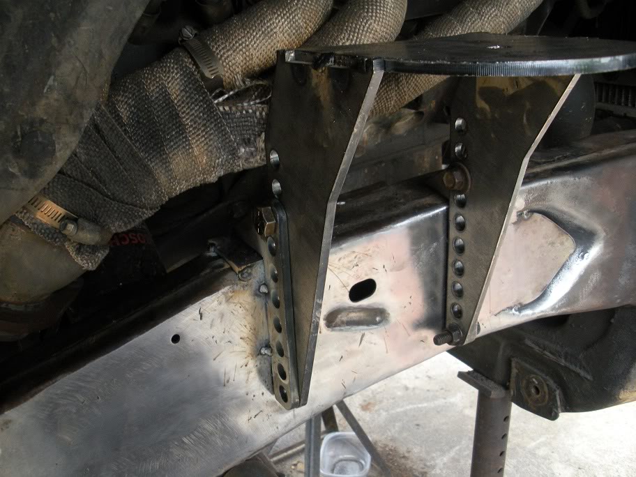
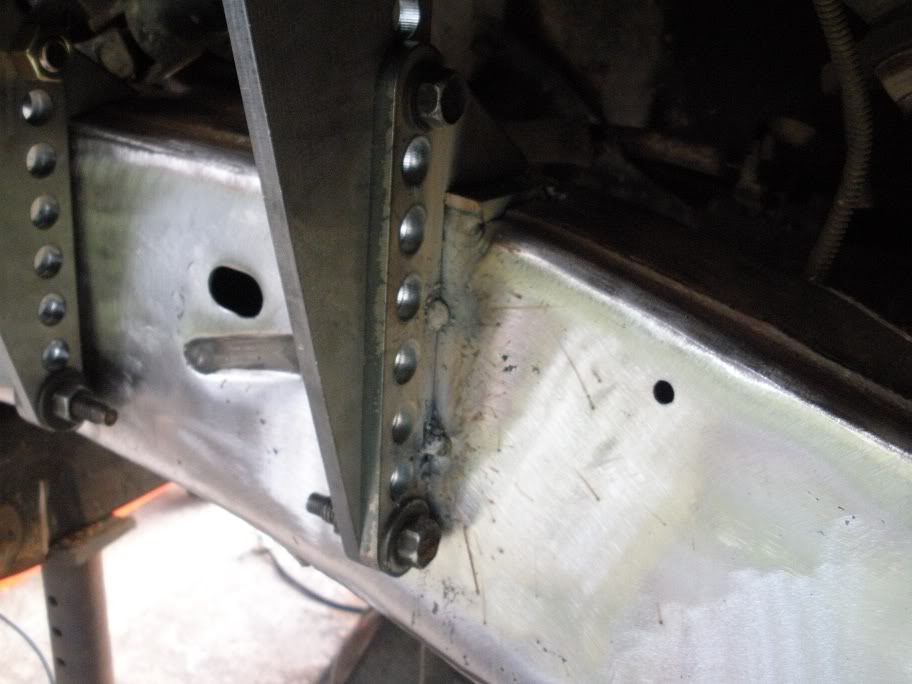
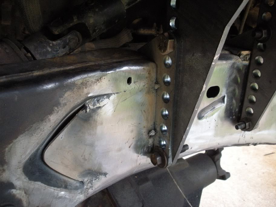
So now that the frame has been "flattened", its finally time to mount the coil spring towers. I started by strapping them to the frame to see how flat and level they would sit...
As you can see, the rear rail is 1/2 low of the front rail. I had two ways to deal with this... put a 1/2 inch spacer on the rear rail, or put a 1/4 inch spacer on the rear rail and cut 1/4 inch off the front rail. As you can see in the below picture, the top of the frame is not flat, so the rail needs to be trimmed anyway, so I decided to cut 1/4 inch off the front rail and put a 1/4 inch spacer on the rear rail.
After trimming...
So I did another test fit after getting the spacer in and trimming the rails...
And I was satisfied with the fit, so I tacked it on the frame.
The other side needs to be done the same way, and measured out from some point on the frame thats the same on both sides to make sure they are equal.
Here is the other side...
As you can see, these are adjustable coil towers... so once the rails are welded onto the frame, the towers can be mounted at whatever height is needed!
#17
05-28-2011, 01:35 PM
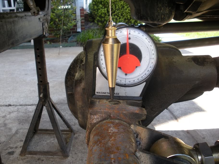
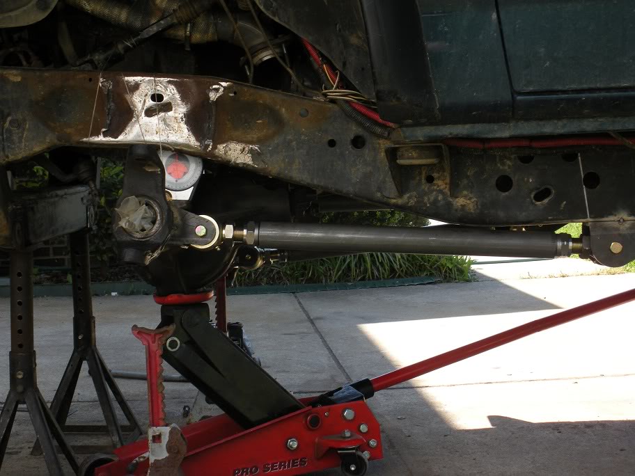
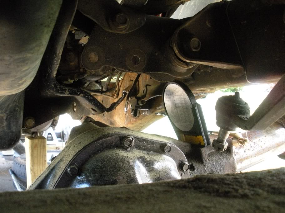
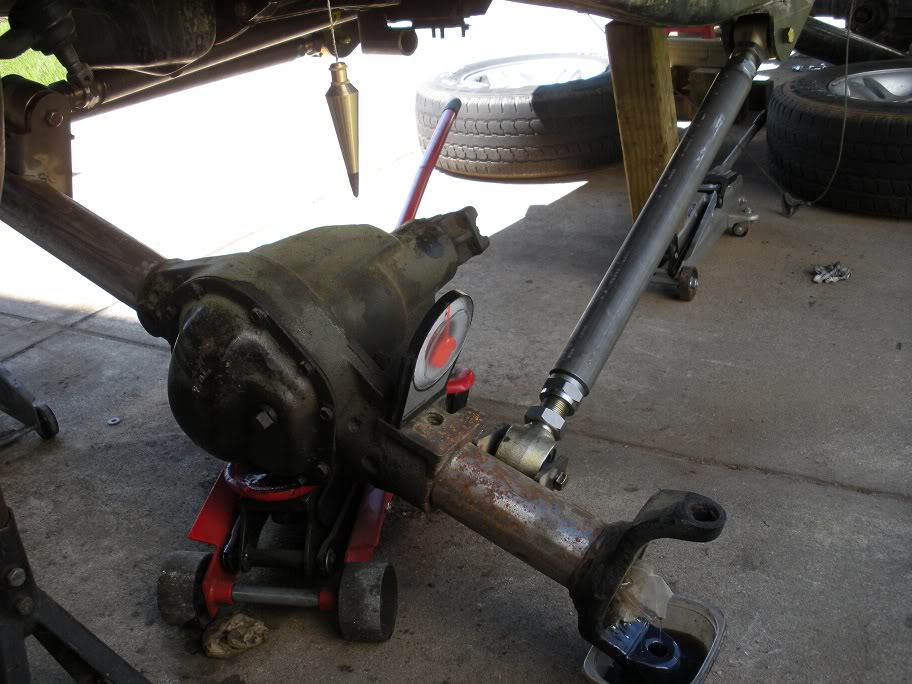
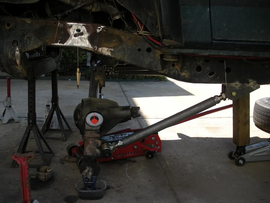
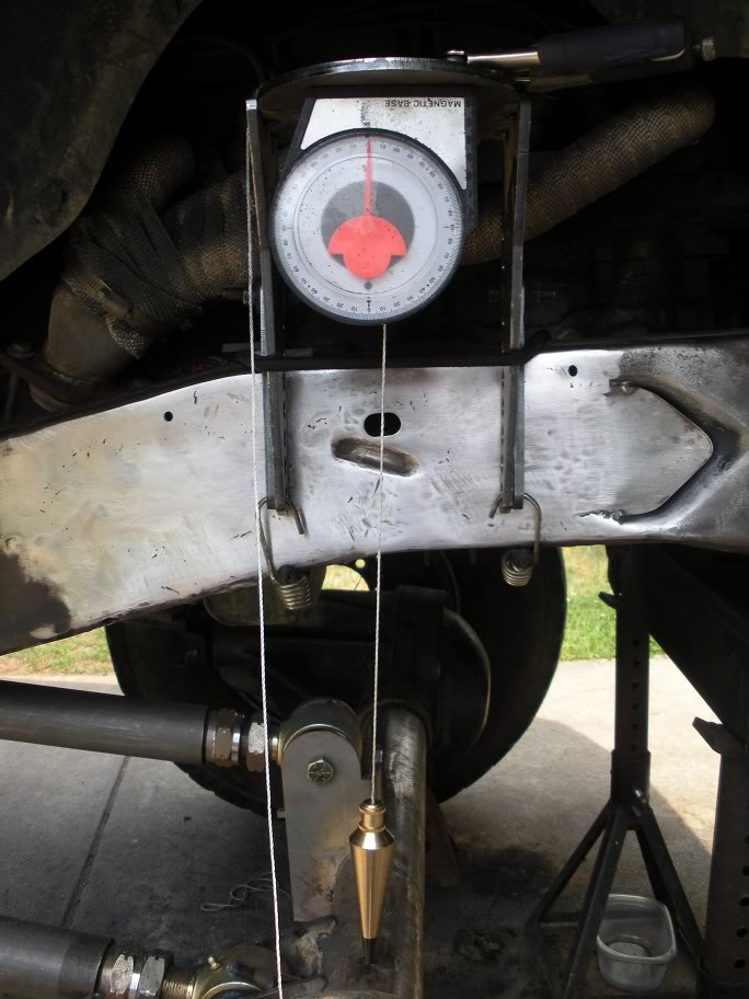
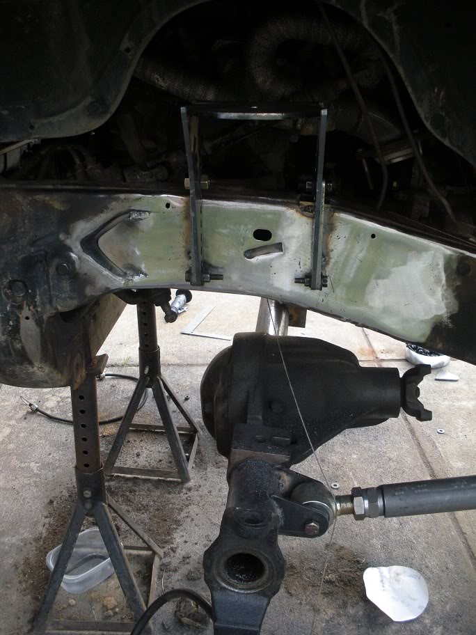
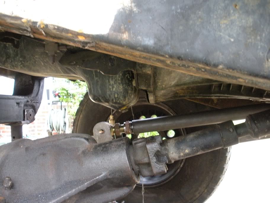
So now that the upper coil towers are mounted, the lower coil buckets need to be mounted. But, before they can be mounted, the pinion and castor angles need to be figured out and set up. If these aren't taken care of first, you could end up with the coil buckets sitting at odd angles later!
On a double cardan driveshaft, the pinion needs to be angled inline, or parallel (0 degrees) to the driveshaft. This is because the non-constant velocity rotational tendancies of of u-joint driveshafts are taken care of my the double-cardan joint and are not transferred through the entire driveshaft (if this statement makes no sense to you, you should do extensive research on driveline angles before attempting a project like this). The desired castor angle for a dana 44 solid front axle is -5-7 degrees, so with the pinion properly angled, the inner knuckle C's needs to be rotated to the desired castor angle.
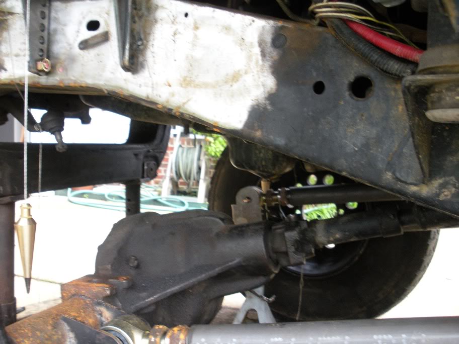
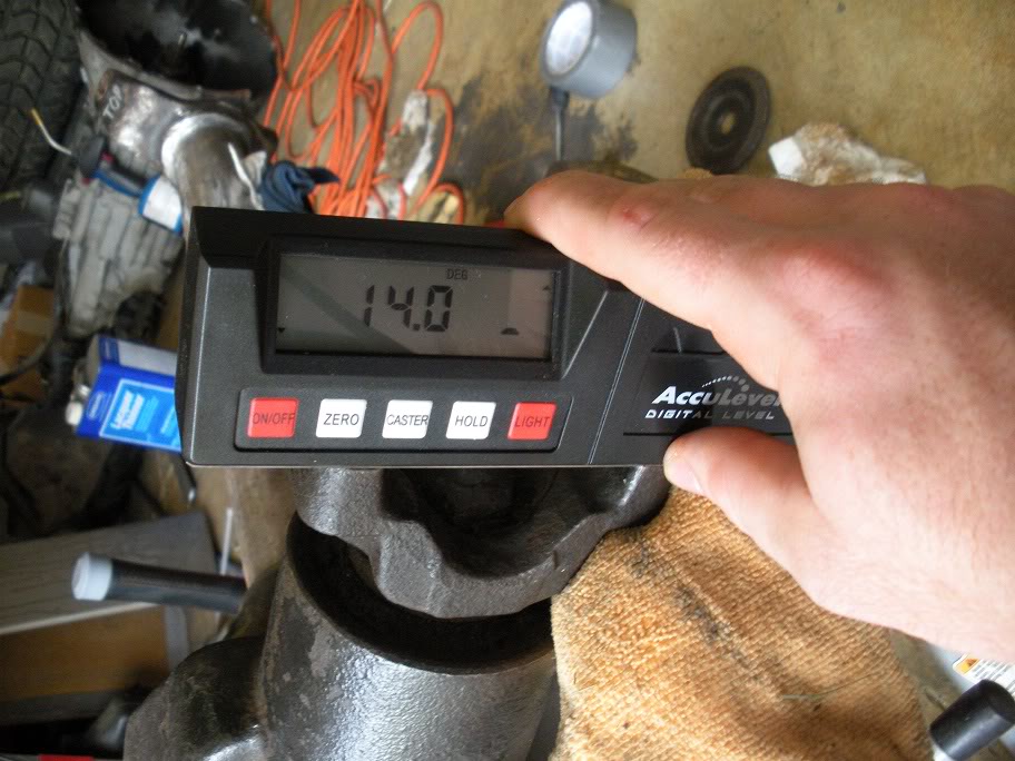
So I started by measuring out the axle to place it at ride height (or as close to ride height as I can estimate right now). I measured the rear axle sprung from centerline to the top of the wheel well and copied it on the front. Then I used my front driveshaft to eye the pinion angle. Because it's a double cardan driveshaft, and the pinion needs to be inline with the driveshaft, eyeing the pinion angle isn't hard. The pinion angle came out to be 14 degrees up.
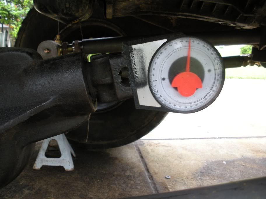
On a double cardan driveshaft, the pinion needs to be angled inline, or parallel (0 degrees) to the driveshaft. This is because the non-constant velocity rotational tendancies of of u-joint driveshafts are taken care of my the double-cardan joint and are not transferred through the entire driveshaft (if this statement makes no sense to you, you should do extensive research on driveline angles before attempting a project like this). The desired castor angle for a dana 44 solid front axle is -5-7 degrees, so with the pinion properly angled, the inner knuckle C's needs to be rotated to the desired castor angle.
So I started by measuring out the axle to place it at ride height (or as close to ride height as I can estimate right now). I measured the rear axle sprung from centerline to the top of the wheel well and copied it on the front. Then I used my front driveshaft to eye the pinion angle. Because it's a double cardan driveshaft, and the pinion needs to be inline with the driveshaft, eyeing the pinion angle isn't hard. The pinion angle came out to be 14 degrees up.
#18
05-28-2011, 01:37 PM
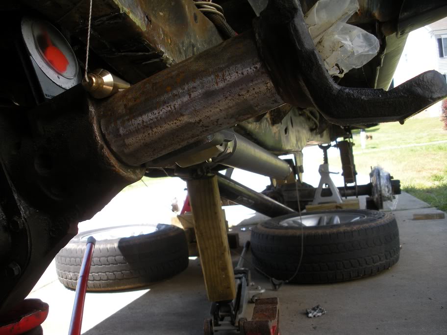
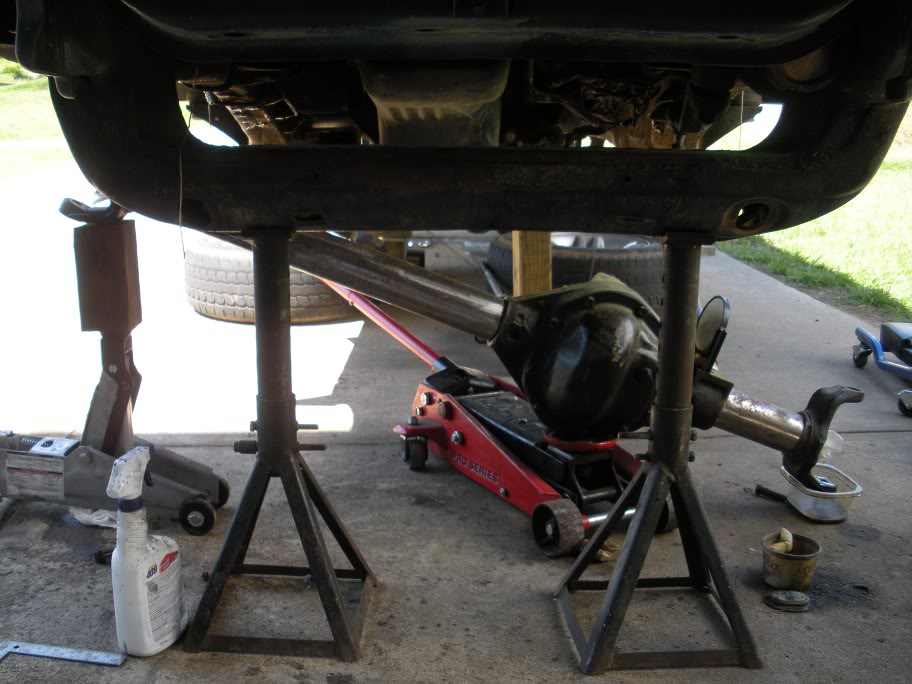
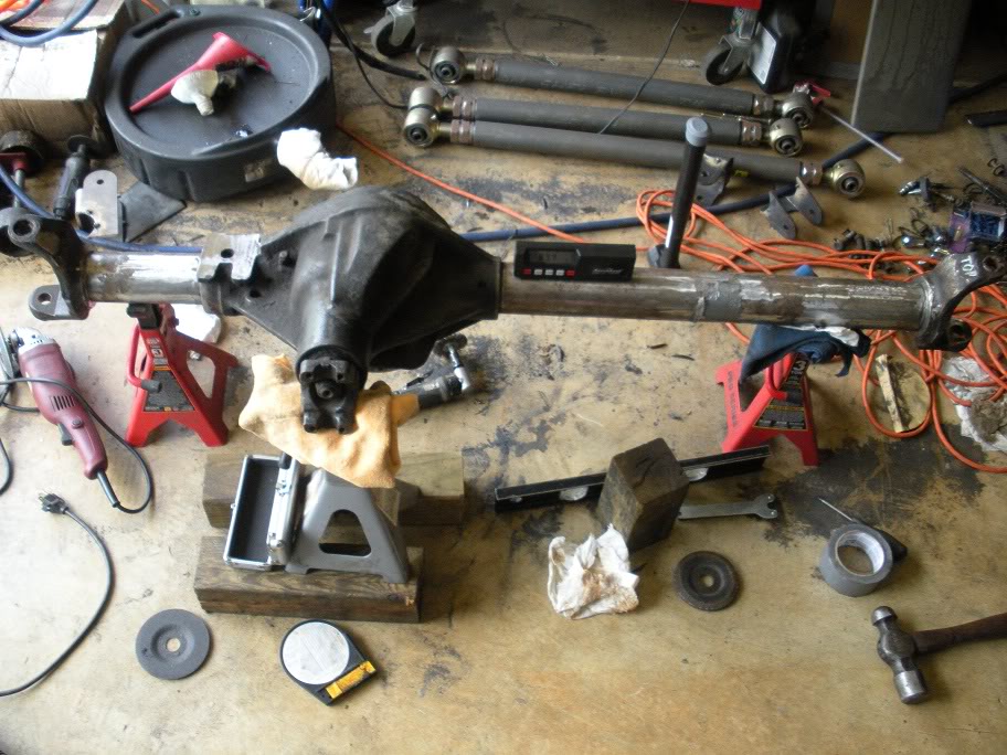
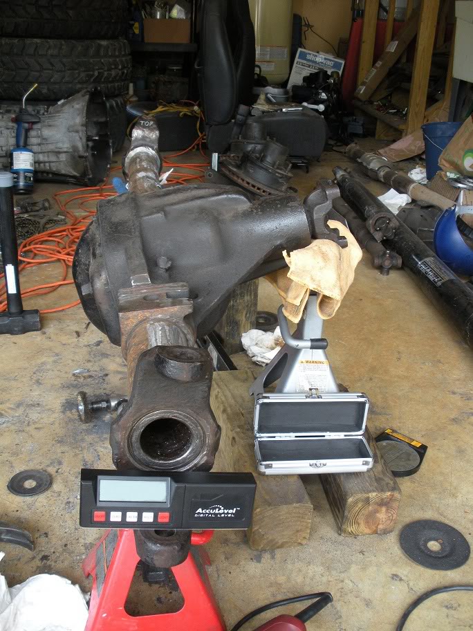
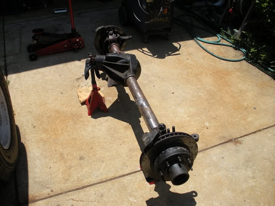
So with the angle known, the axle can come back out from under the truck. I set the axle up in the garage mocking the 14 degree pinion angle...
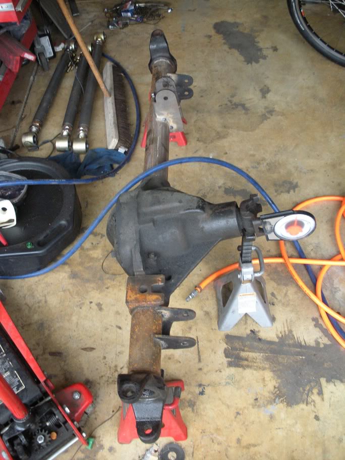
So where I stand now, if I were to set the castor at -6 degrees (middle of the desired range) with the pinion at 14 degrees up, I'd have a plus or minus 1-2 degree tolerance for fine tuning the axle later (once it actually has weight on it) while still keeping acceptable driveline, steering, and coil bucket angles.
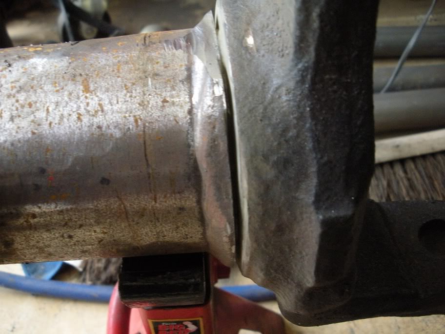
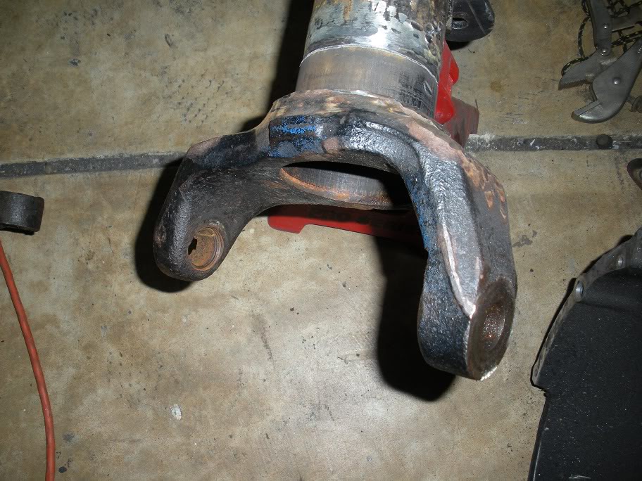
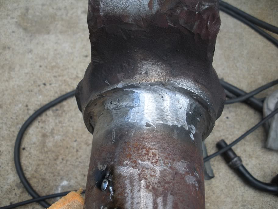
With the axle set up on jackstands and the required angles figured out, the inner knuckle C's need to be removed. Since they are welded on, the welds just need to be ground off and the inner knuckle C's banged off with a BFH.
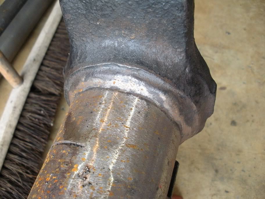
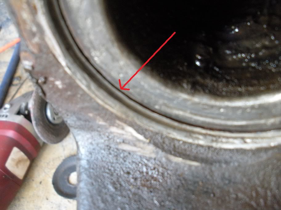
I made the first cut with my angle grinder...
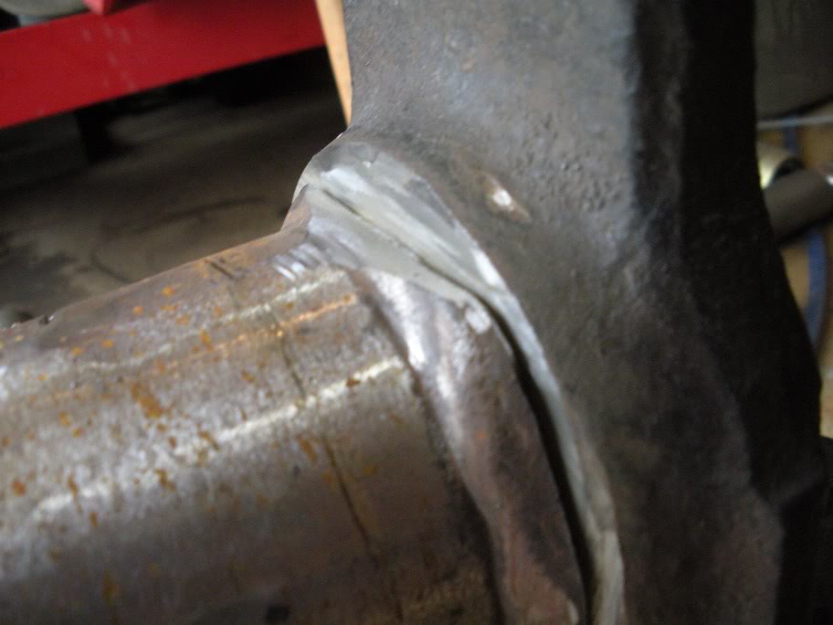
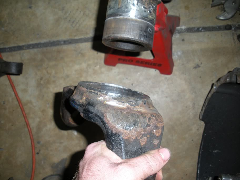
And then I ground down the rest of that weld. Once it was ground down, I started beating on it with a hammer. While beating on it, you need to look for the stress crack to form at the joint, and if it doesn't after a few hard blows, put the hammer down and do some more grinding!! Once the stress crack forms, you'll see this...
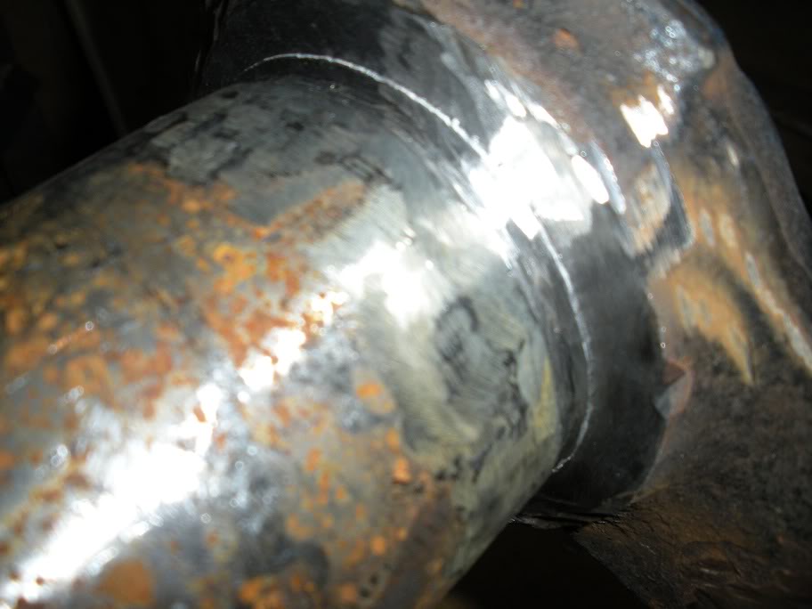
Then just drive it home with the BFH!!!
And then do the other side...
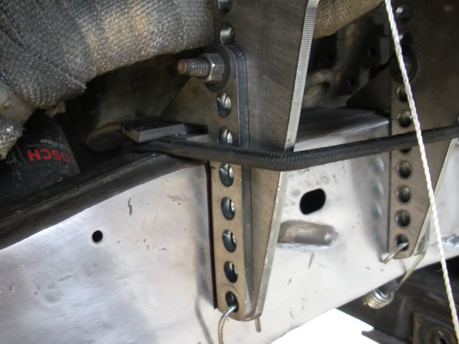
Now I just have to wait for the digital angle finder I ordered to get here. The castor needs to be set very accurately so the two sides aren't different! My angle finder you've seen in these pictures is just a cheap one with too much room for error, so I ordered a digital angle finder thats accurate to 1/10 of a degree. Yes, its an expensive angle finder, but its still cheaper than paying someone else to do it later!!!
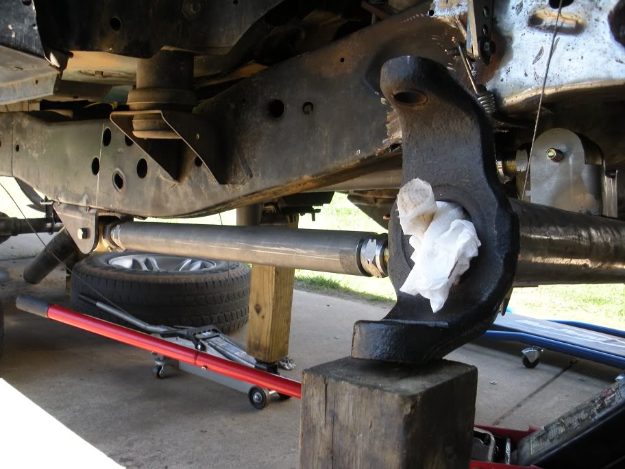
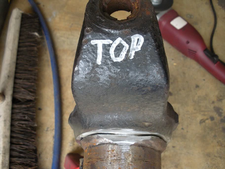
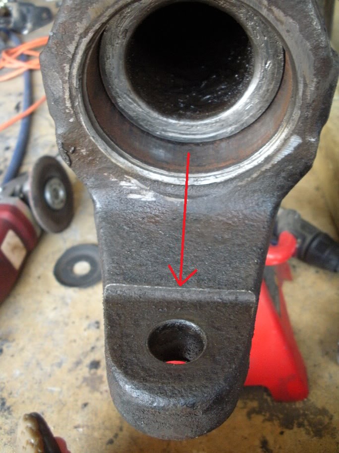
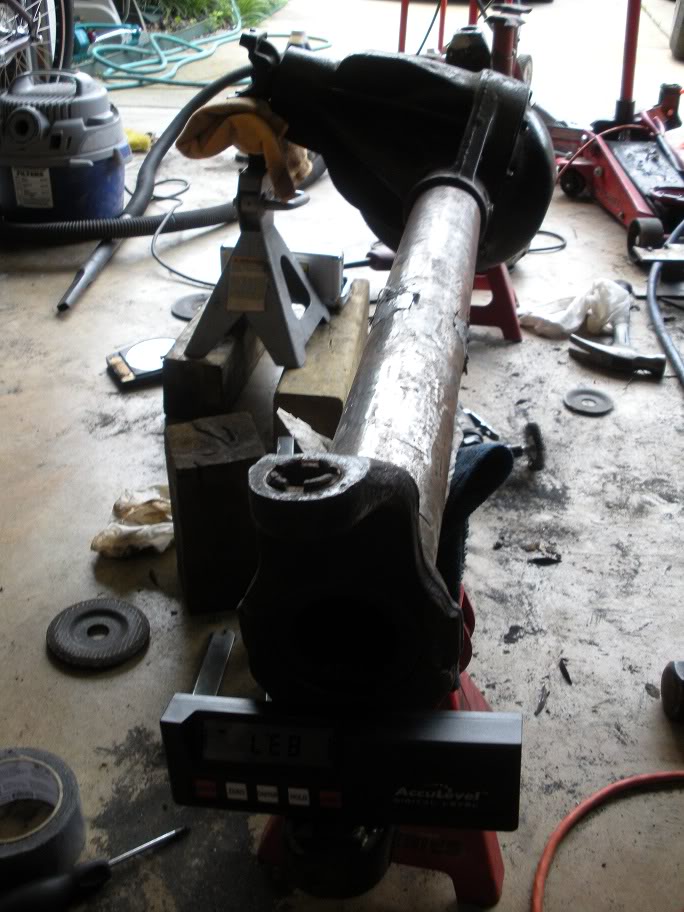
So while I wait, let me point out the upper link bracket on the axle. As you can see its sitting at an odd angle now... this is why it's important to just tack weld the mounts on... because it has to be cut off and turned again!
So where I stand now, if I were to set the castor at -6 degrees (middle of the desired range) with the pinion at 14 degrees up, I'd have a plus or minus 1-2 degree tolerance for fine tuning the axle later (once it actually has weight on it) while still keeping acceptable driveline, steering, and coil bucket angles.
With the axle set up on jackstands and the required angles figured out, the inner knuckle C's need to be removed. Since they are welded on, the welds just need to be ground off and the inner knuckle C's banged off with a BFH.
I made the first cut with my angle grinder...
And then I ground down the rest of that weld. Once it was ground down, I started beating on it with a hammer. While beating on it, you need to look for the stress crack to form at the joint, and if it doesn't after a few hard blows, put the hammer down and do some more grinding!! Once the stress crack forms, you'll see this...
Then just drive it home with the BFH!!!
And then do the other side...
Now I just have to wait for the digital angle finder I ordered to get here. The castor needs to be set very accurately so the two sides aren't different! My angle finder you've seen in these pictures is just a cheap one with too much room for error, so I ordered a digital angle finder thats accurate to 1/10 of a degree. Yes, its an expensive angle finder, but its still cheaper than paying someone else to do it later!!!
So while I wait, let me point out the upper link bracket on the axle. As you can see its sitting at an odd angle now... this is why it's important to just tack weld the mounts on... because it has to be cut off and turned again!
#19
05-28-2011, 01:38 PM
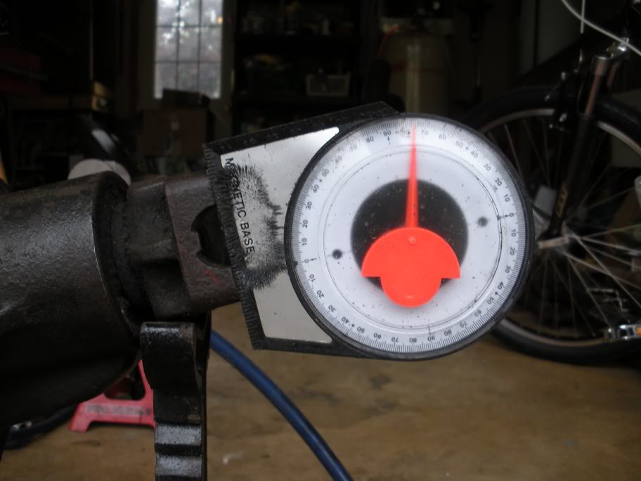
I finally got my angle finder and got the inner knuckle C's put back on.
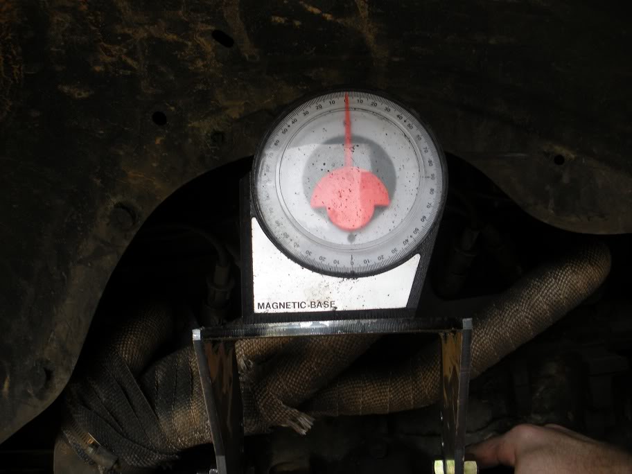
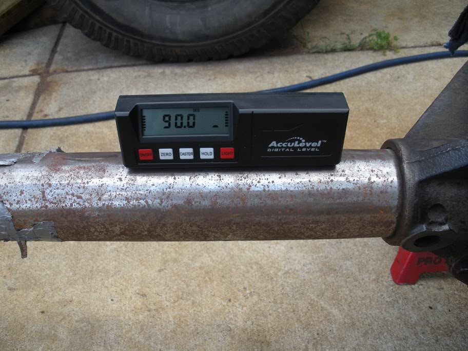
To start, I made sure the axle was level on its jackstands and the pinion 14 degrees up.
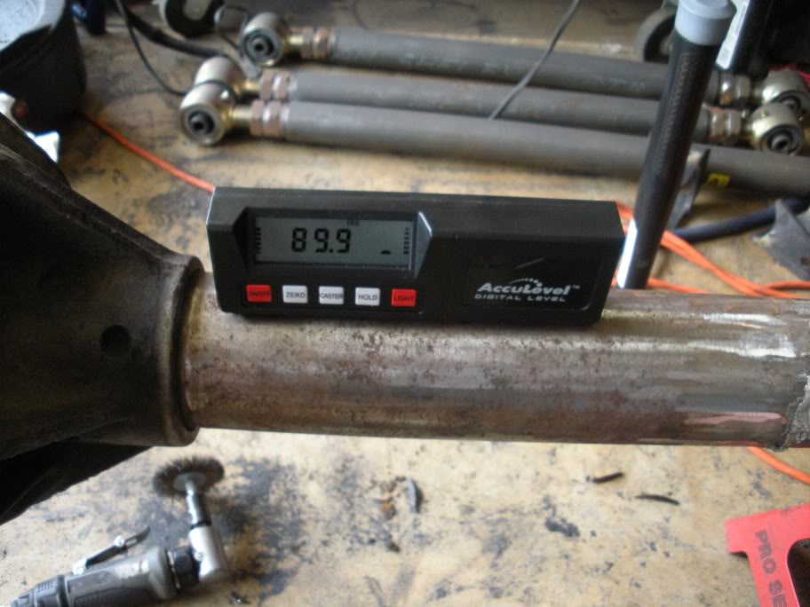
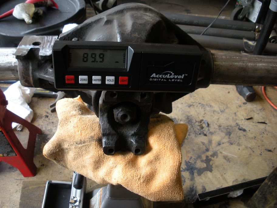
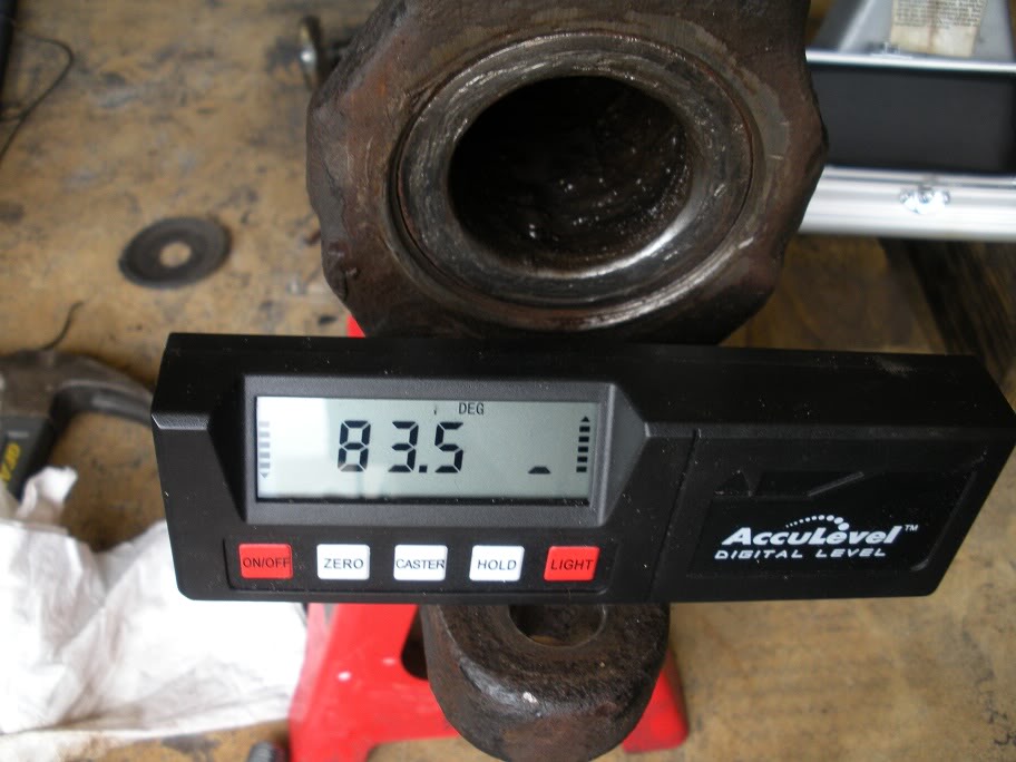
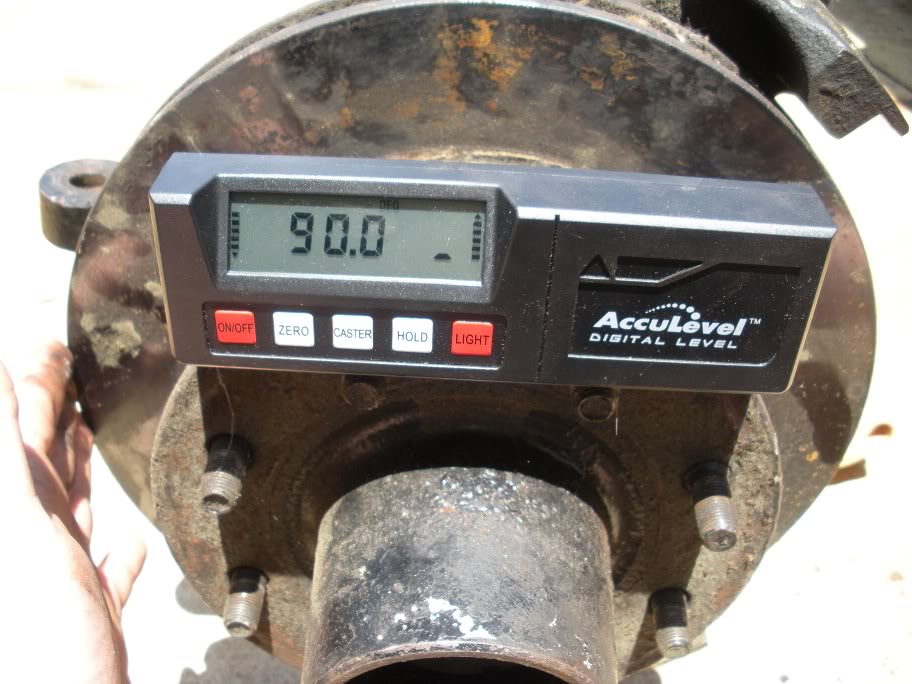
Next, I hammered the inner knucle C's on about an 1/8 of an inch and measured the angle. I used the flat part of the bottom of the C and put the edge of the angle finder against the lip to ensure both sides are measured the same.
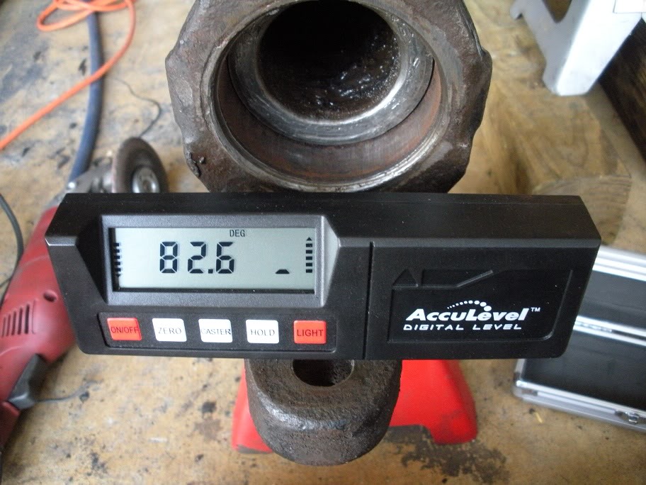
I turned them with a hammer until they were at 6 degrees (84 on the angle finder). Then I ran them home with the hammer. Once they are all the way on, use the lip on the inner knuckle C and the end of the axle tube to make sure they are straight.
Next, I measured remeasured the castor angle to make sure they didn't turn as I was hammering them on.
As you can see, they each turned a little bit. They came out to be around 6.5 degrees and within .1 degrees of each other, which is acceptable enough to not worry about redoing it.
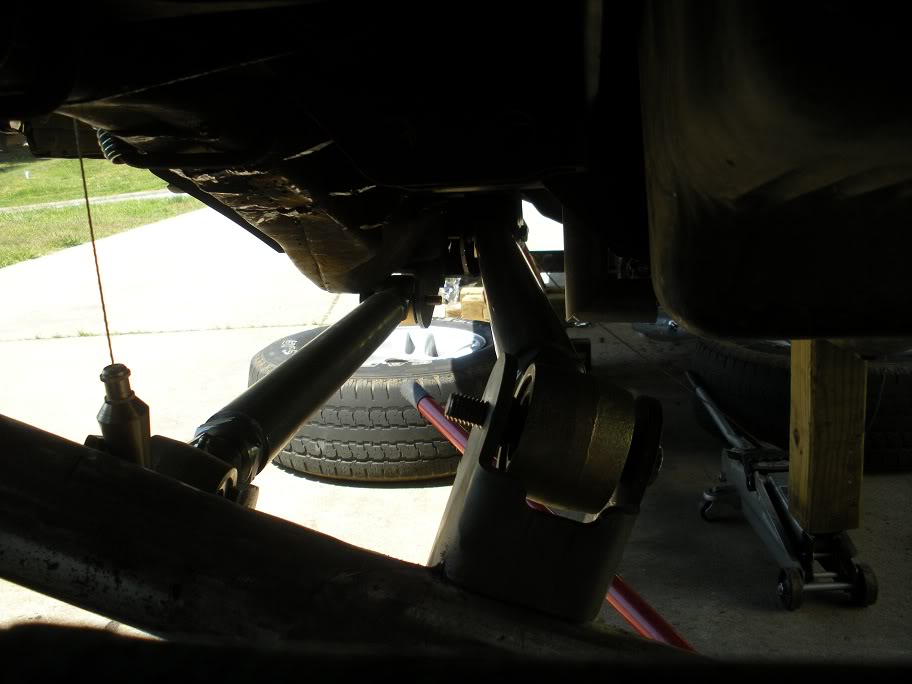
Next, the brackets that were tacked on before need to be turned to the new axle angles.
To start, I made sure the axle was level on its jackstands and the pinion 14 degrees up.
Next, I hammered the inner knucle C's on about an 1/8 of an inch and measured the angle. I used the flat part of the bottom of the C and put the edge of the angle finder against the lip to ensure both sides are measured the same.
I turned them with a hammer until they were at 6 degrees (84 on the angle finder). Then I ran them home with the hammer. Once they are all the way on, use the lip on the inner knuckle C and the end of the axle tube to make sure they are straight.
Next, I measured remeasured the castor angle to make sure they didn't turn as I was hammering them on.
As you can see, they each turned a little bit. They came out to be around 6.5 degrees and within .1 degrees of each other, which is acceptable enough to not worry about redoing it.
Next, the brackets that were tacked on before need to be turned to the new axle angles.
#20
05-28-2011, 01:38 PM
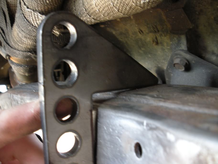
After setting the castor angle on the inner knuckles, the camber needs to be set. Toe is not as important because its adjustable via the tie rods. Now unfortunately, I didn't think about camber before I cut the brackets off, but luckily I bought that '78 F150 and measured the angle on it! But here is my procedure for setting the camber angle...
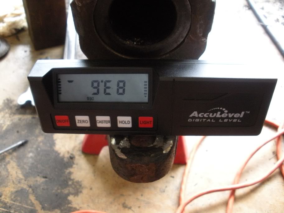
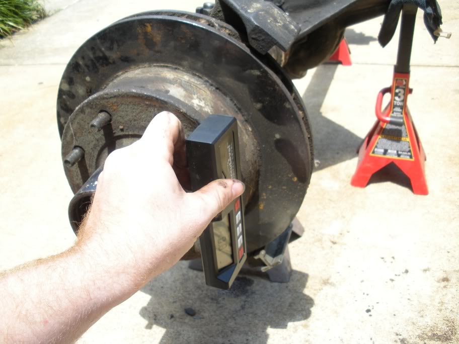
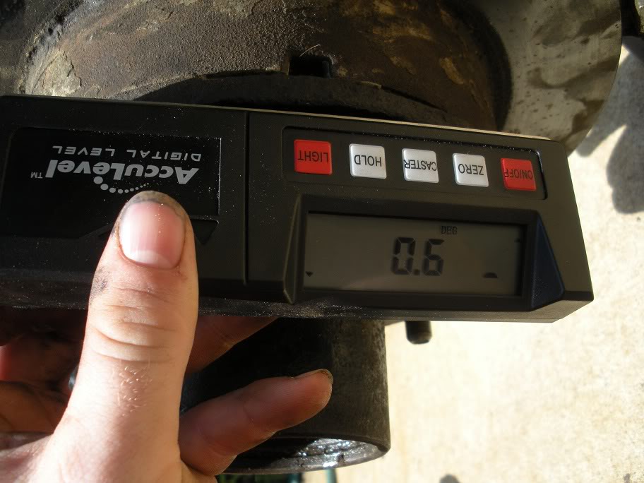
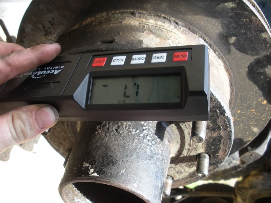
First, I found the desired angle on the F150 by jacking it up, taking off a tire, and making sure the axle was level. Once the axle is level, I aligned 2 consecutive lugs vertically...
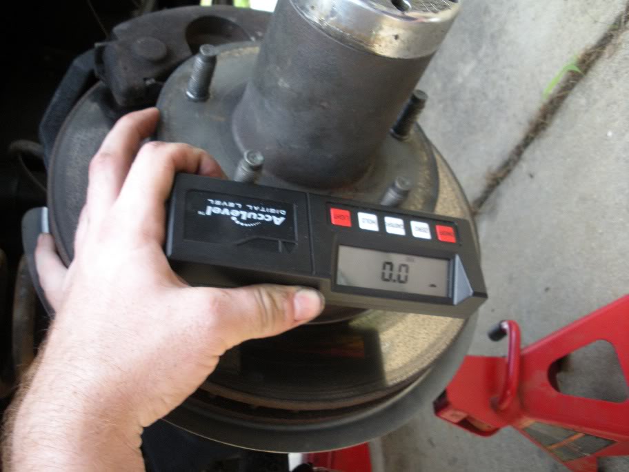
This gave me a vertical backrest for the level. So next, I laid the level against the hub, with the back against those 2 lug nutsl...
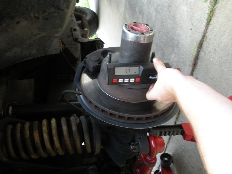
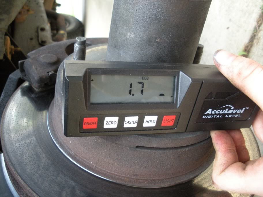
As you can see, the camber is 1.7 degrees top outward. I assume they did this so once weight is on it, it flexes toward 0, but thats just an assumption.
So now that I know the angle I want, I put the outer knuckles on the axle and leveled the axle out (it was moved around since last time I worked on it)...
Then I took initial measurements to see where they sit...
And then did the same on the other side.
As you can see, its nowhere near 1.7. So what I did was tack the c's on at the 3 and 9 oclock positions so the castor wouldn't change while I beat on them. Then I beat on them with the BFH and remeasured and repeated until it was 1.7 degrees...
So repeat that procedure for both sides, and then weld the inner knuckle C's on. I suggest doing this in multiple beads. I layed one down and grinded it smooth...
This is where I stopped to come inside and cool off. I'll continue to weld it later.
By the way, I'm using a 200 amp, 240 volt miller Welder with solid core wire and MIG gas. I borrowed the welder from a buddy who has been helping me the last couple nights to weld the various brackets I had tacked down. The axle should be ready tomorrow to be put in place!! More pictures to come...
First, I found the desired angle on the F150 by jacking it up, taking off a tire, and making sure the axle was level. Once the axle is level, I aligned 2 consecutive lugs vertically...
This gave me a vertical backrest for the level. So next, I laid the level against the hub, with the back against those 2 lug nutsl...
As you can see, the camber is 1.7 degrees top outward. I assume they did this so once weight is on it, it flexes toward 0, but thats just an assumption.
So now that I know the angle I want, I put the outer knuckles on the axle and leveled the axle out (it was moved around since last time I worked on it)...
Then I took initial measurements to see where they sit...
And then did the same on the other side.
As you can see, its nowhere near 1.7. So what I did was tack the c's on at the 3 and 9 oclock positions so the castor wouldn't change while I beat on them. Then I beat on them with the BFH and remeasured and repeated until it was 1.7 degrees...
So repeat that procedure for both sides, and then weld the inner knuckle C's on. I suggest doing this in multiple beads. I layed one down and grinded it smooth...
This is where I stopped to come inside and cool off. I'll continue to weld it later.
By the way, I'm using a 200 amp, 240 volt miller Welder with solid core wire and MIG gas. I borrowed the welder from a buddy who has been helping me the last couple nights to weld the various brackets I had tacked down. The axle should be ready tomorrow to be put in place!! More pictures to come...