

Fuel level sending unit for 87 dakota?

Thread Starter
|
Registered User
Joined: Apr 2013
Posts: 19
Likes: 0
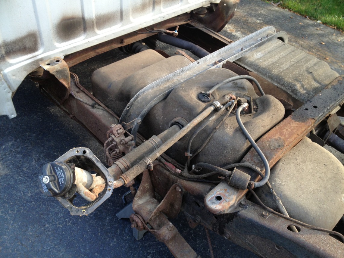
The joy's of having a carb'd dakota. Dealer wants 400 for a new one. Nobody local has one, can't even find one only for under 250. Only thing appears to be universal which isn't tempting at all. Not even 100% positive it is the sending unit but the gauge is always on empty.
I'm hoping the one that's in there now can be fixed but if not, anyone know where to pick one up?
22 gallon tank, 3.9 v6
I'm hoping the one that's in there now can be fixed but if not, anyone know where to pick one up?
The joy's of having a carb'd dakota. Dealer wants 400 for a new one. Nobody local has one, can't even find one only for under 250. Only thing appears to be universal which isn't tempting at all. Not even 100% positive it is the sending unit but the gauge is always on empty.
I'm hoping the one that's in there now can be fixed but if not, anyone know where to pick one up?
22 gallon tank, 3.9 v6
Last edited by Moffman; Jun 25, 2013 at 02:21 AM.

All Star
Joined: Mar 2013
Posts: 783
Likes: 0
From: Eastside Tucson AZ
Have you pulled the sender out of the tank? Sometimes senders get weak because of deposits on the wire that the sender contact rides on. A good cleaning might fix it.
I had a sender go bad, the wire winding broke. While I ended up just buying a new sender, it seemed to me that the winding could have been replaced and that would have fixed it. I think I recall a You Tube video about how to do it--you might try to Google repairing a bad fuel sender and see what you can come up with.
I think you need to have a paradigm shift in your thinking, away from finding a replacement towards finding a way to repair what you have. Think as if you live in the third world someplace. I think you can fix this if you do some studyin' and thinkin'.

Record Breaker
Joined: Nov 2011
Posts: 1,013
Likes: 2
From: Ontario, Canada
Have you tested the voltage to/from the sender unit or to the gauge (use a multi-meter and not just a circuit tester)? Chrysler had a lousy design for the gauge wiring - they used a flexible printed circuit board to hook up all the signal and wiring to the gauges and the printed circuit on these boards had a habit of corroding from any water leak around the window. The gauge will be wired to get a signal from the sender as well as 12 volts. If the 12 volt line (or ground) to the gauge is broken or dead for any reason, the gauge will read zero. If the signal from the sender is non-existant, you should read 12 volts.
The sender/pump is most likely 1 unit like it is on most other vehicles of that time and that's why it costs so much. With the vehicle running, you know that the pump works, so you know that at least 12 volts goes to the pump unit. The sender portion is a variable resister that gives a voltage output that's proportional to the level of the float, so I would test the group of wires that are connected to the pump module - 1 or those wires is ground (or -12 volts), one wire is +12 volts, used to feed the sender and the pump, and the third wire is the resultant signal voltage that comes from the sender showing where the float is. This sender voltage will be less than 12 volts and could be fairly low depending on how much fuel is in the tank - if there's voltage showing between the ground and this wire, your sender is most likely good and the problem would be around the gauge, but if there is no voltage here, then the sender is shot. I think you have a voltage to the gauge problem and not a sender problem.
The sender/pump is most likely 1 unit like it is on most other vehicles of that time and that's why it costs so much. With the vehicle running, you know that the pump works, so you know that at least 12 volts goes to the pump unit. The sender portion is a variable resister that gives a voltage output that's proportional to the level of the float, so I would test the group of wires that are connected to the pump module - 1 or those wires is ground (or -12 volts), one wire is +12 volts, used to feed the sender and the pump, and the third wire is the resultant signal voltage that comes from the sender showing where the float is. This sender voltage will be less than 12 volts and could be fairly low depending on how much fuel is in the tank - if there's voltage showing between the ground and this wire, your sender is most likely good and the problem would be around the gauge, but if there is no voltage here, then the sender is shot. I think you have a voltage to the gauge problem and not a sender problem.
Thread Starter
|
Registered User
Joined: Apr 2013
Posts: 19
Likes: 0
Have you tested the voltage to/from the sender unit or to the gauge (use a multi-meter and not just a circuit tester)? Chrysler had a lousy design for the gauge wiring - they used a flexible printed circuit board to hook up all the signal and wiring to the gauges and the printed circuit on these boards had a habit of corroding from any water leak around the window. The gauge will be wired to get a signal from the sender as well as 12 volts. If the 12 volt line (or ground) to the gauge is broken or dead for any reason, the gauge will read zero. If the signal from the sender is non-existant, you should read 12 volts.
The sender/pump is most likely 1 unit like it is on most other vehicles of that time and that's why it costs so much. With the vehicle running, you know that the pump works, so you know that at least 12 volts goes to the pump unit. The sender portion is a variable resister that gives a voltage output that's proportional to the level of the float, so I would test the group of wires that are connected to the pump module - 1 or those wires is ground (or -12 volts), one wire is +12 volts, used to feed the sender and the pump, and the third wire is the resultant signal voltage that comes from the sender showing where the float is. This sender voltage will be less than 12 volts and could be fairly low depending on how much fuel is in the tank - if there's voltage showing between the ground and this wire, your sender is most likely good and the problem would be around the gauge, but if there is no voltage here, then the sender is shot. I think you have a voltage to the gauge problem and not a sender problem.
The sender/pump is most likely 1 unit like it is on most other vehicles of that time and that's why it costs so much. With the vehicle running, you know that the pump works, so you know that at least 12 volts goes to the pump unit. The sender portion is a variable resister that gives a voltage output that's proportional to the level of the float, so I would test the group of wires that are connected to the pump module - 1 or those wires is ground (or -12 volts), one wire is +12 volts, used to feed the sender and the pump, and the third wire is the resultant signal voltage that comes from the sender showing where the float is. This sender voltage will be less than 12 volts and could be fairly low depending on how much fuel is in the tank - if there's voltage showing between the ground and this wire, your sender is most likely good and the problem would be around the gauge, but if there is no voltage here, then the sender is shot. I think you have a voltage to the gauge problem and not a sender problem.
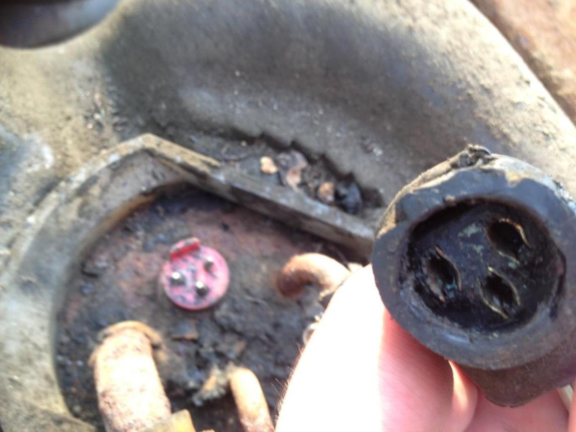
Also need be, how exactly do you remove the sending unit assembly from the tank? I don't see any sort of locking tab around the base of it or anything. It seems like it would just pull right up.

Last edited by Moffman; Jun 25, 2013 at 11:05 PM.
Record Breaker
Joined: Nov 2011
Posts: 1,013
Likes: 2
From: Ontario, Canada
The sender units need 3 wires. The ground is usually fairly easy to spot, look for a black wire, then find the one that has +12 - this one is the input to the sender unit. The third wire will be your sender output signal voltage and this will vary depending on where the float is (how much fuel you have in your tank).
Do not join any of the wires for your tests. First find the +12 volt wire using a multi-meter set to DC voltage. Use a couple of straight pins to stick into the wires - put one into the ground wire and another into one of the other 2. Put the sender connector back on and now you can start the truck. Now, with the multi-meter, put the negative probe onto the ground pin and the positive probe onto the other one & you should read either +12 (or a bit more, this will be the input to the sender), some other voltage less than 12 (this will be the sender voltage signal), or nothing. If you get nothing, stick a pin into the second voltage wire and see what you read. If you get +12, the sender is shot and if you get nothing again, you have an "open" line to the sender. Let us know what you find.
Now, back to the gauge. Again, don't mix or combine the signal and +12 to the gauge, it needs both of these voltages to be able to operate properly.
Trending Topics
Thread Starter
|
Registered User
Joined: Apr 2013
Posts: 19
Likes: 0
Okay I'm a little confused. Let me see if I got this straight. Basically its a 2 way parallel circuit. Let me explain where I am coming from. One wire is 12 volts from the battery that passes through the rheostat and is grounded by another wire which appears to lead to a connector for the rear tail lights or something of that nature. So that's two wires. So third is the 12 volts again wire is the signal output wire for the fuel gauge and the resistance is changed depending on the position of the float? But what I don't understand is why not just run one wire (12 volts) through the rheostat and directly to the gauge. Basically why are there three wires?
Here is a wiring diagram below.
This is how I see it.
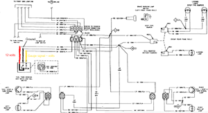
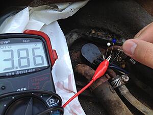
Okay I have 12 volts coming from the blue red wire. The tan is the ground and the blue yellow wire appears to be the signal wire for the gauge. When I measure the voltage between the blue red wire (12 volts) I get a constant 3.86v. However I am measuring no resistance whatsoever which is confusing the heck out of me.
Last edited by Moffman; Jun 27, 2013 at 04:37 PM.
Record Breaker
Joined: Nov 2011
Posts: 1,013
Likes: 2
From: Ontario, Canada
OK, here's a quick explanation for the wires with a rheostat. The main wire winding resistance is connected to the battery, so you have a +12 and ground wire there, and if you set your multimeter to ohms and connect it to these two points, you should read the resistance of the wire wound portion - the whole thing. Now the variable portion of the rheostat, the brush or wiper gives you a selectable output of voltage (this is the "signal") and it's output is the third wire, so connecting your multimeter (ohms setting) to this & the ground will give you the resistance for the piece of the main resistance between the wiper and the ground. The voltage from the "wiper" pin will remain steady unless the float arm in the tank goes up or down. I hope this makes sense, in a circuit when you want a specific voltage, you can use this approach for "voltage splitting" - just remember that your ground (or negative point) is common to the whole circuit.
Thread Starter
|
Registered User
Joined: Apr 2013
Posts: 19
Likes: 0
OK, here's a quick explanation for the wires with a rheostat. The main wire winding resistance is connected to the battery, so you have a +12 and ground wire there, and if you set your multimeter to ohms and connect it to these two points, you should read the resistance of the wire wound portion - the whole thing. Now the variable portion of the rheostat, the brush or wiper gives you a selectable output of voltage (this is the "signal") and it's output is the third wire, so connecting your multimeter (ohms setting) to this & the ground will give you the resistance for the piece of the main resistance between the wiper and the ground. The voltage from the "wiper" pin will remain steady unless the float arm in the tank goes up or down. I hope this makes sense, in a circuit when you want a specific voltage, you can use this approach for "voltage splitting" - just remember that your ground (or negative point) is common to the whole circuit.
Last edited by Moffman; Jun 27, 2013 at 08:17 PM.