Project 51 build thread
#21
Yes, I forgot to mention that that was another reason I switched the rails. I'm not sure what they were thinking but I definitely wasn't about the people who work on them!
#22
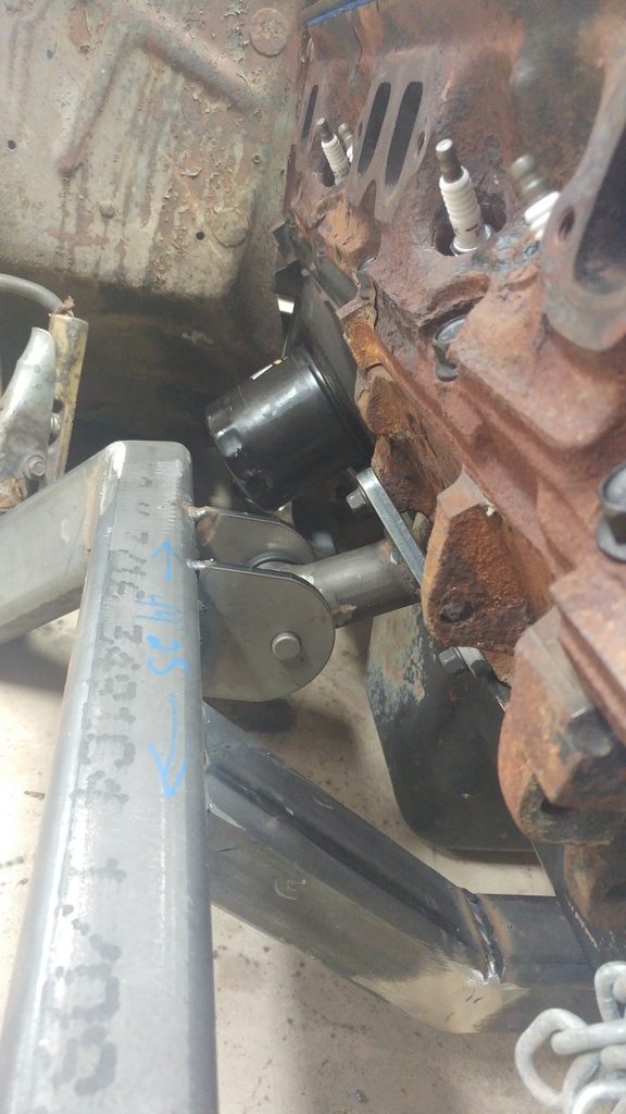
Went out and bought the harbor freight pipe notcher today and the harbor freight bimetallic hole saws. Typically I stay away from harbor freight drill bits and hole saws but they had decent reviews and as long as you use oil and the correct speed they should last. They cut the first few notches without a glitch. Anyways, here's the passenger side mount tacked up.
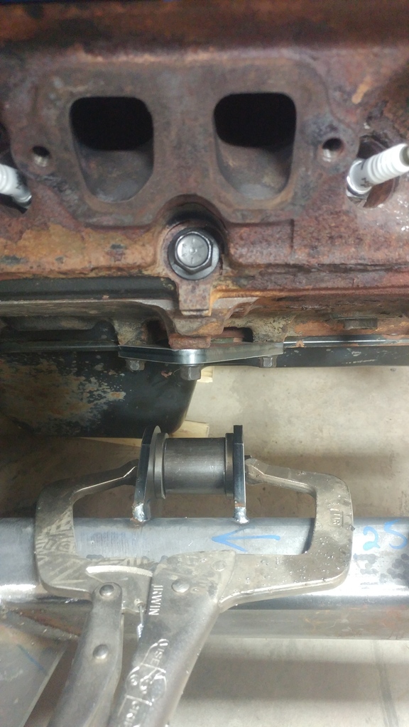
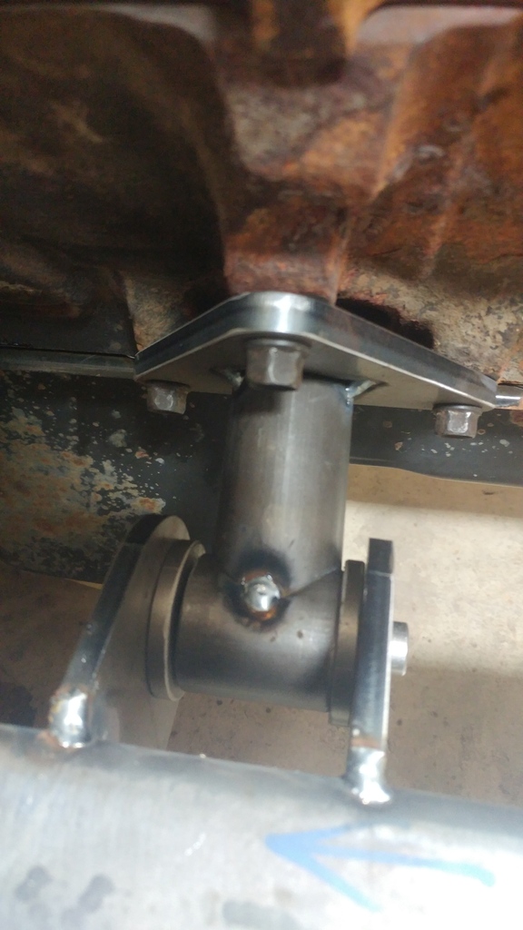
I'll get the driver side tacked up tomorrow then pull both mounts off and weld them up. After that I'll start on the transmission mount.


I'll get the driver side tacked up tomorrow then pull both mounts off and weld them up. After that I'll start on the transmission mount.
#23
I got a decent amount of stuff done the last couple days.
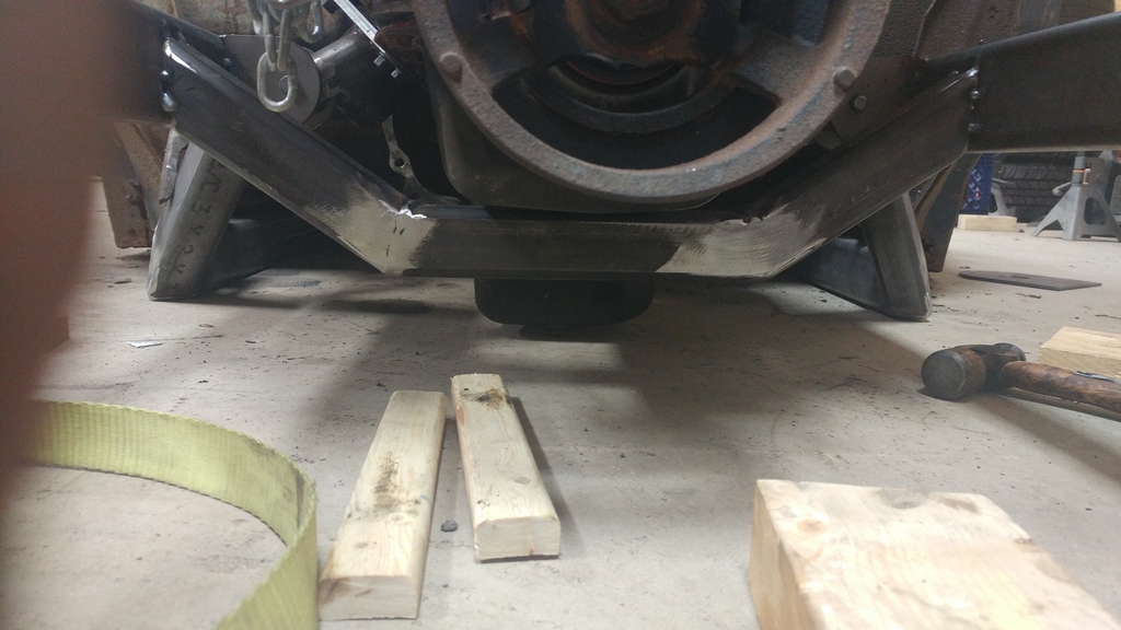
First I got a crossmember welded up and tacked in place under the engine.
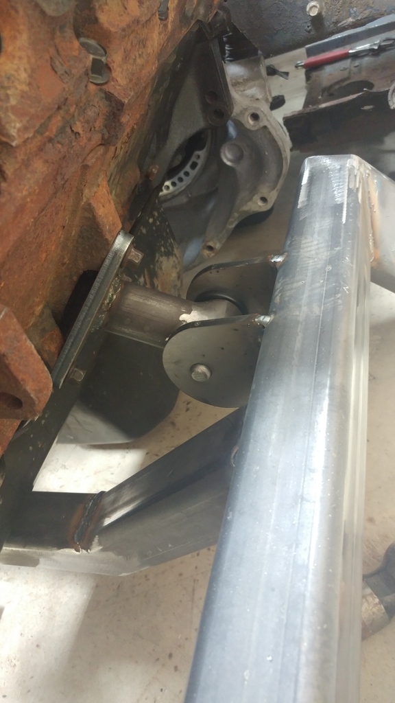
I then pulled the tacked up mounts off and welded them up. Cleaned up the welds and pushed my new prothane bushings in.
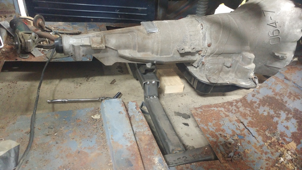
After work today I modified some parts for the trans mount and built a transmission crossmember. For a mount I used the same one that my 67 GTO uses. I had to slot the holes out a little bit but it bolts up perfectly to the 46re. This mount is much smaller than the original truck mount and allows for more room to build s better crossmember. So far I got it all tacked up and tacked into place. I will weld it all up once I pull the frame back out.
First I got a crossmember welded up and tacked in place under the engine.

I then pulled the tacked up mounts off and welded them up. Cleaned up the welds and pushed my new prothane bushings in.


After work today I modified some parts for the trans mount and built a transmission crossmember. For a mount I used the same one that my 67 GTO uses. I had to slot the holes out a little bit but it bolts up perfectly to the 46re. This mount is much smaller than the original truck mount and allows for more room to build s better crossmember. So far I got it all tacked up and tacked into place. I will weld it all up once I pull the frame back out.

#24
It's been a little while since I updated this thread. I haven't had too much time to work on the 51 lately with getting my 67 GTO out of storage and making some changes to that. So anyways:
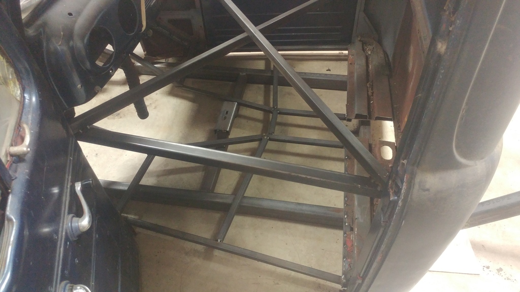
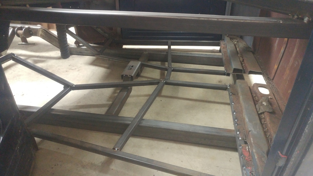
I removed what was left of the floor and built a square tube sub floor out of 1x1 tube.
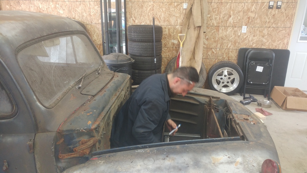
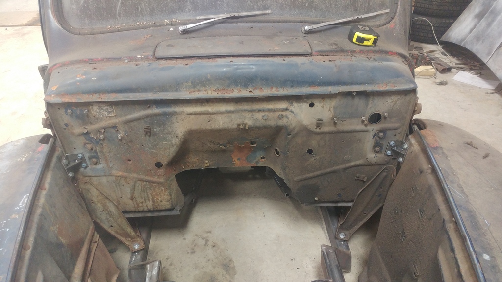
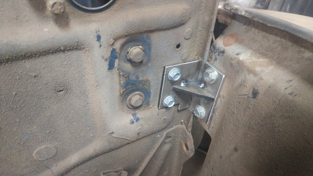
Also we got the frame modified and Z'd back down to mount up the front clip. Ended up cutting 3.5 inches off the backs of the fenders to tilt the front clip back and allow things to line up a little better. We will have to cut 3-3.5 inches off the hood later also to get the hood down to where it needs to be.
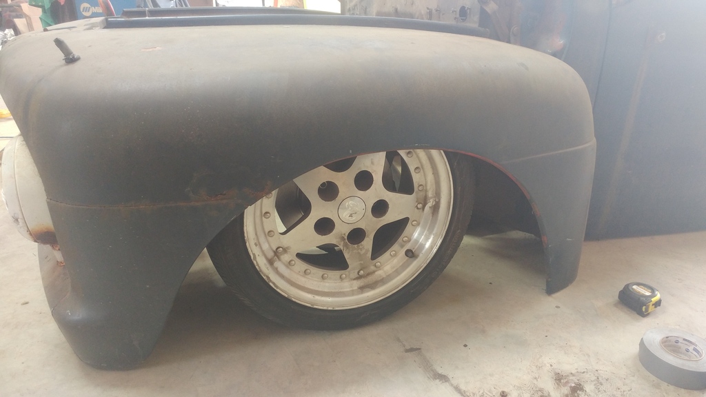
Stuck the front wheel in the fender to see what it'll look like at full drop. Enough tuck?
Im working on getting my car ready and helping my friends get their cars ready for the big car show this coming Sunday so after that I should have a chance to make some more progress. Next I will be building the front and rear suspension.
I removed what was left of the floor and built a square tube sub floor out of 1x1 tube.


Also we got the frame modified and Z'd back down to mount up the front clip. Ended up cutting 3.5 inches off the backs of the fenders to tilt the front clip back and allow things to line up a little better. We will have to cut 3-3.5 inches off the hood later also to get the hood down to where it needs to be.


Stuck the front wheel in the fender to see what it'll look like at full drop. Enough tuck?

Im working on getting my car ready and helping my friends get their cars ready for the big car show this coming Sunday so after that I should have a chance to make some more progress. Next I will be building the front and rear suspension.
#25
Well, itís been quite some time but Iím back at project 51 or as my co-workers like to call it; project death trap lol. I had other projects to take care of the last year and a half so this was put on the back burner. I took it out of storage about a month and a half ago and hereís the progress so far:
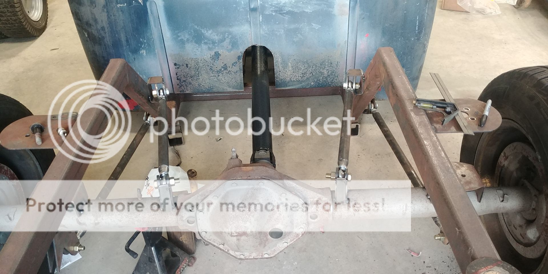
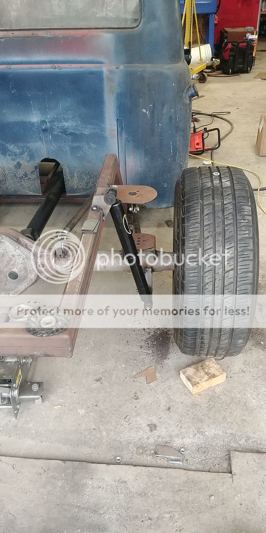
Got the rear 4 link all built and in place
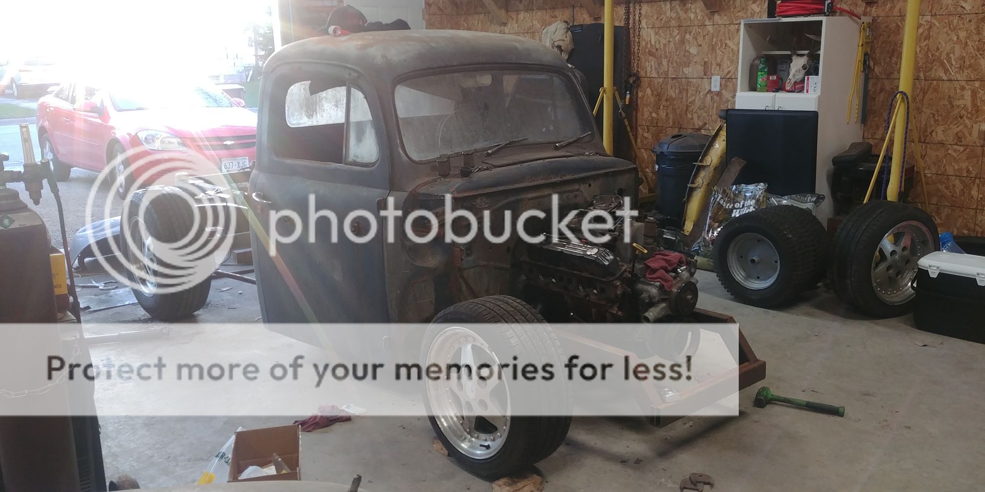
Also took a couple tries but I got the front suspension geometry figured out and working correctly. I used a couple angle gauges to get the steering angles close, but I still built the upper arms adjustable to make sure I can get the angles right later on.
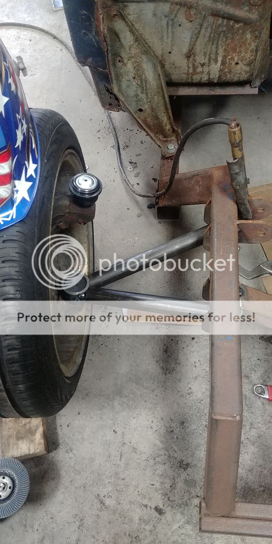
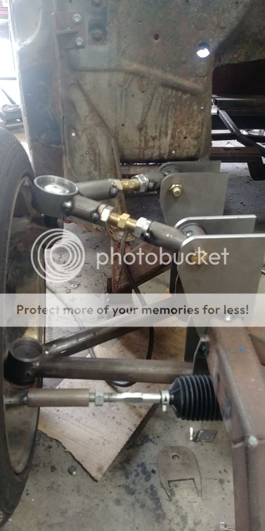
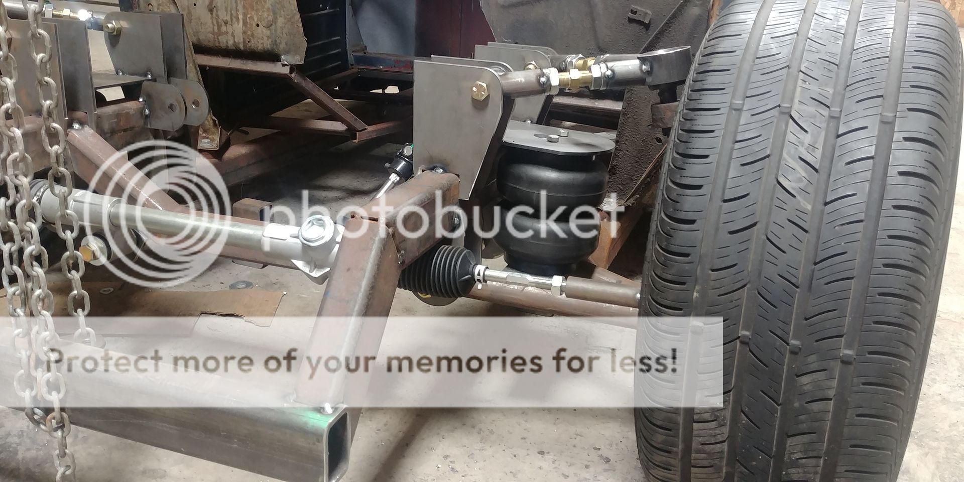
I opted to use a manual Mustang II steering rack due to space limitations and not being able to find a place for a steering gear box. Due to the steering rack being standard thread and the dodge knuckles being a metric taper I had to make my own tie rod ends
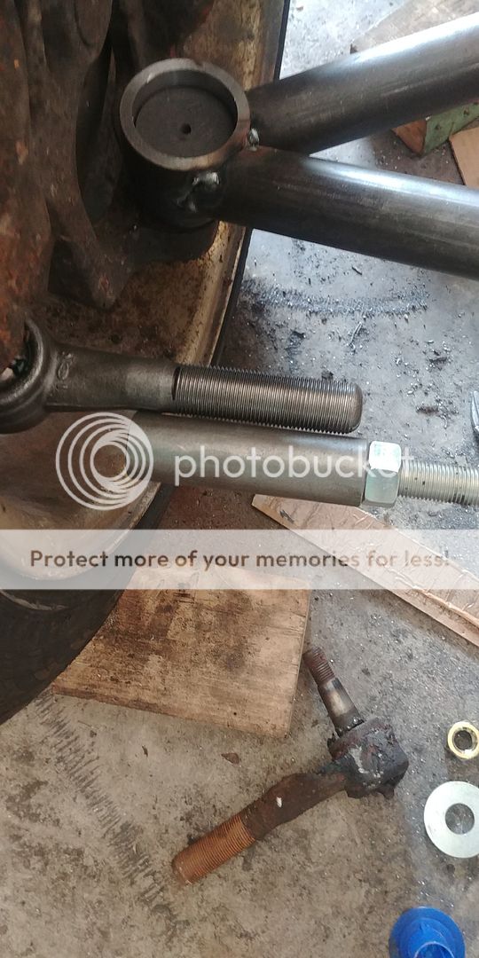
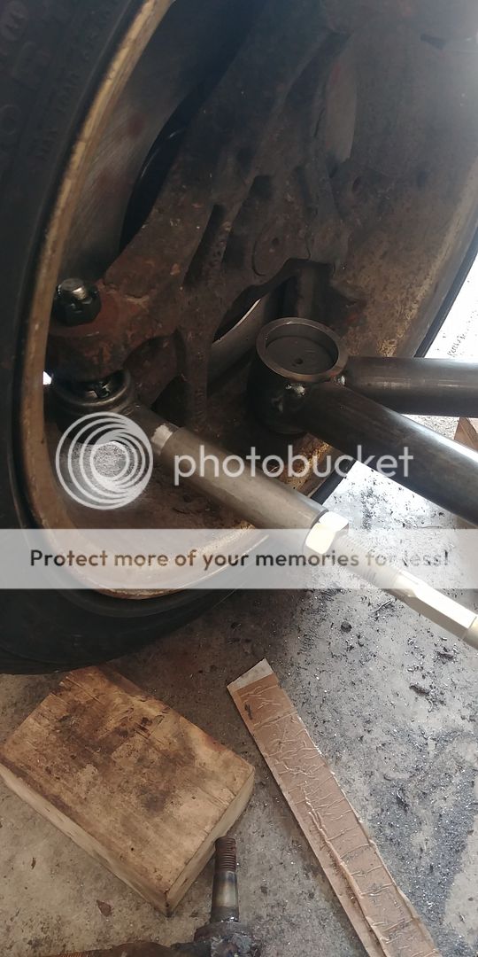
I continually checked everything for clearance at max up, normal ride height, and max down before I welded everything tight
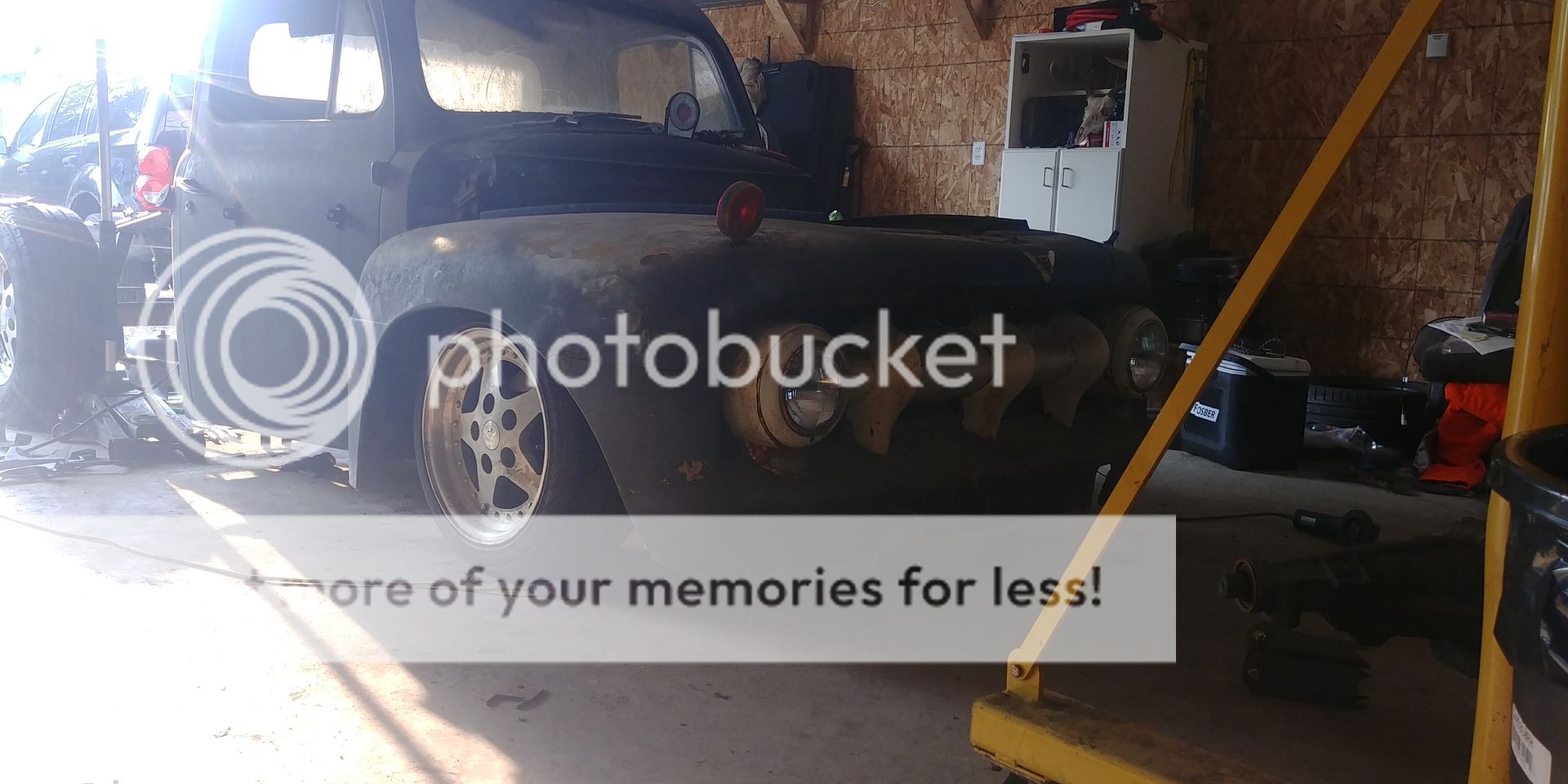
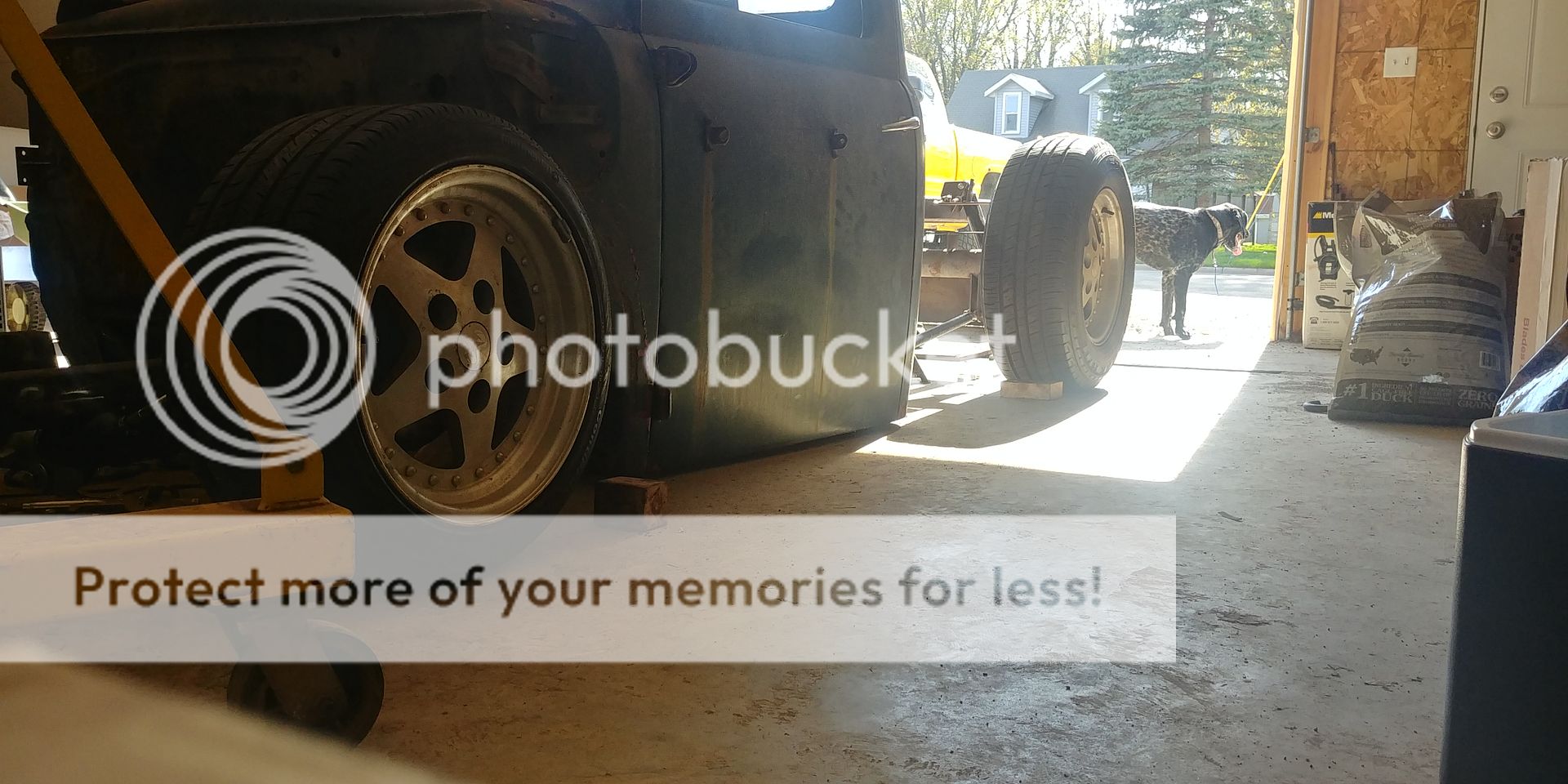
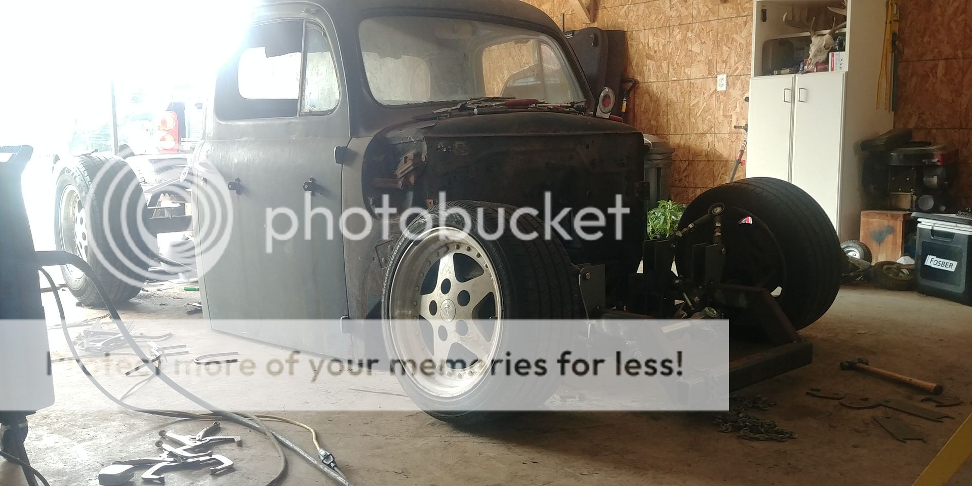
Now that everything moves as it should I removed the body and turned the frame so I could weld every seam.
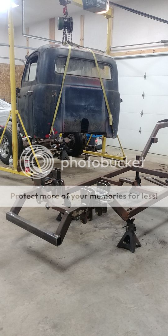
Took me about 5 hours of welding to get everything, then I began reassembly.
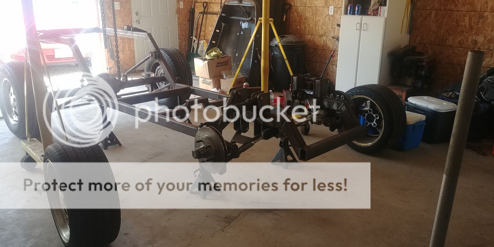
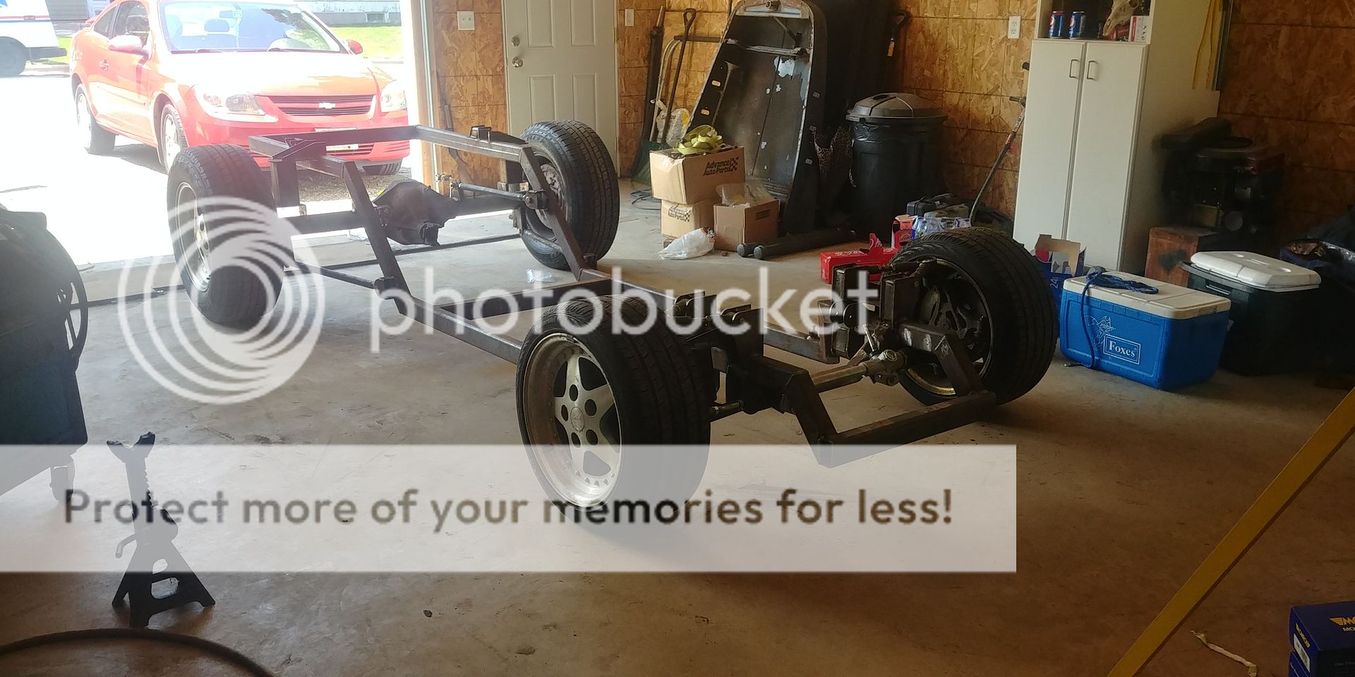
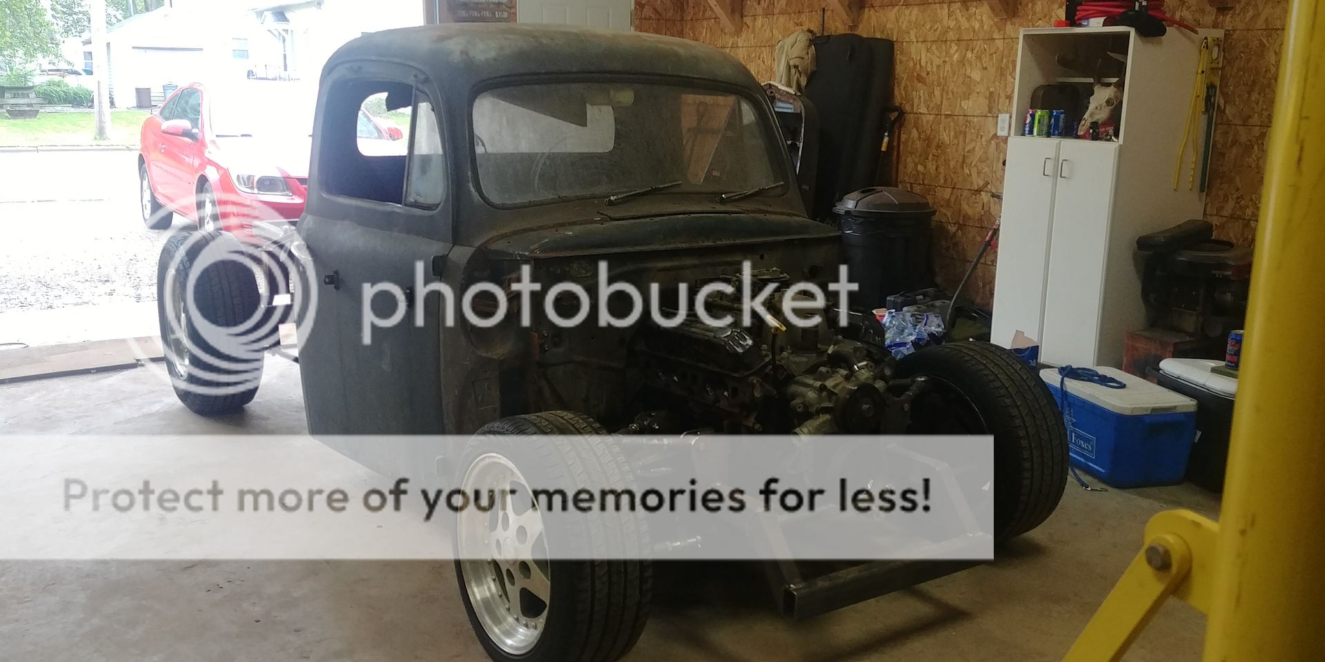
Right now the truck is ready for me to shear up some floor pans and the tunnel and weld them in. Iím hoping to find some time in the next 2 weeks to do that. In the meantime, Iím going to start laying out the wiring harness and removing unnecessary wires. I will be eliminating the factory fuse block and be using an aftermarket 9 circuit block. Realistically the truck will only need 3 circuits not including the necessary ones for the pcm and fuel pump. As of now I can roll the truck in and out with ease. As it sits I would estimate it to weigh around 1200#. All said and done I will be surprised if it weighs 2500#
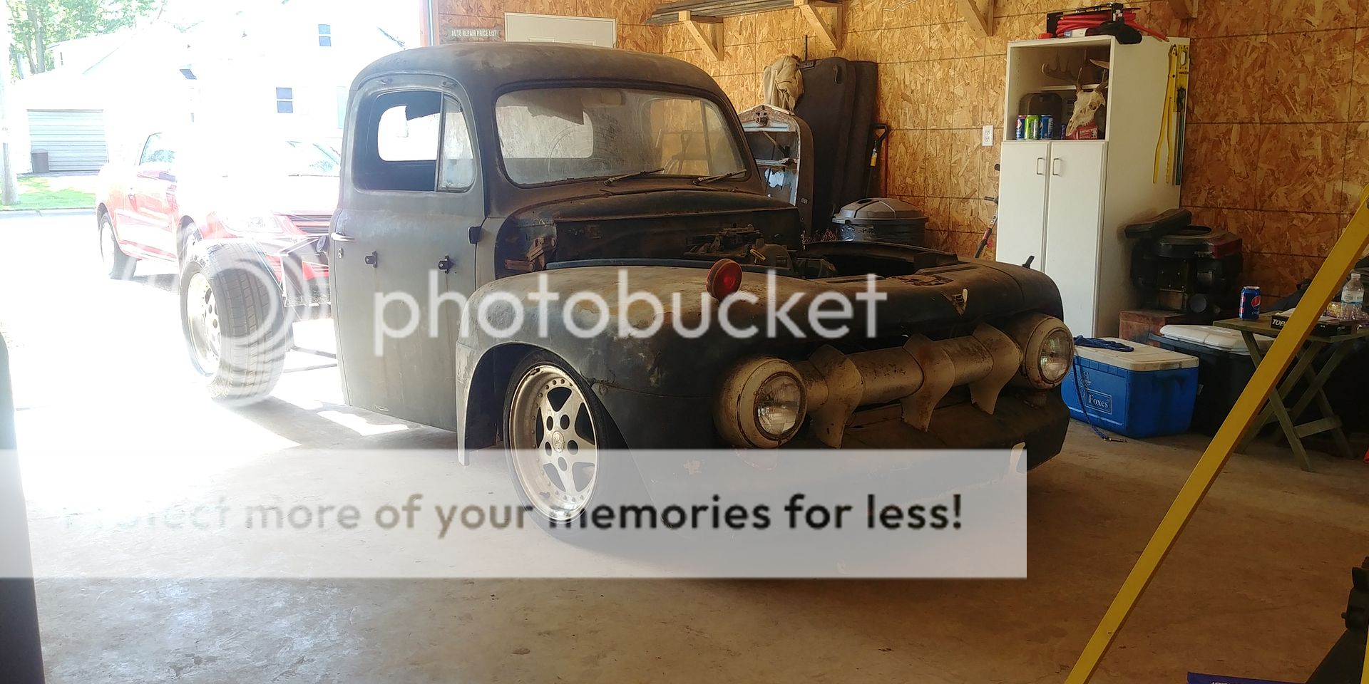
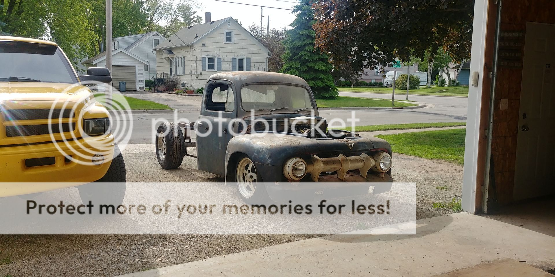
Got the rear 4 link all built and in place


Also took a couple tries but I got the front suspension geometry figured out and working correctly. I used a couple angle gauges to get the steering angles close, but I still built the upper arms adjustable to make sure I can get the angles right later on.


I opted to use a manual Mustang II steering rack due to space limitations and not being able to find a place for a steering gear box. Due to the steering rack being standard thread and the dodge knuckles being a metric taper I had to make my own tie rod ends


I continually checked everything for clearance at max up, normal ride height, and max down before I welded everything tight


Now that everything moves as it should I removed the body and turned the frame so I could weld every seam.

Took me about 5 hours of welding to get everything, then I began reassembly.


Right now the truck is ready for me to shear up some floor pans and the tunnel and weld them in. Iím hoping to find some time in the next 2 weeks to do that. In the meantime, Iím going to start laying out the wiring harness and removing unnecessary wires. I will be eliminating the factory fuse block and be using an aftermarket 9 circuit block. Realistically the truck will only need 3 circuits not including the necessary ones for the pcm and fuel pump. As of now I can roll the truck in and out with ease. As it sits I would estimate it to weigh around 1200#. All said and done I will be surprised if it weighs 2500#


Last edited by 97ramrod1500; 06-26-2019 at 09:38 PM.
The following 2 users liked this post by 97ramrod1500:
2bit (08-03-2019),
frankie_b_jr (06-27-2019)
#27
Since i deleted the power power steering pump and a/c compressor I needed to re-route my serpentine belt. I replaced the smooth idler pulley with a grooved one and got a new belt at the proper length
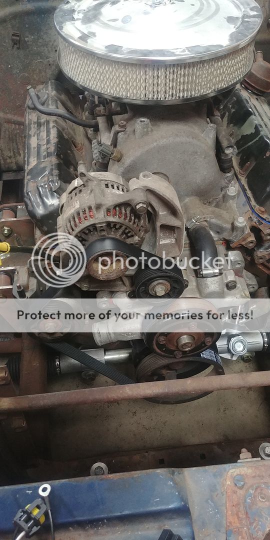
while waiting to get a chance to bring my truck into the metslshop to begin the floors and tunnel, I decided to start the wiring. I pulled apart the engine harness and removed the wires No longer necessary. I began routing the harness and will get the mounts made up to mount the pcm, fuse block, relays, etc under the dash so itís hidden. I have been spending a ton of time going through wiring diagrams and will wire everything up before I mount it under the dash. Using the factory fuse blocks would probably be Ďeasierí, but would take up a lot of unnecessary space.
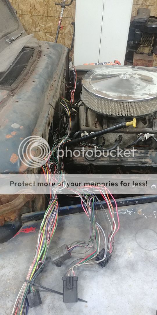
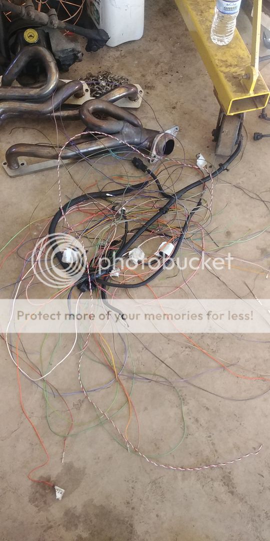
my fuel tank got lasered and bent up this week so I will find some time next week to tig it up and get the fuel pump fit into it. Iím really waiting to get the floors in, cause once thatís done the truck will come together pretty quick. Hopefully I get this rats nest of wiring figured out and everything working.

while waiting to get a chance to bring my truck into the metslshop to begin the floors and tunnel, I decided to start the wiring. I pulled apart the engine harness and removed the wires No longer necessary. I began routing the harness and will get the mounts made up to mount the pcm, fuse block, relays, etc under the dash so itís hidden. I have been spending a ton of time going through wiring diagrams and will wire everything up before I mount it under the dash. Using the factory fuse blocks would probably be Ďeasierí, but would take up a lot of unnecessary space.


my fuel tank got lasered and bent up this week so I will find some time next week to tig it up and get the fuel pump fit into it. Iím really waiting to get the floors in, cause once thatís done the truck will come together pretty quick. Hopefully I get this rats nest of wiring figured out and everything working.
#28
Between the holiday and vacation I havenít had a ton of time to spend on the Death Trap the past few weeks. Nonetheless, the wiring is coming along nicely. I made a bracket to hold the pcm, new fuse block all the relays and the signal converter for the vehicle speed sensor. I actually took all of yesterday afternoon drawing wiring diagrams for the main circuits with the new fuse block to make it easier on myself.
This will mount to the new glovebox and keep everything hidden behind the dash
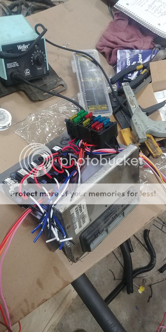
Right now Iím still waiting on the glovebox as well as trying to find time yet to get the truck to the shop to make floor pans. Iíll keep plugging away at the wiring so the engine will hopefully be ready to crank over in the coming weeks. Iíve spent countless hours going through wiring diagrams so hopefully Iíve got everything I need covered.
This will mount to the new glovebox and keep everything hidden behind the dash

Right now Iím still waiting on the glovebox as well as trying to find time yet to get the truck to the shop to make floor pans. Iíll keep plugging away at the wiring so the engine will hopefully be ready to crank over in the coming weeks. Iíve spent countless hours going through wiring diagrams so hopefully Iíve got everything I need covered.
#29
Between the holiday and vacation I havenít had a ton of time to spend on the Death Trap the past few weeks. Nonetheless, the wiring is coming along nicely. I made a bracket to hold the pcm, new fuse block all the relays and the signal converter for the vehicle speed sensor. I actually took all of yesterday afternoon drawing wiring diagrams for the main circuits with the new fuse block to make it easier on myself.
This will mount to the new glovebox and keep everything hidden behind the dash

Right now Iím still waiting on the glovebox as well as trying to find time yet to get the truck to the shop to make floor pans. Iíll keep plugging away at the wiring so the engine will hopefully be ready to crank over in the coming weeks. Iíve spent countless hours going through wiring diagrams so hopefully Iíve got everything I need covered.
This will mount to the new glovebox and keep everything hidden behind the dash

Right now Iím still waiting on the glovebox as well as trying to find time yet to get the truck to the shop to make floor pans. Iíll keep plugging away at the wiring so the engine will hopefully be ready to crank over in the coming weeks. Iíve spent countless hours going through wiring diagrams so hopefully Iíve got everything I need covered.
#30
My diagrams use the wire colors for the aftermarket fuse block I'm using, really a one-time use I would think. I can send them to you but they won't really apply to your vehicle. If you want them, send me a pm.


