When you click on links to various merchants on this site and make a purchase, this can result in this site earning a commission. Affiliate programs and affiliations include, but are not limited to, the eBay Partner Network.
2nd Gen Ram Tech1994-2001 Rams: This section is for TECHNICAL discussions only, that involve the 1994 through 2001 Rams. For any non-tech discussions, please direct your attention to the "General discussion/NON-tech" sub sections.
I had the same problem on my 2001 ram with the 5.9. I tried a few different things, but my problem ended up being the computer mounted to the firewall on the passenger side. It cost me 250 bucks to replace, but when I put the new one in, it fired right up and I haven't had any problems since. You can go online and search for a new replacement computer they will program the new computer to your vin. I hope this helps.
It doesn't make sense, then of course most electronic failures don't.
The data needed for almost all of the cluster functions come from that buss, tach, speedo, gauges, warning lights...
Can you pull it out far enough to wiggle the connectors on the back while it's on?
This is from the '01 manual:
BUS FAILURE VISUAL SYMPTOM DIAGNOSIS The following visible symptoms or customer complaints, alone or in combination, may indicate a CCD data bus failure:
Airbag Indicator Lamp and Malfuntion Indicator Lamp (MIL) Illuminated Instrument Cluster Gauges (All) Inoperative No Compass Mini-Trip Computer (CMTC) Operation
Last edited by Friar Tuck; Jun 29, 2016 at 10:05 AM.
Joint Connector 7 is a 22-pin connector where all the twisted pair wires for the CCD BUSS terminate.
If you don't mind, I would ask you to reseat it.
It is on the wire harness on the left side of the steering column under the dash per figure 24 in section 8-90 of the manual.
This is the main harness that goes to the large connector on the firewall.
There are two 22-pin connectors there, one above the other.
The lower one is Joint Connector 6, and Joint connector 7 is the upper one. I'm hoping this will fix the NO BUSS problem.
Just disconnect the battery first, don't like to reseat any connector hot.
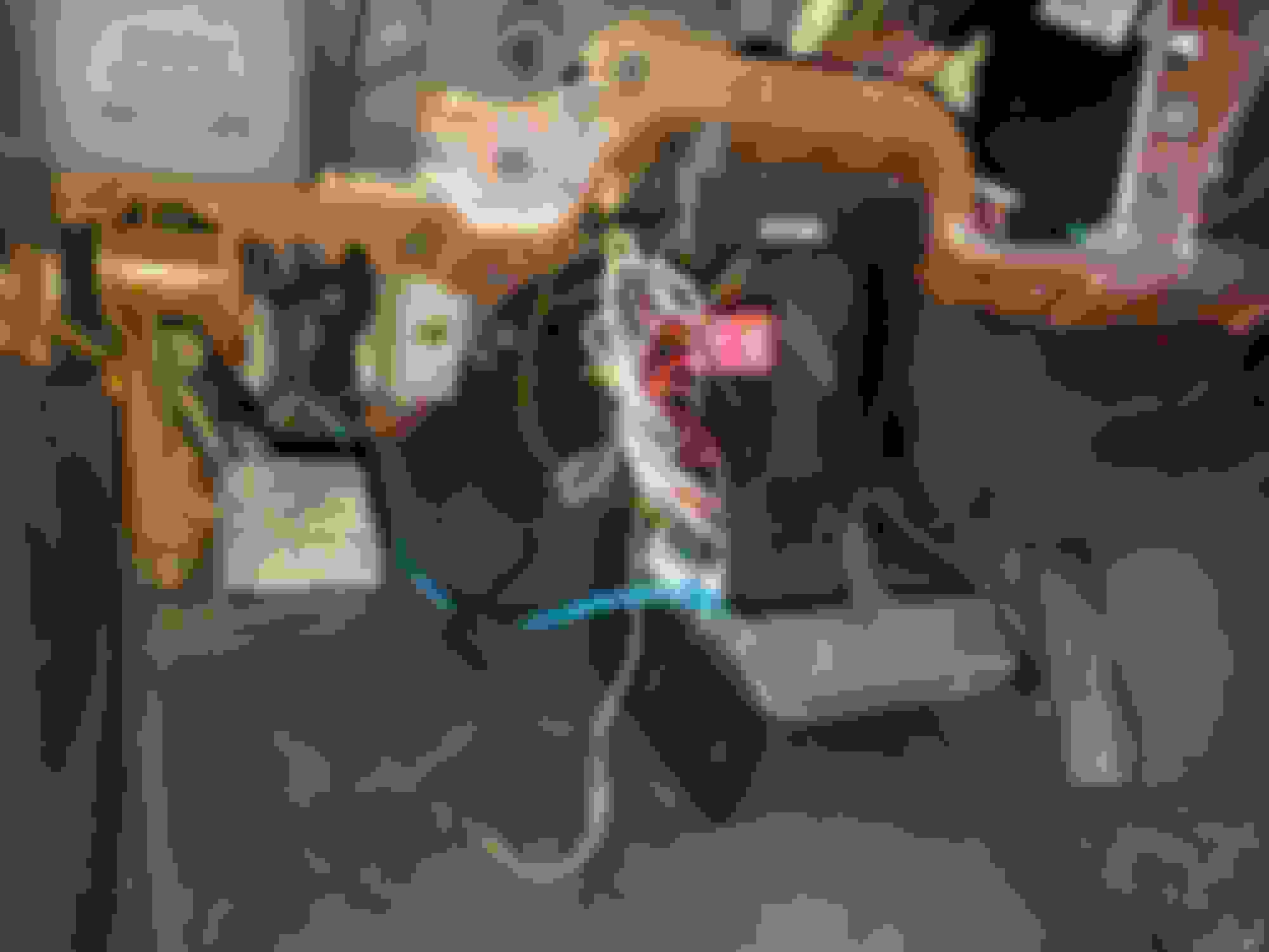
I'm having a little trouble locating Joint Connector 7. Here is my current situation. I'm assuming that I have to take off the rest of the dash to get to it? But before I do as you can see I have a bunch of remote starter crap in my way. Would the joint connectors be something that got removed or wired in to the remote starter?
It should still be there, and in the same place as advertised. Not exactly something you can remove, with some dire consequences. (things stop working.....)
To further help identify these 22 pin connectors, JOINT CONNECTOR 6 has no wire in positions 4, 5, 11, 12, or 13.
JOINT CONNECTOR 7 has no wire in positions 18, 19, 21, and 22.
All of the wires on JOINT CONNECTOR 7 are either VIOLET/BROWN or WHITE/BLACK.
That big white connector with the bolt in the middle is C134. These Joint Connectors should be directly above it.
Last edited by Friar Tuck; Jul 3, 2016 at 01:21 AM.
Finally had time to look back in to this. Found joint connector 6 and 7 (thanks for the help). The violet/brown and white/black one was on the bottom but I disconnected both for good measure. Hooked the battery back up, turned the key, crossed my fingers, and........no bus
After I put you thru all that, I am really surprised. That is the place where all of the CCD Buss wires from all the modules come together to form the buss.
Gonna have to regroup.






 Replace Computer


 CCD BUSS Joint Connector 7
 Joint Connector 7 is a 22-pin connector where all the twisted pair wires for the CCD BUSS terminate.