


How To: Swap Door Switch LEDs [Photo Warning]

WARNING:
YOU ATTEMPT THIS MOD AT YOUR OWN RISK. IF YOU DO NOT KNOW HOW TO SOLDER, ARE NOT COMFORTABLE WITH IT OR DON'T HAVE THE PROPER TOOLS THEN DO NOT ATTEMPT THIS MOD. A SINGLE MISTAKE WILL CAUSE FUSES TO BLOW, WINDOW FAILURE, LOST MONEY, INJURY AND DEATH TO OCCUR (ok, maybe not death)
I CAN NOT AND WILL NOT BE HELD RESPONSIBLE FOR ANY PROBLEMS ARISING FROM THIS MOD. I'M MERELY PROVIDING THE INFORMATION.
__________________________________________________ __________________________________________________ __________________________________________________ ________________
Tools Needed:
A Cat

Soldering Supplies
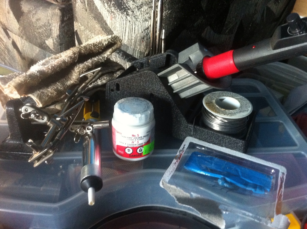
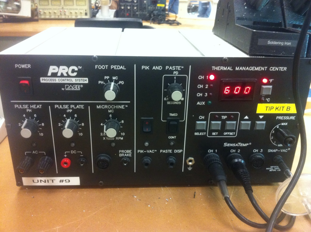
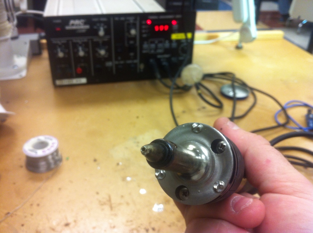
Preferably a very expensive re-work station if you happen to have access to one. This lets you heat and remove the solder in one step. Press a button and it sucks the solder off the board through the nozzle.
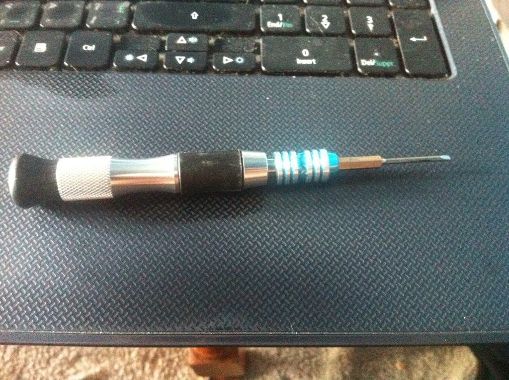
Small Screwdriver (Flat)
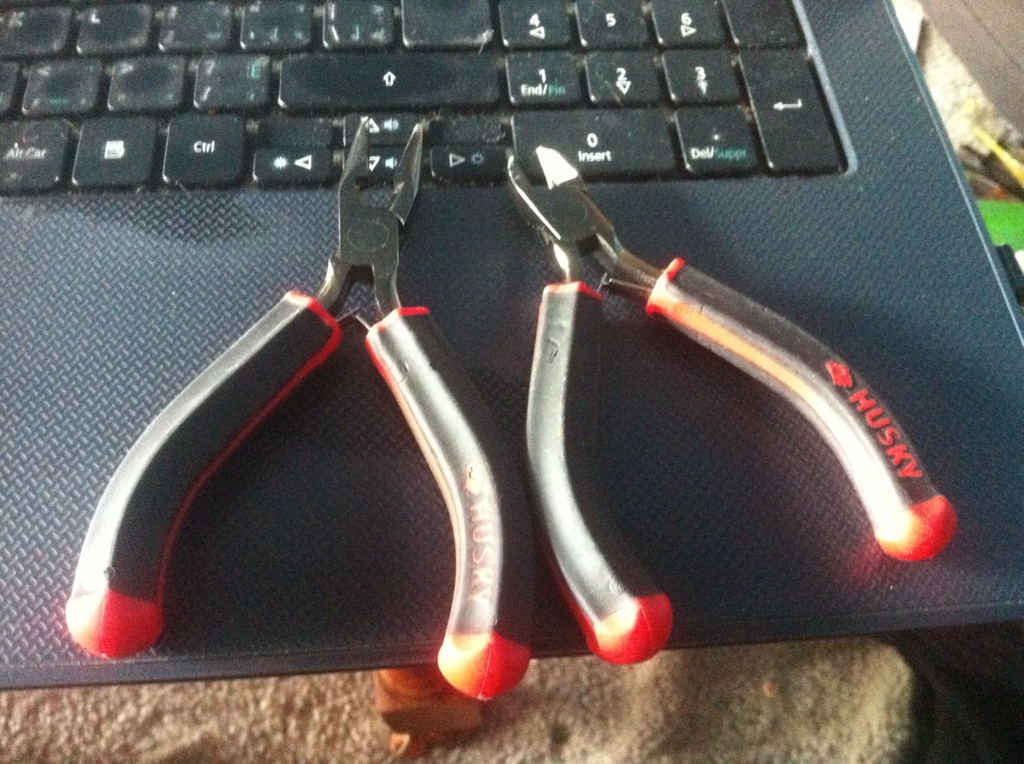
Pliers and Wire Cutters
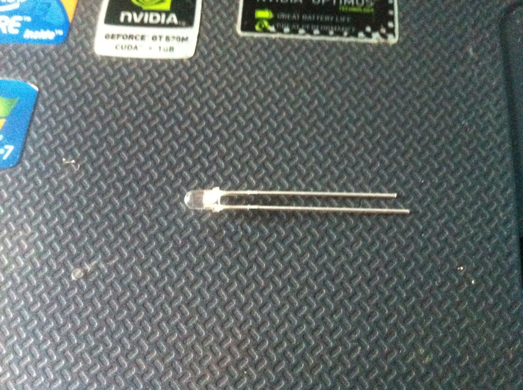
3mm LEDs
Process:
I won't be covering certain steps such as disassembly, because quite frankly if you are unable to figure out how to take something apart you should not be attempting this mod.
Step 1:
Remove the door switch panel according to the service manuals outlined procedure. This is about the only time you will need the manual because removing the switch panel is all Dodge thinks you need to do.
After it's out and has the bezel removed you will need to pull off the switch covers. This can be tricky as they are secured very well to the switches, but you can pry them off in whatever fashion you decide.
Once all of the covers are removed you can open the housing to gain access to the circuit board.
Step 2:
Dodge was crafty here, and made this job as hard as possible to prevent people from messing with things.
There are 14 pins that need to be de-soldered before the circuit board can be removed, and it's impossible to reach the switch pins without removing the board, unless you cut a square out of the housing, but you're still going to have to solder so there is no point in destroying the housing.
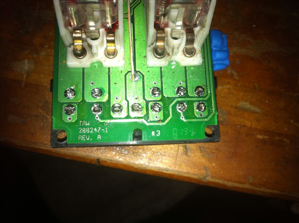
Make sure you have some way to hold the switch assembly secure while you de-solder. I use the blue sticky tack which works fairly well to hold stuff in place.
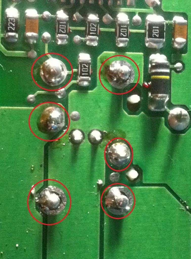
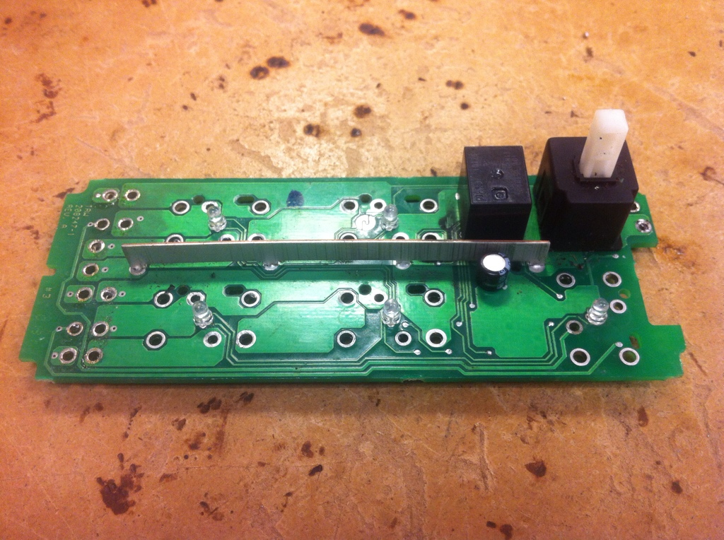
12 pins located here
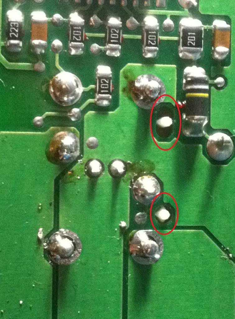
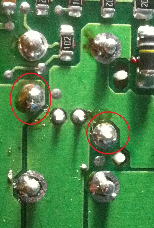
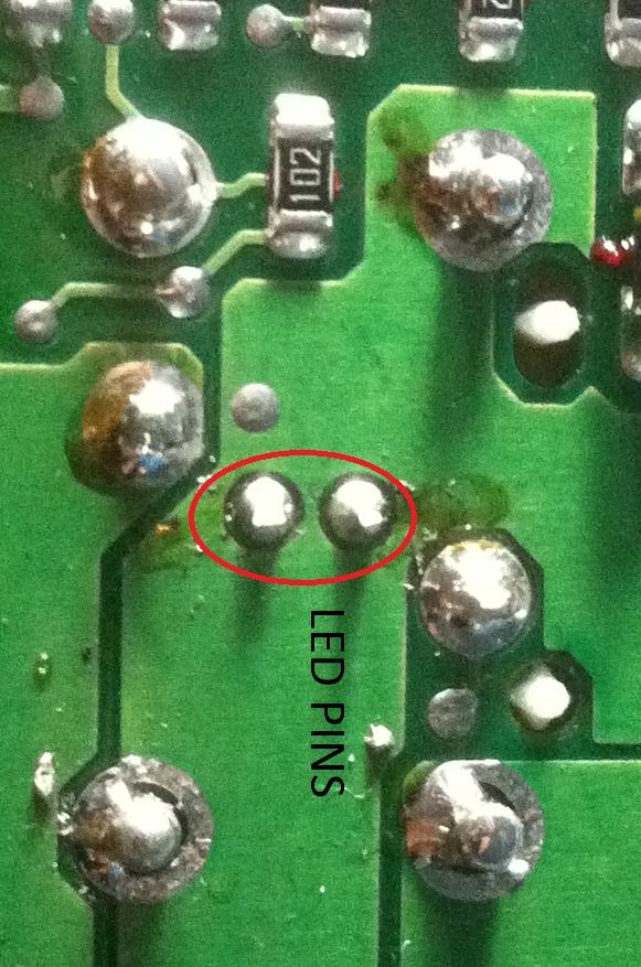
the other 2 pins are on the other side of the board, circled in red.
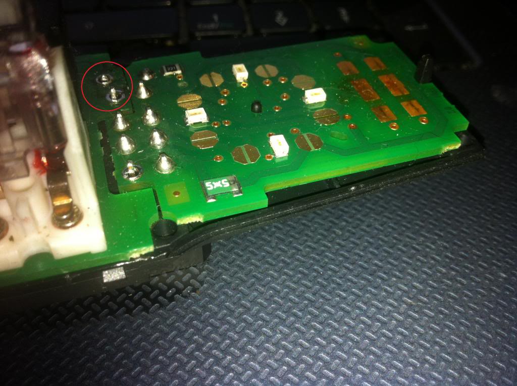
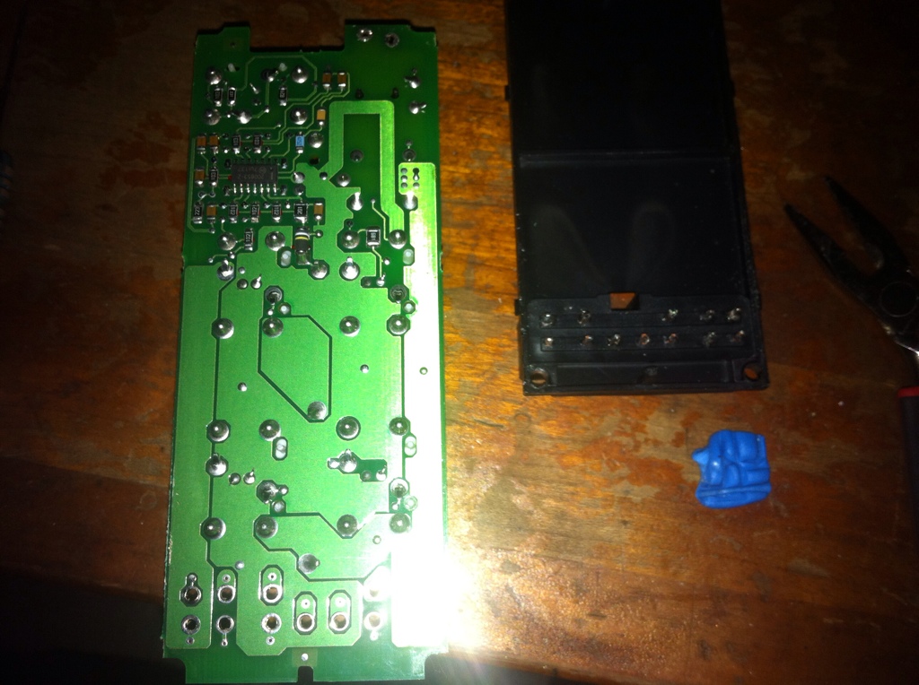
Once that's done you now finally have access to the board in it's entirety.
Step 3:
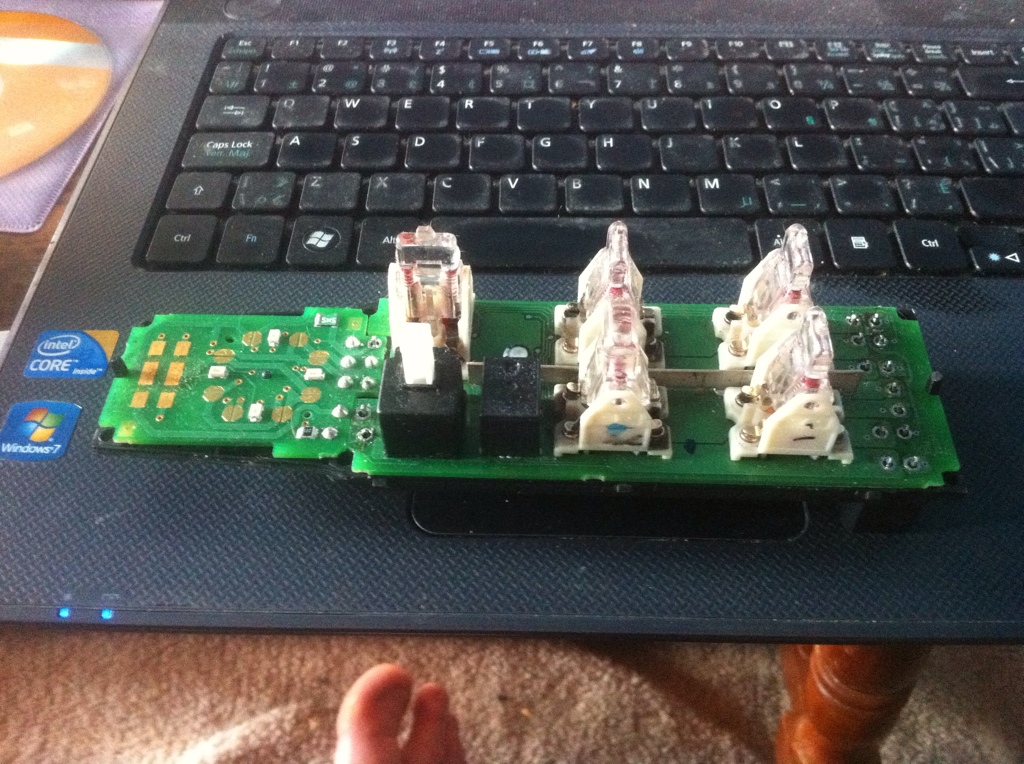
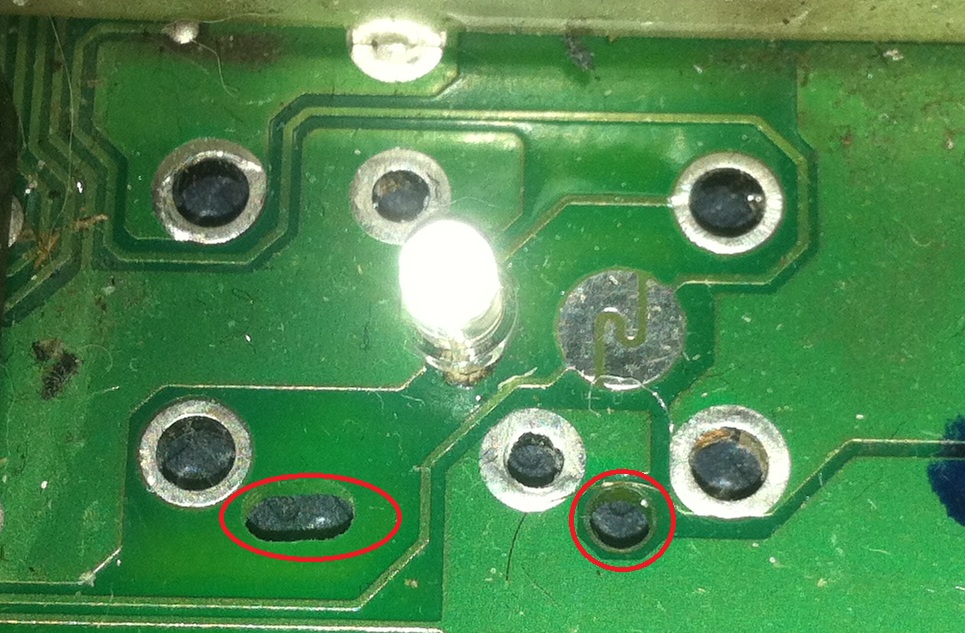
This is where it starts to get really tricky. Now you need to de-solder each of the pins on each switch. There are 6 pins for each switch, and 2 pins for each LED.
Circled in red are the pins for one switch, but they each have the same pattern.
Also of note are the alignment pegs/holes on the switches and PCB respectively.
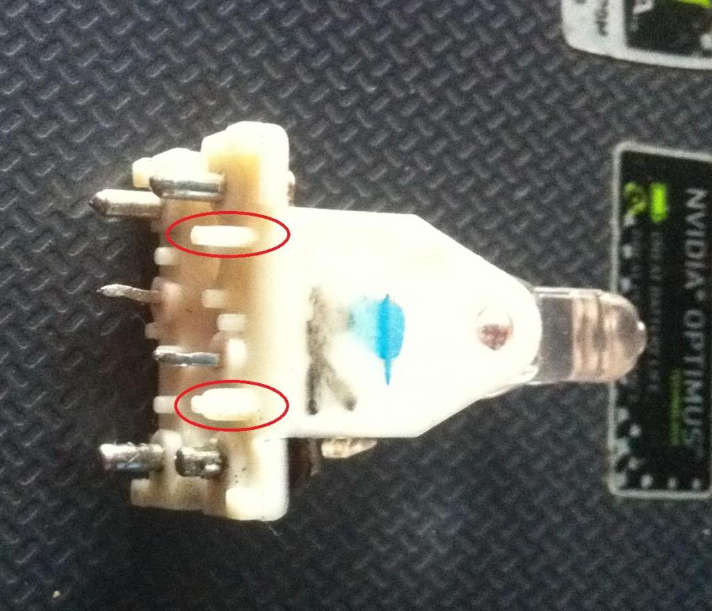
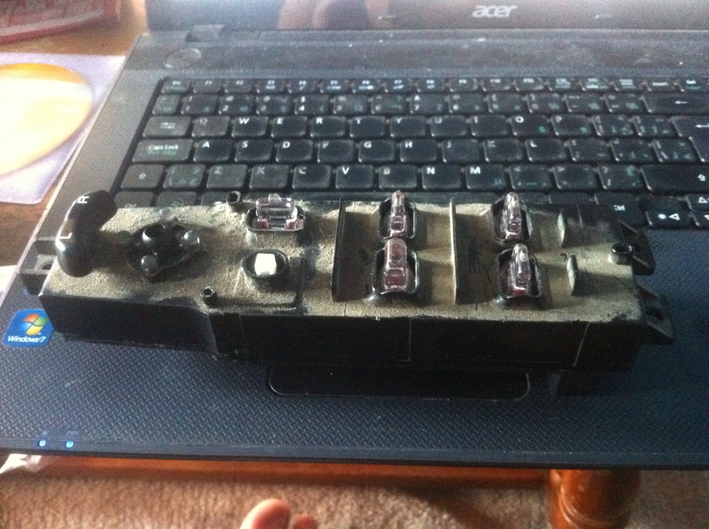
To make de-soldering the switches significantly easier, disassemble the switch BEFORE YOU DE-SOLDER IT. You'll notice the large contact pins will slide out of the switch, if the switch is taken apart.
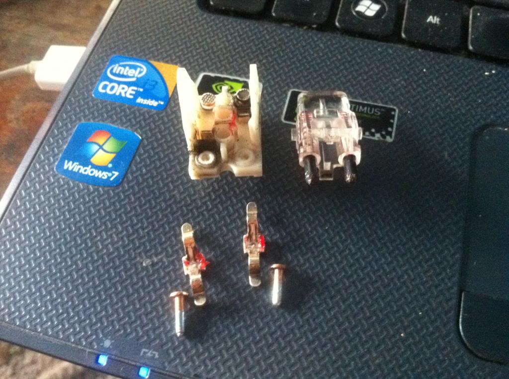
NOTE: On the drivers "auto" window switch there is a paddle that is slightly longer that hits a plunger to activate the auto window feature. Make sure you put this back in the correct spot or your windows will not function correctly and you will need to de-solder all of this again to correct it. Notice the longer protrusion to the left side of the switch in this picture.
Once the switch has been taken apart you can remove the 4 main pins from the board by simply pushing them through with the soldering iron after you have sucked the solder away.
There are still two pins which are bent, to secure the switch to the board. These are the two hardest pins to deal with as they need to be hot before they can be bent back. Even after the solder has been removed they will be stuck to the copper pads, just pulling on them will yank out the pad, the sleeve, and the trace... This is bad.
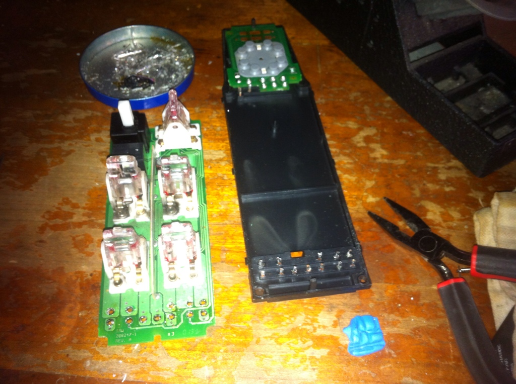
I would suggest taking your time and doing this one switch at a time to avoid confusion. For the purpose of this write-up I'm using a dead board (Yes I destroyed my first one and it cost me $84 to replace) and have all the switches removed.
Once you have removed the switch you now have access to the LED underneath it.
Step 4:
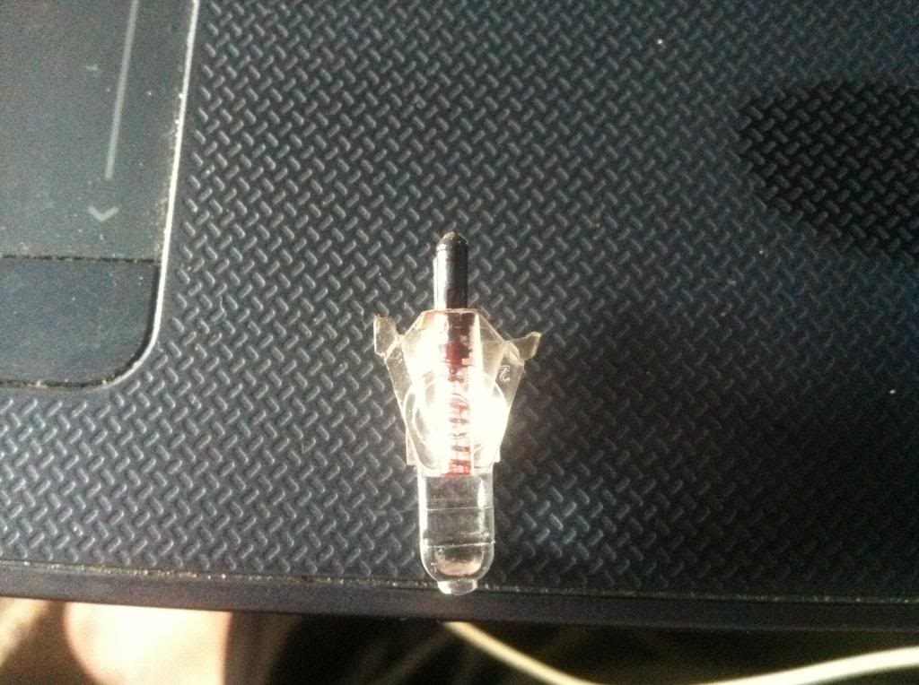
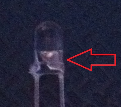
DE-SOLDER THE LEDs CAREFULLY, PAY ATTENTION TO THE BULB. INSIDE IT WILL HAVE A WIDE TRIANGLE PORTION. THIS IS THE CATHODE (Negative) PLACE YOUR LED IN THE BOARD WITH THE SAME ORIENTATION AS THE FACTORY GREEN LED YOU JUST REMOVED, ACCORDING TO THE CATHODE. THIS IS THE EASIEST WAY TO DETERMINE THE CORRECT POLARITY. THERE IS NO EASY WAY TO TEST THE ILLUMINATION UNTIL THE ENTIRE UNIT HAS BEEN COMPLETELY REASSEMBLED. YOU DO NOT WANT TO DO THIS MORE THAN ONCE.
Step 5:
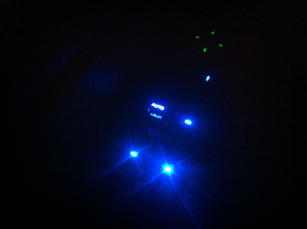
With your new LEDs in place you can now put the switch back in and move on to the next one following the same process.
After all of your switches are complete and YOU HAVE DOUBLE AND TRIPLE CHECKED THAT YOU RE-SOLDERED EACH AND EVERY SWITCH, AND LED PIN, you can put the board back into the housing and re-solder those 14 pins and re-assemble the whole unit.
I haven't gotten to the replacing the mirror LEDs as they are SMDs and I need to buy a more precise soldering iron tip, and I have just recently found replacement bulbs for that job.
This is also the hardest switch panel in the truck to complete. The drivers side, and rear door window switches are far far simpler.
YOU ATTEMPT THIS MOD AT YOUR OWN RISK. IF YOU DO NOT KNOW HOW TO SOLDER, ARE NOT COMFORTABLE WITH IT OR DON'T HAVE THE PROPER TOOLS THEN DO NOT ATTEMPT THIS MOD. A SINGLE MISTAKE WILL CAUSE FUSES TO BLOW, WINDOW FAILURE, LOST MONEY, INJURY AND DEATH TO OCCUR (ok, maybe not death)
I CAN NOT AND WILL NOT BE HELD RESPONSIBLE FOR ANY PROBLEMS ARISING FROM THIS MOD. I'M MERELY PROVIDING THE INFORMATION.
__________________________________________________ __________________________________________________ __________________________________________________ ________________
Tools Needed:
A Cat
Soldering Supplies
Preferably a very expensive re-work station if you happen to have access to one. This lets you heat and remove the solder in one step. Press a button and it sucks the solder off the board through the nozzle.
Small Screwdriver (Flat)
Pliers and Wire Cutters
3mm LEDs
Process:
I won't be covering certain steps such as disassembly, because quite frankly if you are unable to figure out how to take something apart you should not be attempting this mod.
Step 1:
Remove the door switch panel according to the service manuals outlined procedure. This is about the only time you will need the manual because removing the switch panel is all Dodge thinks you need to do.
After it's out and has the bezel removed you will need to pull off the switch covers. This can be tricky as they are secured very well to the switches, but you can pry them off in whatever fashion you decide.
Once all of the covers are removed you can open the housing to gain access to the circuit board.
Step 2:
Dodge was crafty here, and made this job as hard as possible to prevent people from messing with things.
There are 14 pins that need to be de-soldered before the circuit board can be removed, and it's impossible to reach the switch pins without removing the board, unless you cut a square out of the housing, but you're still going to have to solder so there is no point in destroying the housing.
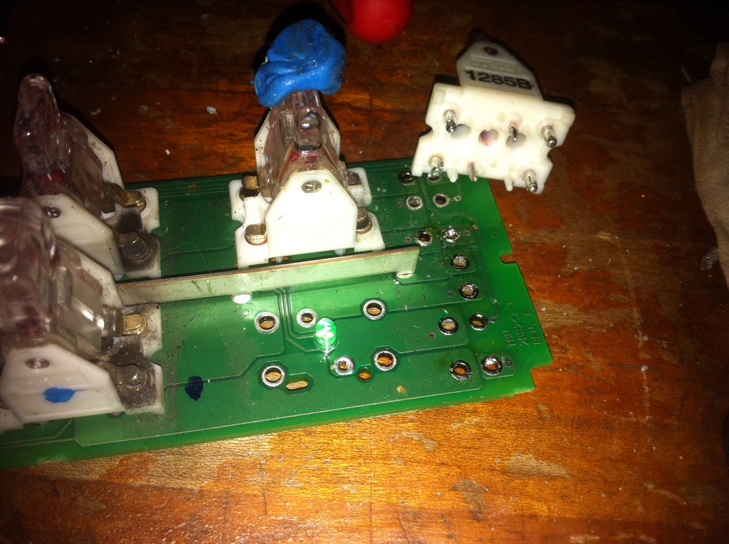
Make sure you have some way to hold the switch assembly secure while you de-solder. I use the blue sticky tack which works fairly well to hold stuff in place.
12 pins located here
the other 2 pins are on the other side of the board, circled in red.
Once that's done you now finally have access to the board in it's entirety.
Step 3:
This is where it starts to get really tricky. Now you need to de-solder each of the pins on each switch. There are 6 pins for each switch, and 2 pins for each LED.
Circled in red are the pins for one switch, but they each have the same pattern.
Also of note are the alignment pegs/holes on the switches and PCB respectively.
To make de-soldering the switches significantly easier, disassemble the switch BEFORE YOU DE-SOLDER IT. You'll notice the large contact pins will slide out of the switch, if the switch is taken apart.
NOTE: On the drivers "auto" window switch there is a paddle that is slightly longer that hits a plunger to activate the auto window feature. Make sure you put this back in the correct spot or your windows will not function correctly and you will need to de-solder all of this again to correct it. Notice the longer protrusion to the left side of the switch in this picture.
Once the switch has been taken apart you can remove the 4 main pins from the board by simply pushing them through with the soldering iron after you have sucked the solder away.
There are still two pins which are bent, to secure the switch to the board. These are the two hardest pins to deal with as they need to be hot before they can be bent back. Even after the solder has been removed they will be stuck to the copper pads, just pulling on them will yank out the pad, the sleeve, and the trace... This is bad.
I would suggest taking your time and doing this one switch at a time to avoid confusion. For the purpose of this write-up I'm using a dead board (Yes I destroyed my first one and it cost me $84 to replace) and have all the switches removed.
Once you have removed the switch you now have access to the LED underneath it.
Step 4:
DE-SOLDER THE LEDs CAREFULLY, PAY ATTENTION TO THE BULB. INSIDE IT WILL HAVE A WIDE TRIANGLE PORTION. THIS IS THE CATHODE (Negative) PLACE YOUR LED IN THE BOARD WITH THE SAME ORIENTATION AS THE FACTORY GREEN LED YOU JUST REMOVED, ACCORDING TO THE CATHODE. THIS IS THE EASIEST WAY TO DETERMINE THE CORRECT POLARITY. THERE IS NO EASY WAY TO TEST THE ILLUMINATION UNTIL THE ENTIRE UNIT HAS BEEN COMPLETELY REASSEMBLED. YOU DO NOT WANT TO DO THIS MORE THAN ONCE.
Step 5:
With your new LEDs in place you can now put the switch back in and move on to the next one following the same process.
After all of your switches are complete and YOU HAVE DOUBLE AND TRIPLE CHECKED THAT YOU RE-SOLDERED EACH AND EVERY SWITCH, AND LED PIN, you can put the board back into the housing and re-solder those 14 pins and re-assemble the whole unit.
I haven't gotten to the replacing the mirror LEDs as they are SMDs and I need to buy a more precise soldering iron tip, and I have just recently found replacement bulbs for that job.
This is also the hardest switch panel in the truck to complete. The drivers side, and rear door window switches are far far simpler.
Last edited by GRNDPNDR; Jan 9, 2013 at 01:00 PM.
I really don't see how this could be done in any easier way. If you don't take the switches out you can't replace the LED's, and it specifically says in the service manual that this is not a serviceable unit and if a light is burned out the entire unit must be replaced.
So this is the only way to either replace a faulty factory LED, or put your own in.
So this is the only way to either replace a faulty factory LED, or put your own in.

It depends on how far you really want to go. I just provided the information for those who want to do it, have the skill to do it, or have been wondering what's involved in doing it.
Yes.... Do have a spare, or do it right the first time 
All Star
Joined: Feb 2011
Posts: 928
Likes: 0
From: South Texas
Very nice sir! I wish I still had access to one of those soldering stations. Alas, my hobbies are already expensive enough as it is LoL
Trending Topics
It can be done without a re-work station, it's just much harder, and mostly because of the huge pins for the switch contacts. That's when I discovered that taking the switches apart make that much much easier.
I don't know if it's an odd wiring issue with my truck or if the PCI BUS is doing something weird but from time to time the illumination on my switch panel goes out, EXCEPT the drivers window switch, it's the only LED that remains illuminated. The other doors are fine.
It happened today for the second time, the first time it happened they came back a while later. Hopefully they come back again, but if someone can help me pin point what the problem might be I'd appreciate it.
No blown fuses, the windows still work, just the lights go out. I haven't been able to identify which pin/wire specifically controls the illumination on these switch panels, so I don't know if it's a loose wire somewhere either.