


DIY: Rebuilding a Trac-Lok LSD

Thread Starter
|
Champion

Joined: May 2008
Posts: 4,839
Likes: 5
From: Apex, NC
By the way hydra, good eye! I'm surprised you saw that.
Hall Of Fame


Joined: Jun 2005
Posts: 14,228
Likes: 19
From: Riverton, UT
I'm an Inspector, I'm paid good money to notice the little things.......LOL
The funny thing is you saw the post before I PM'ed you about it! But then again, I'm finishing up some things on this and also some things in my original thread https://dodgeforum.com/forum/1st-gen...lp-please.html.
I knew what you were doing with your differential and building it in time as well as taking the time to rebuild your complete frame up Dakota. (Good luck to you) The average user does not understand the lubrication components and although I saw this way back when you helped me with this thread I noticed the Lithium grease but as it is on the parts I didn't want the average user to do the same.
Now on the Wheel Seals contact areas to seal and seal lip, and also the pinion seal area and seal lip I applied a small amount of Mobil 1 Fully Synthetic wheel (disk brake and muti-purpose) grease to lubricate them and also to create a non scared seal lip surface while installing the components. To date everything is sealed and functioning as intended as it is supposed to be.
Thanks again 95_318SLT!
Thread Starter
|
Champion
Joined: May 2008
Posts: 4,839
Likes: 5
From: Apex, NC
Actually, it's not lithium grease, its just a multi-purpose high temp grease... same stuff I use to grease my ball joints and tie rods. Brake cleaner should clean it right off of there later.
Thread Starter
|
Champion
Joined: May 2008
Posts: 4,839
Likes: 5
From: Apex, NC
I would like to offer an alternative way to get the spider gears back in during the reassembly that I just found out today may be easier than my previous method.
This is what I had before:
For the new method, follow step 1 as stated, but for step 2:
Step 2) Reinstall the spider gears into the carrier. An extra pair of hands is needed for this method. Start by compressing 1 side of clutches (yes, only 1 side!!) with the bolt. Now, place the spider gears on the side gears like before, making sure they are exactly opposite of each other also as stated before. But this time, do it with the carrier out of the axle housing. Hold the carrier while making sure the spider gears stay seated. Slide an axle shaft into the non-compressed side and have someone turn it. Something still may be needed for leverage (in my case, my dad held it with a crowbar). Keep turning it until the pin will slide through.
DSCN0531.jpg?t=1258848549
DSCN0530.jpg?t=1258848586
And then proceed to step 3 as previously performed.
This is what I had before:
Step 1) Install the side gears and clutch packs in the carrier. Again, make sure the belleville springs are against the side gear concaved outward.
Step 2) Now, the most fun part of the whole project!! Reinstall the spider gears into the carrier. An extra pair of hands will help you out a lot here, but I did it myself so it is possible. You need to place the spider gears on the side gears. VERY IMPORTANT!!! MAKE SURE THEY ARE EXACTLY OPPOSITE OF EACH OTHER!!! A good way to be sure is slide the pin through both. Obviously, you will have to hold the bottom one in place so it won't fall (this is where an extra hand will come in handy).


So once you are sure they are lined up, again use the pin as a stop and start turning the carrier using leverage on the axle, just like it came out. Sorry, I didn't get a picture of this because both my hands were tied up.
So once you get them started into the carrier to where the carrier will hold them, you can let go:

Now you can use both hands to turn the axle and stop when the pin fits through everything.

Step 2) Now, the most fun part of the whole project!! Reinstall the spider gears into the carrier. An extra pair of hands will help you out a lot here, but I did it myself so it is possible. You need to place the spider gears on the side gears. VERY IMPORTANT!!! MAKE SURE THEY ARE EXACTLY OPPOSITE OF EACH OTHER!!! A good way to be sure is slide the pin through both. Obviously, you will have to hold the bottom one in place so it won't fall (this is where an extra hand will come in handy).
So once you are sure they are lined up, again use the pin as a stop and start turning the carrier using leverage on the axle, just like it came out. Sorry, I didn't get a picture of this because both my hands were tied up.
So once you get them started into the carrier to where the carrier will hold them, you can let go:
Now you can use both hands to turn the axle and stop when the pin fits through everything.
Step 2) Reinstall the spider gears into the carrier. An extra pair of hands is needed for this method. Start by compressing 1 side of clutches (yes, only 1 side!!) with the bolt. Now, place the spider gears on the side gears like before, making sure they are exactly opposite of each other also as stated before. But this time, do it with the carrier out of the axle housing. Hold the carrier while making sure the spider gears stay seated. Slide an axle shaft into the non-compressed side and have someone turn it. Something still may be needed for leverage (in my case, my dad held it with a crowbar). Keep turning it until the pin will slide through.
DSCN0531.jpg?t=1258848549
DSCN0530.jpg?t=1258848586
And then proceed to step 3 as previously performed.
Last edited by 95_318SLT; Nov 21, 2009 at 07:13 PM.
Hall Of Fame
Joined: Jun 2005
Posts: 14,228
Likes: 19
From: Riverton, UT
When I did it I got the spiders as tight and up to each side enough that they wouldn't fall out. One bolt was used to compress one side of the cluch packs. Then install it in the axle housing and installed the bearing cap bolts. I then installed a axle into the housing and into the other side of the differential then installed a wheel on the axle. I then used the pin to hold differential from moving and turned the tire slamming it forward to force the spiders back into place. I then removed the tire and axle and removed the differential so that I could replace the bearings on the differential.
Hall Of Fame
Joined: Jun 2005
Posts: 14,228
Likes: 19
From: Riverton, UT
I would like to add some information on gears, ware, and correct gear alignment:
Here is some illustrations of the inside of a differential:

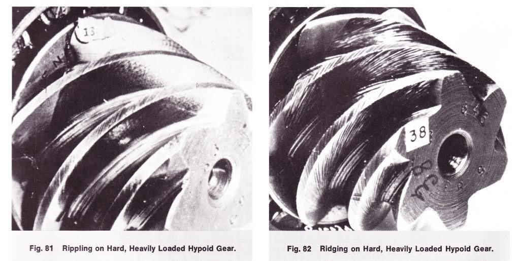
Pinion Gear Ware:
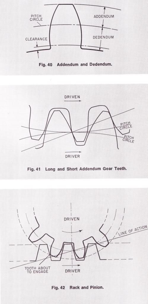
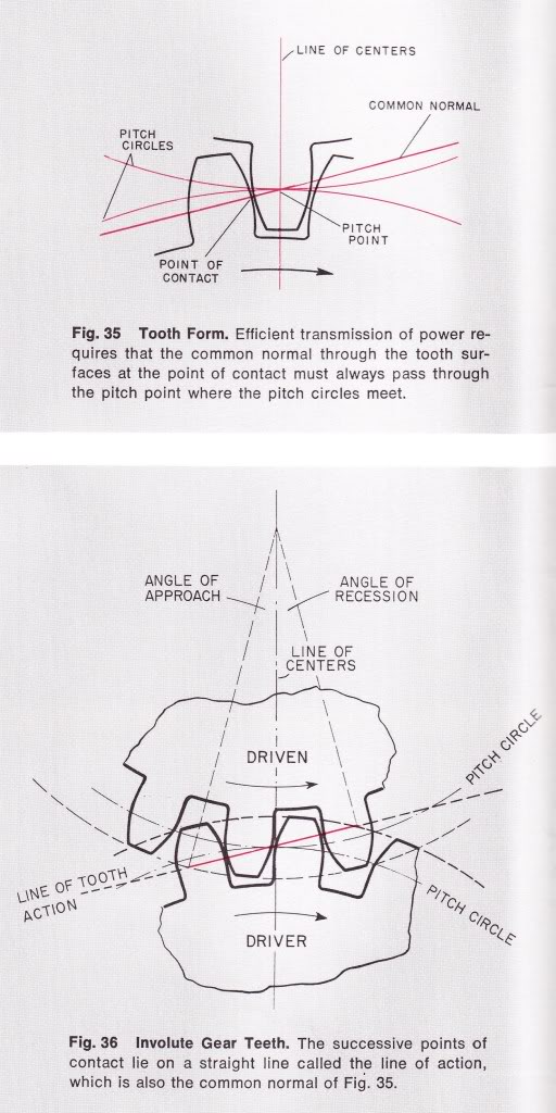
Proper alignment of gear load transfer:
Here is some illustrations of the inside of a differential:
Pinion Gear Ware:
Proper alignment of gear load transfer:
Hall Of Fame
Joined: Jun 2005
Posts: 14,228
Likes: 19
From: Riverton, UT
Here is some Great info provided by 45AutoPete:
http://www.drivetrain.com/parts_cata...tructions.html
And
http://www.ringpinion.com/Content/Ho...structions.pdf
http://www.drivetrain.com/parts_cata...tructions.html
And
http://www.ringpinion.com/Content/Ho...structions.pdf
Last edited by hydrashocker; Mar 20, 2010 at 03:52 PM.