


DIY: Rebuilding a Trac-Lok LSD

Thread Starter
|
Champion

Joined: May 2008
Posts: 4,839
Likes: 5
From: Apex, NC
I'm writing this for Hydrashocker (in case your wondering who this new guy is who doesn't even have a durango :P), but hopefully some more of you guys will get help from it.
READ ALL THE WAY THROUGH BEFORE ATTEMPTING THIS. THIS JOB REQUIRES SPECIFIC TOOLS AND MAY BE OUTSIDE MANY DIYer's COMFORT ZONE!! The rear axle is a very finicky part of the truck and requires a very precise set-up.
First off, I'm using an axle housing that is not yet in my truck, and I've already gone through this process and am now backtracking to write this, so all my parts will look clean and new. Just forgive this fact and pretend its a mess like yours will be! :P
The tool list: (besides the obvious sockets, wrenches, etc.)
> Dial indicator with magnetic base/stand
> Carrier threaded adjuster adjusting tool
> Clutch pack compressing tool
DSCN0500.jpg?t=1257395697
READ ALL THE WAY THROUGH BEFORE ATTEMPTING THIS. THIS JOB REQUIRES SPECIFIC TOOLS AND MAY BE OUTSIDE MANY DIYer's COMFORT ZONE!! The rear axle is a very finicky part of the truck and requires a very precise set-up.
First off, I'm using an axle housing that is not yet in my truck, and I've already gone through this process and am now backtracking to write this, so all my parts will look clean and new. Just forgive this fact and pretend its a mess like yours will be! :P
The tool list: (besides the obvious sockets, wrenches, etc.)
> Dial indicator with magnetic base/stand
> Carrier threaded adjuster adjusting tool
For this, you have some options. You can buy the specific tool made for this job. Just do a google search for "Chrysler 9.25 Spanner tool" or "Chrysler 9.25 threaded adjuster tool." Another option (this is what I used) is to use a dodge dakota (or similar) torsion bar. The hex head on the end of the torsion bar is the right size! (you'll see what I'm talking about later in this thread). Another option is to use a bolt with the right size head. Put a washer on the bolt and a nut behind that, and then use a socket on the nut!
> Inch-Pound AND Foot-Pound torque wrench> Clutch pack compressing tool
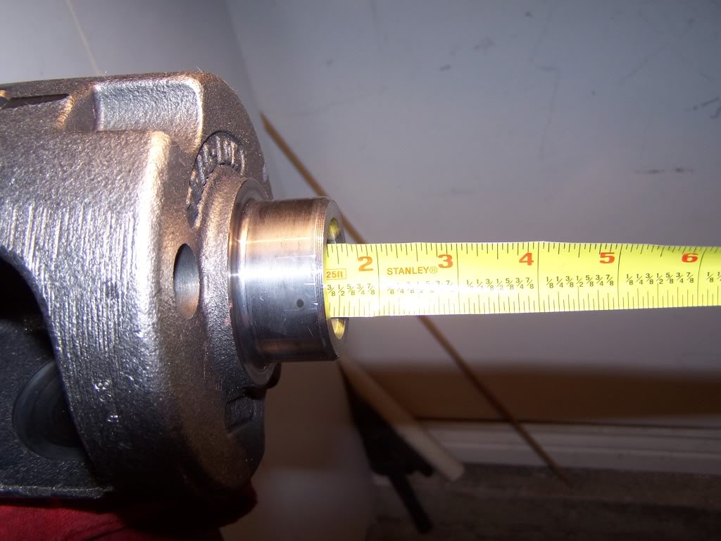
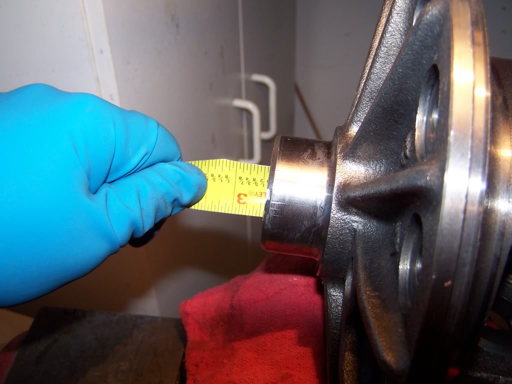
Again, you have some options here. You can do a google search and find the proper tool made for this job, or what I did was go to the hardware store and bought 2 coarse threaded 3/4" by 4.5" bolts, matching nuts, and 4 3/4" ID, 2" OD washers.
(the picture sucks cause of lense distortion, but it really is 4.5" long)DSCN0500.jpg?t=1257395697
Last edited by 95_318SLT; Nov 9, 2009 at 11:33 PM.
Thread Starter
|
Champion
Joined: May 2008
Posts: 4,839
Likes: 5
From: Apex, NC
Step 1) Jack up the rear of the truck, put the axle on jack stands, and remove the rear wheels. Get a oil drain pan and remove the differential cover.
Step 2) Remove the axle shafts. To do this, remove this bolt and pull the center pin out.
(The axle I'm using for this write up was only partially assembled... your carrier will still be in the housing at this point, so forgive the pics)
DSCN0458.jpg?t=1257377065
DSCN0459.jpg?t=1257377201
With that pin out, push in on the axles and let the c-clips drop, then slide the axles out.
Step 3) Remove the carrier from the axle housing. To do this, remove the carrier bearing retainers, and slide the adjuster tool down the axle shaft to back off the threaded adjusters. A torsion bar works great for the tool if you have one or can get it cheaper than the official tool (~$60). It would be smart at this step to count the number of turns each one gets backed off (for example, turn them out 3 turns, or make it an easy to remember integer... don't do say 2 and a partial turn) so when you reinstall it, you can put the adjusters very close to where they came out!!!
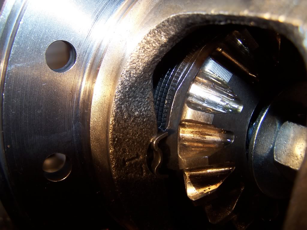
Here is the adjuster (your carrier will still be in place though, so it won't look like this).
DSCN0444.jpg?t=1257377726
This is the torsion bar's fit in the adjuster:
DSCN0445.jpg?t=1257377761
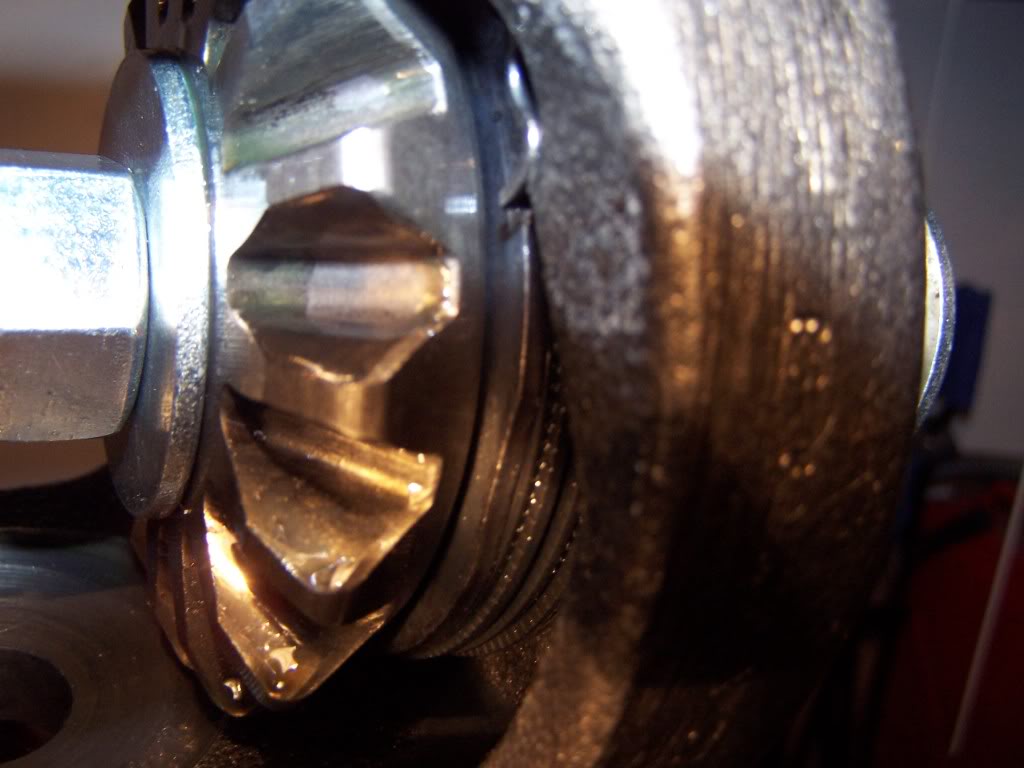
A wider picture of that:
DSCN0446.jpg?t=1257377795
This is what you'll be looking at down the axle tube:
DSCN0447.jpg?t=1257377910
So you should now have this:
DSCN0462.jpg?t=1257377986
Step 4) Remove the spider gear thrust washers. This was the biggest PITA until I figured out a method. The reason is, unlike an open differential that freely turns inside, the LSD does not!
To get the thrust washers out, you'll need to compress the clutches. I used 2 very large bolts, 2 matching nuts, and 4 washers. Dodge makes a special tool to do this, but going to the hardware store and getting bolts is much much cheaper! (these bolts are in the above picture).
The bolts have to go in 1 specific way to both fit, so start by taking one bolt, and pushing it through the ring gear side. When it gets to the middle of the carrier, slide the washer on it and finish pushing it through to the other side, and slide on the other washer and thread on the nut.
DSCN0463.jpg?t=1257378403
DSCN0465.jpg?t=1257378423
Push the other bolt through the same way, but put the washer on it from the start. Slide the other washer and nut on when it's through.
DSCN0466.jpg?t=1257378473
DSCN0467.jpg?t=1257378530
DSCN0468.jpg?t=1257378549
Tighten both down until the spider gears are loose (until you can wiggle them).
DSCN0469.jpg?t=1257378568
These are the thrust washers:
DSCN0470.jpg?t=1257378601
DSCN0471.jpg?t=1257378629
Take a small flathead screwdriver and push the thrust washers out.
DSCN0472.jpg?t=1257378688
With the thrust washers out, remove the clutch compressing bolts.
Step 5) Now, with the thrust washers out, remove the spider gears. To do this, put the carrier back in the housing, and tighten the bearing caps hand tight. Use the center pin to bind up the carrier by placing it part way in the carrier and letting it hit the axle housing. Place it far enough in to be secure, but not far enough to block the spider gears from sliding out.
DSCN0473.jpg?t=1257378717
Next, slide one of the axle shafts in the carrier, and use something for leverage. I used a crowbar inbetween the lugs, or you can use the wheel. It doesnt matter which direction you turn it, but turn it while using the center pin to hold the carrier still. This will force the internals to spin and the spiders will spin out.
DSCN0478.jpg?t=1257378952
DSCN0479.jpg?t=1257379075
Trust me, this is going to be A LOT easier with the worn out clutches than it will be when you put the spiders back in with the new clutches!!!
Step 6) With the spider gears out, pull the axle shafts back out and remove the side gears/clutches. The side gears should come free without a struggle, the clutch's pins are a tight fit in the carrier, so they require some extra motivation.
These are the side gears/clutches:
DSCN0509.jpg?t=1257805739
(Pay attention to how the belleville spring is oriented! Concaved away from the side gear.)
DSCN0506.jpg?t=1257805764
DSCN0507.jpg?t=1257805837
Step 7) Put the new clutch pack together exactly as the old ones are assembled... alternating splined clutch and tabbed clutch with the belleville spring against the side gear concaved away from the gear (the inner diameter up against the gear, the outer diameter up against the next clutch in the pack).
Keep reading for reassembly instructions.
Step 2) Remove the axle shafts. To do this, remove this bolt and pull the center pin out.
(The axle I'm using for this write up was only partially assembled... your carrier will still be in the housing at this point, so forgive the pics)
DSCN0458.jpg?t=1257377065
DSCN0459.jpg?t=1257377201
With that pin out, push in on the axles and let the c-clips drop, then slide the axles out.
Step 3) Remove the carrier from the axle housing. To do this, remove the carrier bearing retainers, and slide the adjuster tool down the axle shaft to back off the threaded adjusters. A torsion bar works great for the tool if you have one or can get it cheaper than the official tool (~$60). It would be smart at this step to count the number of turns each one gets backed off (for example, turn them out 3 turns, or make it an easy to remember integer... don't do say 2 and a partial turn) so when you reinstall it, you can put the adjusters very close to where they came out!!!
Here is the adjuster (your carrier will still be in place though, so it won't look like this).
DSCN0444.jpg?t=1257377726
This is the torsion bar's fit in the adjuster:
DSCN0445.jpg?t=1257377761
A wider picture of that:
DSCN0446.jpg?t=1257377795
This is what you'll be looking at down the axle tube:
DSCN0447.jpg?t=1257377910
So you should now have this:
DSCN0462.jpg?t=1257377986
Step 4) Remove the spider gear thrust washers. This was the biggest PITA until I figured out a method. The reason is, unlike an open differential that freely turns inside, the LSD does not!
To get the thrust washers out, you'll need to compress the clutches. I used 2 very large bolts, 2 matching nuts, and 4 washers. Dodge makes a special tool to do this, but going to the hardware store and getting bolts is much much cheaper! (these bolts are in the above picture).
The bolts have to go in 1 specific way to both fit, so start by taking one bolt, and pushing it through the ring gear side. When it gets to the middle of the carrier, slide the washer on it and finish pushing it through to the other side, and slide on the other washer and thread on the nut.
DSCN0463.jpg?t=1257378403
DSCN0465.jpg?t=1257378423
Push the other bolt through the same way, but put the washer on it from the start. Slide the other washer and nut on when it's through.
DSCN0466.jpg?t=1257378473
DSCN0467.jpg?t=1257378530
DSCN0468.jpg?t=1257378549
Tighten both down until the spider gears are loose (until you can wiggle them).
DSCN0469.jpg?t=1257378568
These are the thrust washers:
DSCN0470.jpg?t=1257378601
DSCN0471.jpg?t=1257378629
Take a small flathead screwdriver and push the thrust washers out.
DSCN0472.jpg?t=1257378688
With the thrust washers out, remove the clutch compressing bolts.
Step 5) Now, with the thrust washers out, remove the spider gears. To do this, put the carrier back in the housing, and tighten the bearing caps hand tight. Use the center pin to bind up the carrier by placing it part way in the carrier and letting it hit the axle housing. Place it far enough in to be secure, but not far enough to block the spider gears from sliding out.
DSCN0473.jpg?t=1257378717
Next, slide one of the axle shafts in the carrier, and use something for leverage. I used a crowbar inbetween the lugs, or you can use the wheel. It doesnt matter which direction you turn it, but turn it while using the center pin to hold the carrier still. This will force the internals to spin and the spiders will spin out.
DSCN0478.jpg?t=1257378952
DSCN0479.jpg?t=1257379075
Trust me, this is going to be A LOT easier with the worn out clutches than it will be when you put the spiders back in with the new clutches!!!
Step 6) With the spider gears out, pull the axle shafts back out and remove the side gears/clutches. The side gears should come free without a struggle, the clutch's pins are a tight fit in the carrier, so they require some extra motivation.
These are the side gears/clutches:
DSCN0509.jpg?t=1257805739
(Pay attention to how the belleville spring is oriented! Concaved away from the side gear.)
DSCN0506.jpg?t=1257805764
DSCN0507.jpg?t=1257805837
Step 7) Put the new clutch pack together exactly as the old ones are assembled... alternating splined clutch and tabbed clutch with the belleville spring against the side gear concaved away from the gear (the inner diameter up against the gear, the outer diameter up against the next clutch in the pack).
Keep reading for reassembly instructions.
Last edited by 95_318SLT; Nov 9, 2009 at 11:15 PM.
Thread Starter
|
Champion
Joined: May 2008
Posts: 4,839
Likes: 5
From: Apex, NC
Well that was the easy part! Now it's time for reassembly. Now you can see what a brand new set of clutches feels like while trying to put the internals back in the carrier!
Step 1) Install the side gears and clutch packs in the carrier. Again, make sure the belleville springs are against the side gear concaved outward.
Step 2) Now, the most fun part of the whole project!! Reinstall the spider gears into the carrier. An extra pair of hands will help you out a lot here, but I did it myself so it is possible. You need to place the spider gears on the side gears. VERY IMPORTANT!!! MAKE SURE THEY ARE EXACTLY OPPOSITE OF EACH OTHER!!! A good way to be sure is slide the pin through both. Obviously, you will have to hold the bottom one in place so it won't fall (this is where an extra hand will come in handy).
DSCN0486.jpg?t=1257388996
DSCN0488.jpg?t=1257389128
So once you are sure they are lined up, again use the pin as a stop and start turning the carrier using leverage on the axle, just like it came out. Sorry, I didn't get a picture of this because both my hands were tied up.
So once you get them started into the carrier to where the carrier will hold them, you can let go:
DSCN0489.jpg?t=1257389151
Now you can use both hands to turn the axle and stop when the pin fits through everything.
DSCN0490.jpg?t=1257389368
Step 3) Installing the thrust washers.
Take the carrier with the newly installed spider gears back out of the housing.
DSCN0491.jpg?t=1257394224
Put the bolts back in the same way as described before to compress the clutches. Tighten them until the spider gears are loose (don't tighten them any more than needed, these are brand new clutches and don't need to be stressed).
With the bolts in, clean the thrust washers thoroughly and put some kind of grease or oil on them. You don't want any dirt on these! Slide the first one in place and hold it in with the pin.
DSCN0492.jpg?t=1257394373
DSCN0493.jpg?t=1257394492
Slide the other side in. I cheated here and used a pin from another differential to hold it in place. Since most people don't keep spare differentials lying around, just do what you can to keep the washer from moving, cause once you release the bolts, the parts cannot be moved!!
DSCN0496.jpg?t=1257394506
DSCN0497.jpg?t=1257394574
And with the bolts out, put the center pin in and tighten the lock bolt. Of course it will have to come out again once the axles go back in, but there are several more steps before then so I went ahead and put it back in place.
DSCN0498.jpg?t=1257394591
DSCN0499.jpg?t=1257394650
(BTW, this is where I was at when I started this. :P Now I have officially gone from making negative progress back to making zero progress!)
Keep reading for setting the backlash on the ring gear and preload on the carrier bearings.
Last edited by 95_318SLT; Nov 9, 2009 at 05:46 PM.
Thread Starter
|
Champion
Joined: May 2008
Posts: 4,839
Likes: 5
From: Apex, NC
Some quick tips for you specifically, hydra (this is due to the blown up sensor and damaged exciter ring):
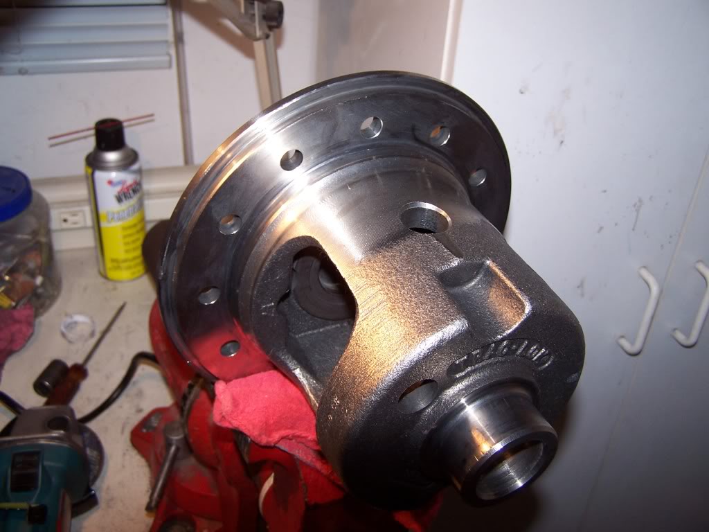
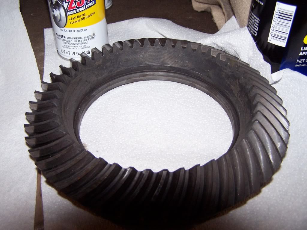
First, save yourself from handling a lot of extra weight and take off the ring gear (as you can see in the pictures, I did this). Since you need to remove it to replace that exciter ring, there's no reason not to as soon as you first get the carrier out. Remember, the ring gear bolts are REVERSE threaded.
Secondly, when you have the carrier all the way apart, use lots of brake cleaner to remove the copper dust and regrease the parts as you put them back together.
Thirdly, when you get ready to swap the exciter gear (and I'm not joking here), put the differential carrier in the oven and heat it up for 10-15 minutes. Take it out of the oven and carefully tap off the exciter gear. Once the carrier is cooled down, put it in the freezer and put the new exciter ring in the oven, and gently tap it onto the carrier. Trust me, the heat makes it very easy!
I would personally swap the exciter ring after the dissasembly process when all you have is an empty carrier with no ring gear on it.
Last edited by 95_318SLT; Nov 9, 2009 at 11:18 PM.
Thread Starter
|
Champion
Joined: May 2008
Posts: 4,839
Likes: 5
From: Apex, NC
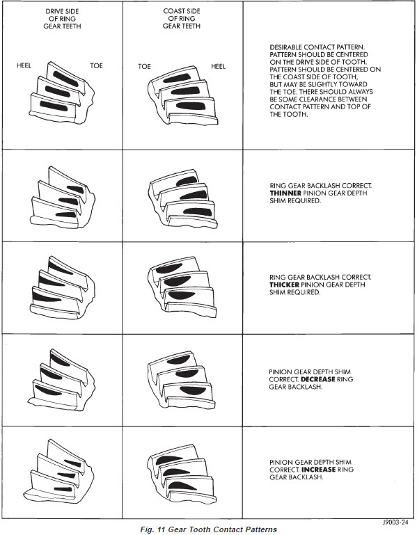
Alright, time to place the carrier! This is part of what scares most people away from axle work, but since the same gear set is being used, and nothing was done to the pinion, there isn't much to it! As long as the backlash is set correctly, the contact pattern will not change and therefore does not need to be checked. But if you want peace of mind, you can check it with gear marking compound when everything is back together and the preload and backlash are both set.
(This picture was taken from the '01 Dakota FSM)
So there are a few things to keep in mind. First, these axles do not use shims for placement, as you have already discovered, they use threaded adjusters. These adjusters push against the bearing sleeve. The jobs of the adjuster are to 1) set the bearing preload to eliminate carrier play and 2) "place" the carrier right and left for setting backlash. Keep in mind... the bearing preload can be fine, but the backlash off, and the backlash can be fine but the bearing preload can be off, so it is a process that could potentially take several tries to get right. In fact, it could easily take a couple hours if you've never done one before, so if you don't have the time or patients, don't even start, cause this is not something to take lightly!!
Step 1) Start by removing the carrier and looking at the adjusters. Make them flush with the carrier housing... this will give you an even starting point for each side.
Step 2) Put the carrier back in and tighten the bearing retainer bolts hand tight using a socket. Turn the pinion gear fast and harshly by hand back and forth several time by half a revolution or so to ensure the ring and pinion are properly meshed and the carrier bearings are fully seated. Retighten the bearing retainer bolts if they are now loose. (You will have to put the transmission and/or transfer case in N to do this, or simply remove the driveshaft from the pinion yoke).
Step 3) Take the adjuster tool (torsion bar in my case), and thread in the adjusters in increments making sure you do both sides evenly! Do this until the carrier is "hand tight" (until you cannot wiggle the carrier right and left). You should lower the increments on each side as you progress to avoid going too far with one side. Now once again, quickly and harshly turn the pinion by hand back and forth like before to seat the bearings (you must do this every time you turn the adjusters, no matter how far they get turned!). Repeat this until everything is good and tight. You should now have a good starting point for an initial measurement.
(This picture was taken from the '01 Dakota FSM)
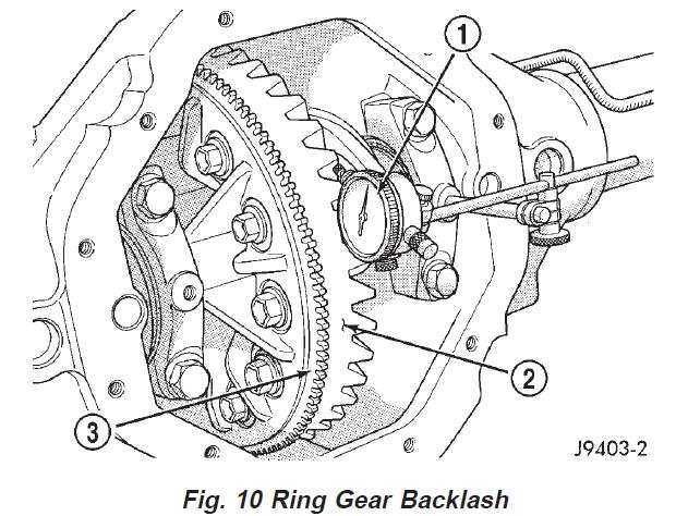
Make sure everything is at least hand tight and there is no play (except for the obvious backlash). With either side of the ring gear's teeth in contact with the pinion gear's teeth, zero the dial indicator. Now rock the ring gear so the other side of the ring gear's teeth are in contact with the pinion gear's teeth and read out how far the dial indicator moved. The inital target is between .003 to .004 inches.
Step 5) Now consider the measurement taken in step 4.
Case 1: If the backlash is on the high side of the inital target (greater than .004"), the carrier needs to be moved closer to the pinion gear.
If this is your case, back off the right (passenger side) adjuster first and then thread in the left (drivers side) adjuster by the same amount, ensuring that the carrier again has no play when you are done. Do this in a very small increment (ever so slight of a turn... keeping in mind that the backlash is in thousandths of an inch!). Once you've done this, rock the pinion back and forth like before to make sure the bearings are seated properly.
Case 2: If the backlash is on the low side of the initial target (below .003"), the carrier needs to be moved away from the pinion gear.
If this is your case, back off the left (drivers side) adjuster first, and then thread in the right (passenger side) by the same amount. Do this in a very small increment (ever so slight of a turn... keeping in mind that the backlash is in thousandths of an inch!). Once you've done this, rock the pinion back and forth like before to make sure the bearings are seated properly.
Now repeat steps 4 and 5 until you have a backlash measurement between .003" and .004".
Step 7) Now take another measurement. If backlash has not yet reached the the specified range, keep tightening the right adjuster until it is. But at this point, each time you turn the right adjuster, loosen the left adjuster by the same amount to keep the preload correct. Remember, each time you turn the adjusters, reseat the bearings before taking a measurement.
When you get the preload set on the bearings, turn the carrier to "feel" how easy it turns, and feel for binding (there shouldn't be any!) Its a good idea before you start to turn the carrier to get a feel for how free it should be.
Step 9) Now tighten the carrier bearing retainer bolts to 100 ft*lbs, and with everything now tight, take one last measurement to ensure the backlash is still between .005" and .008".
If everything is good, put that sucker back together and BE SURE TO INCLUDE 5oz OF FRICTION MODIFIER IN THE 80W-90 GEAR OIL!!! If you choose to use Fully Synthetic still include the Friction Modifier. These Fully Synthetic lubricates are 75W-90 but STILL INCLUDE Friction Modifier even when using Limited Slip rated gear oil.
(This picture was taken from the '01 Dakota FSM)
So there are a few things to keep in mind. First, these axles do not use shims for placement, as you have already discovered, they use threaded adjusters. These adjusters push against the bearing sleeve. The jobs of the adjuster are to 1) set the bearing preload to eliminate carrier play and 2) "place" the carrier right and left for setting backlash. Keep in mind... the bearing preload can be fine, but the backlash off, and the backlash can be fine but the bearing preload can be off, so it is a process that could potentially take several tries to get right. In fact, it could easily take a couple hours if you've never done one before, so if you don't have the time or patients, don't even start, cause this is not something to take lightly!!
Step 1) Start by removing the carrier and looking at the adjusters. Make them flush with the carrier housing... this will give you an even starting point for each side.
Step 2) Put the carrier back in and tighten the bearing retainer bolts hand tight using a socket. Turn the pinion gear fast and harshly by hand back and forth several time by half a revolution or so to ensure the ring and pinion are properly meshed and the carrier bearings are fully seated. Retighten the bearing retainer bolts if they are now loose. (You will have to put the transmission and/or transfer case in N to do this, or simply remove the driveshaft from the pinion yoke).
Step 3) Take the adjuster tool (torsion bar in my case), and thread in the adjusters in increments making sure you do both sides evenly! Do this until the carrier is "hand tight" (until you cannot wiggle the carrier right and left). You should lower the increments on each side as you progress to avoid going too far with one side. Now once again, quickly and harshly turn the pinion by hand back and forth like before to seat the bearings (you must do this every time you turn the adjusters, no matter how far they get turned!). Repeat this until everything is good and tight. You should now have a good starting point for an initial measurement.
You can save yourself some trouble by counting the number of turns you back the carrier off when you FIRST take it out while starting this project and when you put the carrier back in, turn them in the exact same amount. For example, turn each one out 3 turns to release the carrier, and then turn them back in 3 turns during this process. This will give you an even better starting point!
Step 4) Take an initial backlash measurement. To do this, set up your dial indicator as pictured. (This picture was taken from the '01 Dakota FSM)
Make sure everything is at least hand tight and there is no play (except for the obvious backlash). With either side of the ring gear's teeth in contact with the pinion gear's teeth, zero the dial indicator. Now rock the ring gear so the other side of the ring gear's teeth are in contact with the pinion gear's teeth and read out how far the dial indicator moved. The inital target is between .003 to .004 inches.
Step 5) Now consider the measurement taken in step 4.
Case 1: If the backlash is on the high side of the inital target (greater than .004"), the carrier needs to be moved closer to the pinion gear.
If this is your case, back off the right (passenger side) adjuster first and then thread in the left (drivers side) adjuster by the same amount, ensuring that the carrier again has no play when you are done. Do this in a very small increment (ever so slight of a turn... keeping in mind that the backlash is in thousandths of an inch!). Once you've done this, rock the pinion back and forth like before to make sure the bearings are seated properly.
Case 2: If the backlash is on the low side of the initial target (below .003"), the carrier needs to be moved away from the pinion gear.
If this is your case, back off the left (drivers side) adjuster first, and then thread in the right (passenger side) by the same amount. Do this in a very small increment (ever so slight of a turn... keeping in mind that the backlash is in thousandths of an inch!). Once you've done this, rock the pinion back and forth like before to make sure the bearings are seated properly.
Now repeat steps 4 and 5 until you have a backlash measurement between .003" and .004".
Don't get confused, cause factory specifications state to set it between .005" and .008" The idea behind this is initially low setting is the preload still needs to be adjusted, so the adjusters still need to be moved, so moving just the right adjuster in to set the preload will psuh the backlash out.
Step 6) Consider the current backlash measurement. Factory spec is between .005" and .008". Since we are lower than factory spec, the right adjuster needs to be adjusted. This final adjustment is why up until now, everything was to be only hand tightened. For this final adjustment, use a torque wrench on your adjustment tool, thread in the right side adjuster until it reaches 75 ft lbs. Now reseat the bearings by turning the pinion like before. Now repeat this again turning the right side adjuster until you get 75 ft lbs and reseat the bearings. Repeat this until the right side adjuster is at a constant 75 ft lbs (no longer needs to turn to have 75 ft lbs of force on it).Step 7) Now take another measurement. If backlash has not yet reached the the specified range, keep tightening the right adjuster until it is. But at this point, each time you turn the right adjuster, loosen the left adjuster by the same amount to keep the preload correct. Remember, each time you turn the adjusters, reseat the bearings before taking a measurement.
Just a hint, when you tighten the carrier bearing retainers, it will push the carrier slightly toward to the pinion, decreasing the backlash, so when you are setting the final backlash in step 7, go to the high side, like .008" or .009"
Step 8) Now with the backlash in range, use the torque wrench to make sure BOTH adjusters are still at 75 ft lbs. If everything was adjusted precisely, both sides should be close to even and little to no adjusting should be required to reach 75 ft lbs. If the adjusters are considerably off, just start over!When you get the preload set on the bearings, turn the carrier to "feel" how easy it turns, and feel for binding (there shouldn't be any!) Its a good idea before you start to turn the carrier to get a feel for how free it should be.
Step 9) Now tighten the carrier bearing retainer bolts to 100 ft*lbs, and with everything now tight, take one last measurement to ensure the backlash is still between .005" and .008".
If everything is good, put that sucker back together and BE SURE TO INCLUDE 5oz OF FRICTION MODIFIER IN THE 80W-90 GEAR OIL!!! If you choose to use Fully Synthetic still include the Friction Modifier. These Fully Synthetic lubricates are 75W-90 but STILL INCLUDE Friction Modifier even when using Limited Slip rated gear oil.
Last edited by 95_318SLT; Nov 10, 2009 at 06:48 PM.
Thread Starter
|
Champion
Joined: May 2008
Posts: 4,839
Likes: 5
From: Apex, NC
Now that you have done this work, I would suggest you do a test drive with the radio off and listen for any odd noises coming from the axle. Specifically... pay attention to any driveline slap and listen for gear and bearing whine. There shouldn't be any issues if you followed the directions to a T, but its always good to check!
Hall Of Fame


Joined: Jun 2005
Posts: 14,228
Likes: 19
From: Riverton, UT
An extreme thank you is warranted! 
As all have known, I had an issue with my OEM 9.25 Trak-Lok Limited Slip Rear Differential. I have been talking to 95 318SLT via PM in regards to this rebuild. I have decided with the help of 95 to go ahead and do a complete rebuild of the rear end. Pic's will follow!
https://dodgeforum.com/forum/1st-gen-...lp-please.html
Here is the link to show the issue I had and where the problem lye.
I also think that I will add the personal PM's between us to help add to this write up.
Last edited by hydrashocker; Nov 9, 2009 at 03:00 PM.
Trending Topics
Hall Of Fame
Joined: Jun 2005
Posts: 14,228
Likes: 19
From: Riverton, UT
I saw something in the original DIY section that 95_318SLT did when rebuilding his Differential, DO NOT USE GREASE to assemble these differentials. Grease will actually contaminate the gear oil and Friction Modifier thus destroys all your hard work. Only use Hypoid GL-5 rated 80W-90 Gear Oil conventional or 75W-90 Hypoid GL-5 rated Gear Oil Fully Synthetic as lubrication while rebuilding! However, I did in fact use 80W-140 Hypoid GL-5 rated Gear Oil because it was thicker and held onto the all the contact surfaces better. Further, I used Conventional Hypoid GL-5 rated 80W-90 Gear Oil for the fill and will replace the lubricant in 1 month to ensure there is a good flush just in case there are ANY contaminants that were not cleaned out by the rebuild. When I do this I will change over to Mobil 1 75W-90 Fully Synthetic Limited Slip Hypoid Gear Oil and I will add 5oz of Friction Modifier to the diff. I have found this available at $8.99 a Quart at Checkers or Auto Zone and you can buy an 8oz bottle of Friction Modifier at Auto Zone for $4.99. Every other place I know only has 4oz bottles at $8.99!
Now if you install Carbon Fiber clutch packs in replace of the OEM style then you must soak the clutch packs in straight Friction Modifier for at least 20 minutes each, 1 hour is MUCH better.
I wasn't able to get pictures of the full rebuild because of a dead battery but I did get these shots I would like to add.
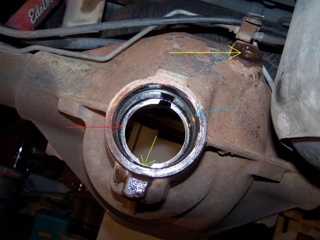
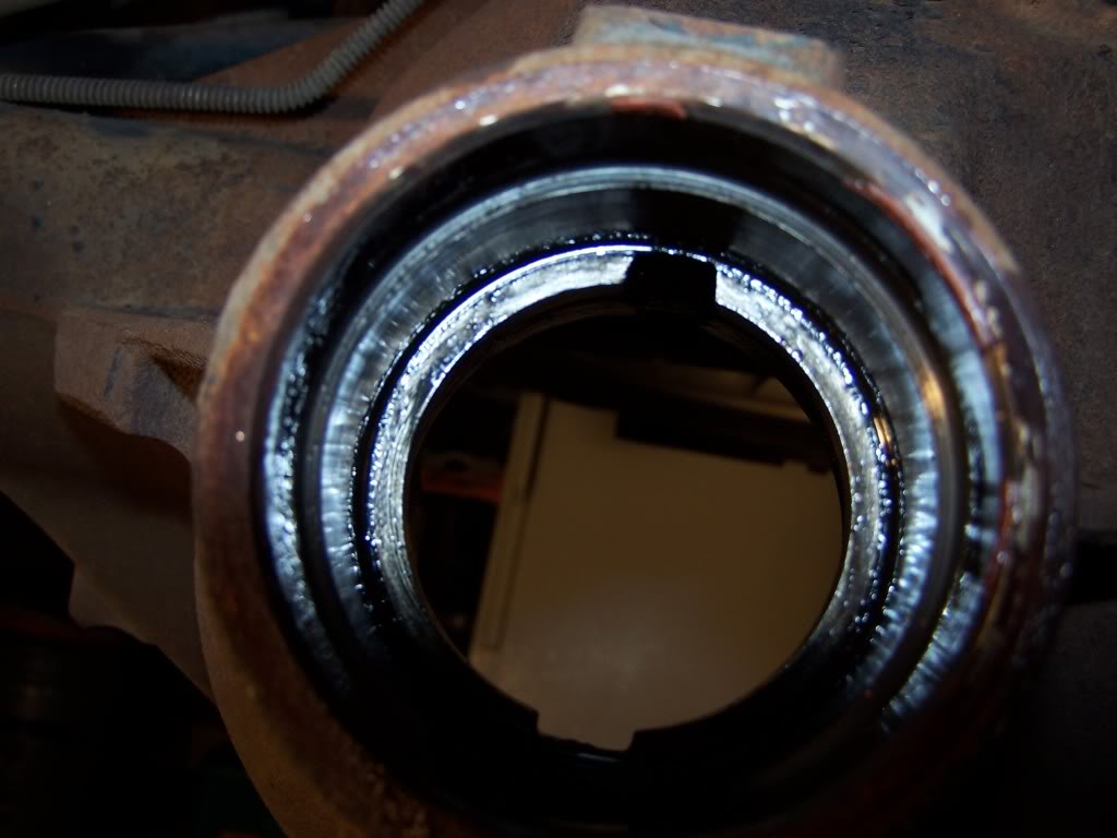
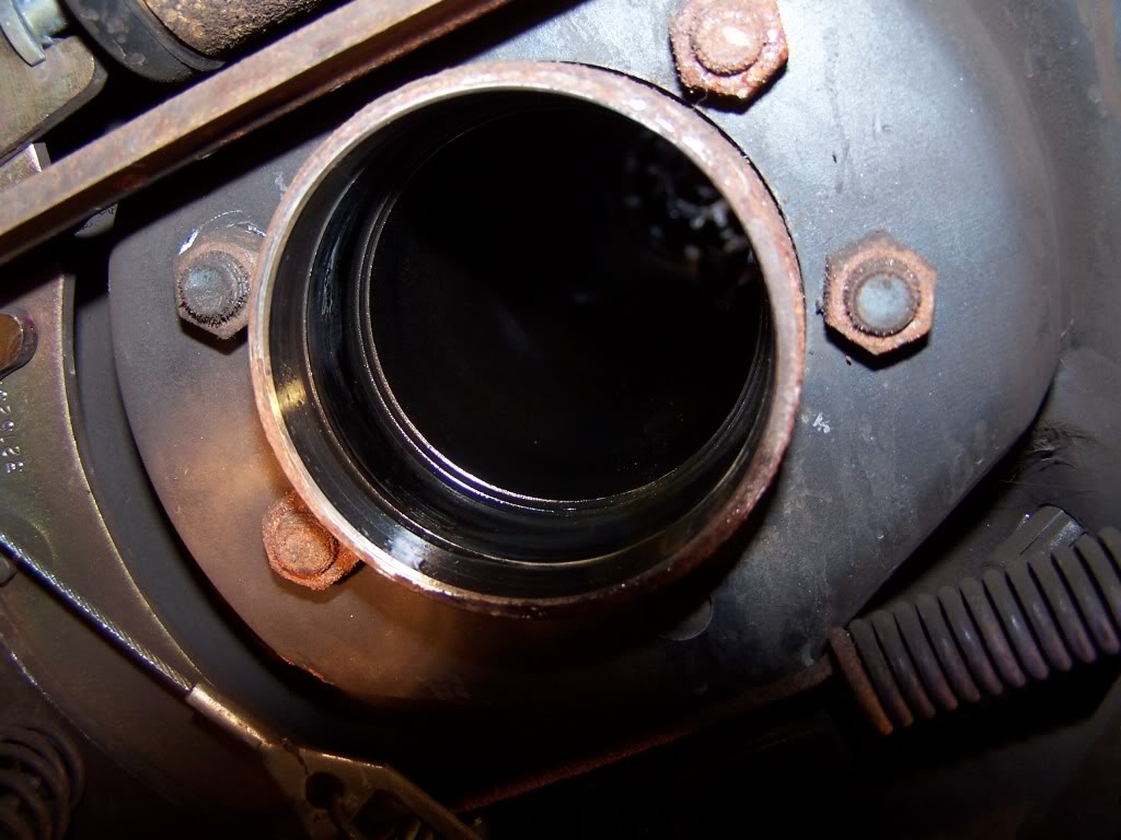
This is a picture looking forward into the axle housing with the differential removed and also the pinion.
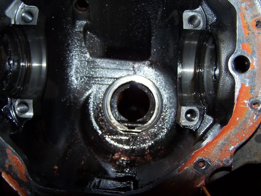
In this picture you can see the bearing race of the larger internal pinion bearing.
Red is the bearing race:
Green is the lubricant sump hole:
that as the differential turns it picks up the lubricant. It then lands on the pinion and gets flung underneath the pinion gear so as the lubricant can access the sump hole and lubricate the large inner bearing. Then it gets flung through the hole that pushes toward the pinion yoke bearing. This is how both bearings get lubricated. Now in this hole is were you are going to find a lot of contamination from ware. You will want to ensure you clean out this sump. I used compressed air to blow everything out.
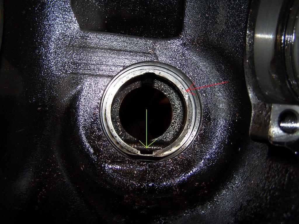
Red is the pinion/yoke bearing race:
Green sump:
Blue is were the yoke seal is located and is shouldered up:
Yellow is the speed/ABS sensor mounting hole:
Here is the DIY for the speed/ABS sensor replacement: https://dodgeforum.com/forum/1st-gen...ensor-diy.html
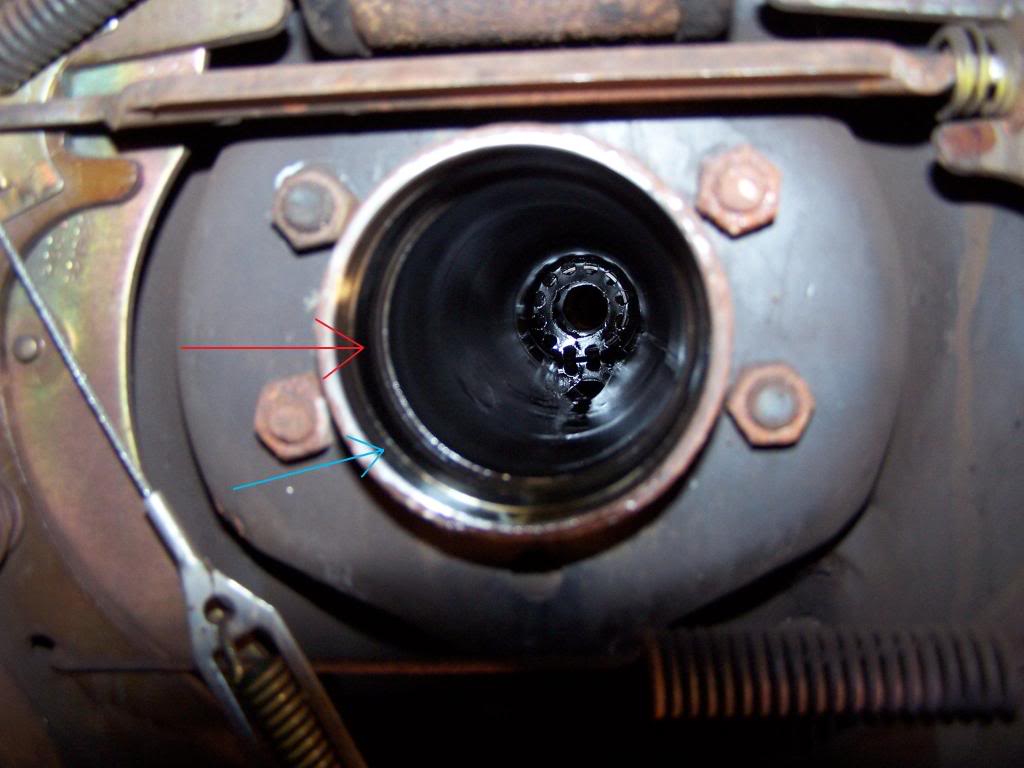
This is looking down the axle tube. You can see the rear brake hardware.
Red is where the wheel bearing is located:
Blue is the wheel seal location:
Parts from Six States http://www.sixstates.com/products/products.jsp
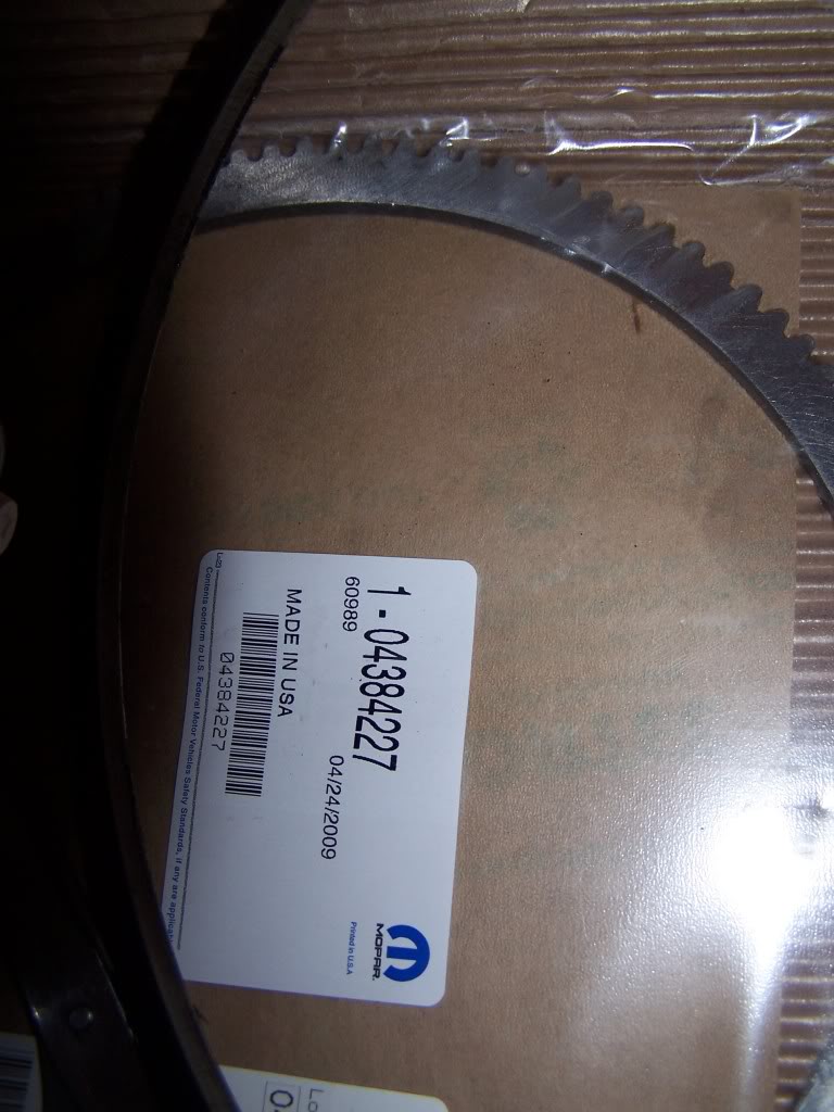
ABS tone ring:
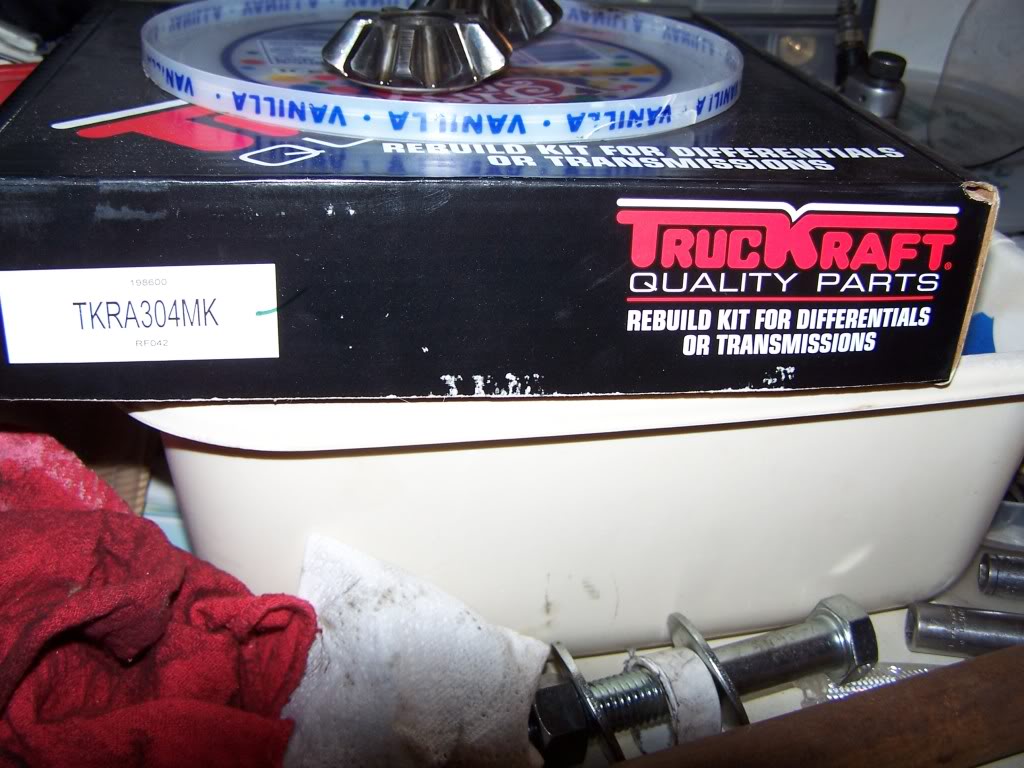
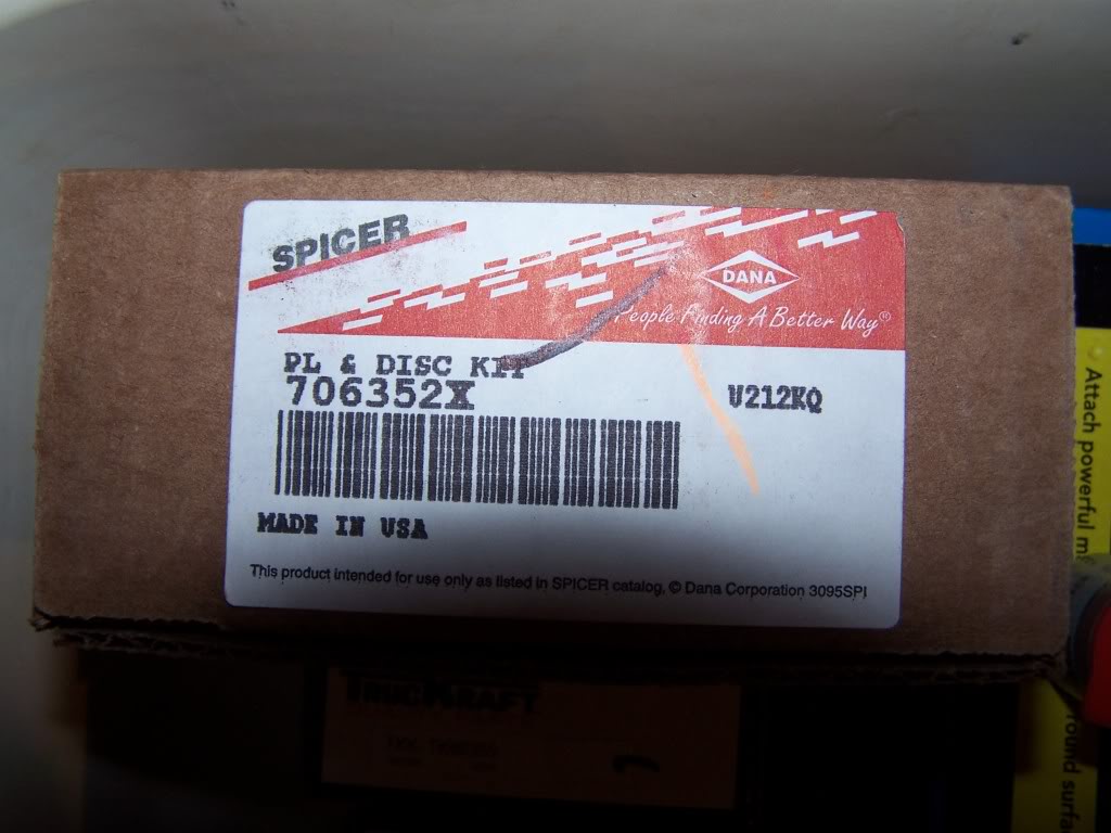
Master Rebuild kit includes differential bearings, pinion bearings (yoke and inner), pinion shims, crush sleeve, and blue RTV gasket sealant. I used copper plus.
Wheel seals.
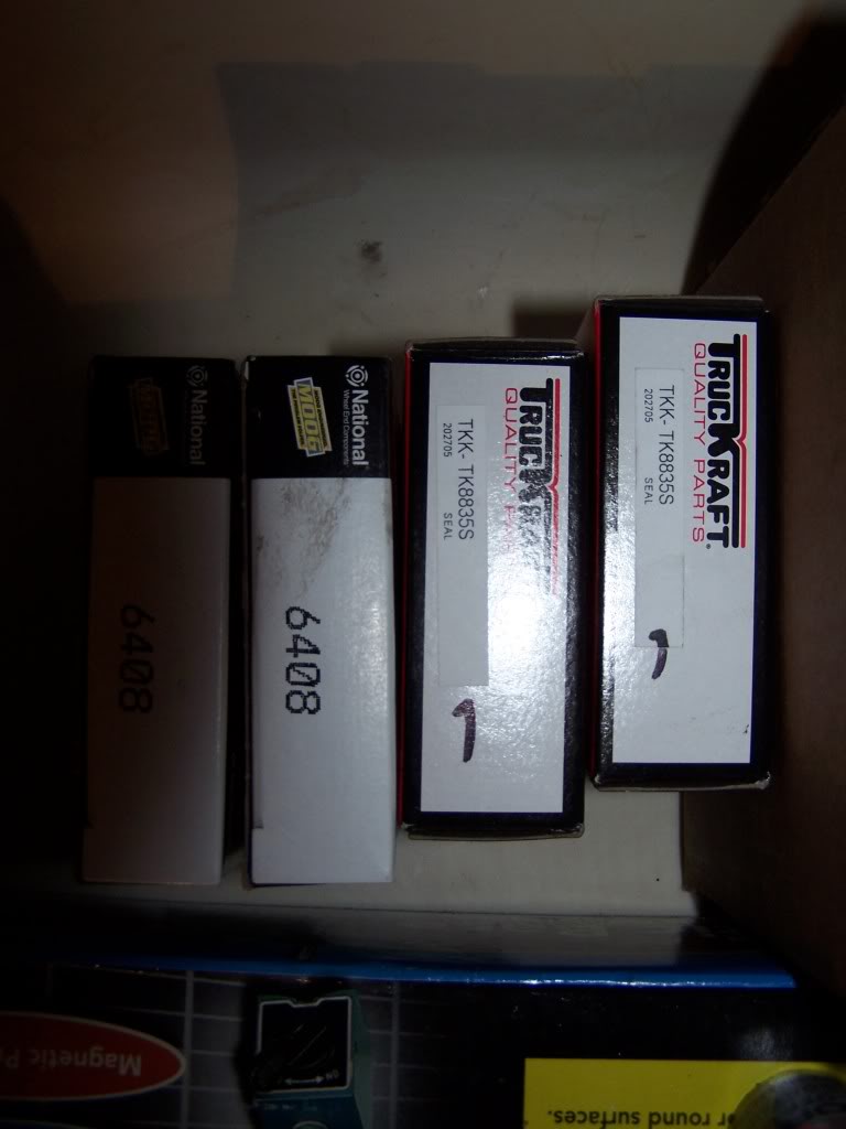
Wheel bearings.
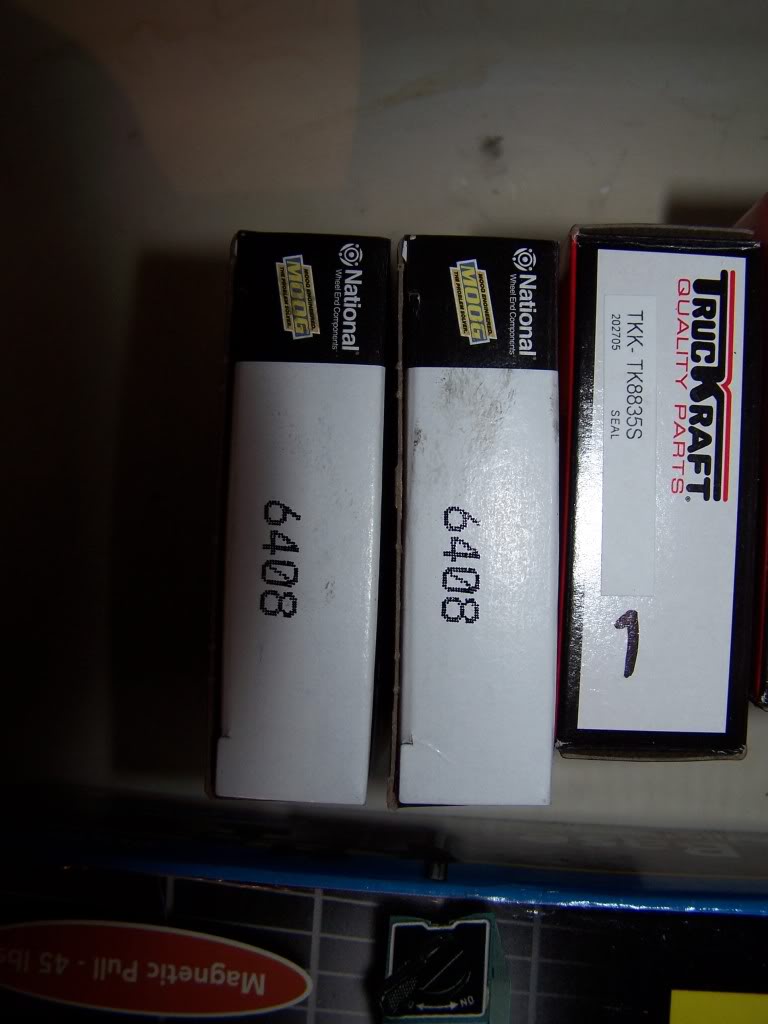
Clutch packs, springs, and clips.
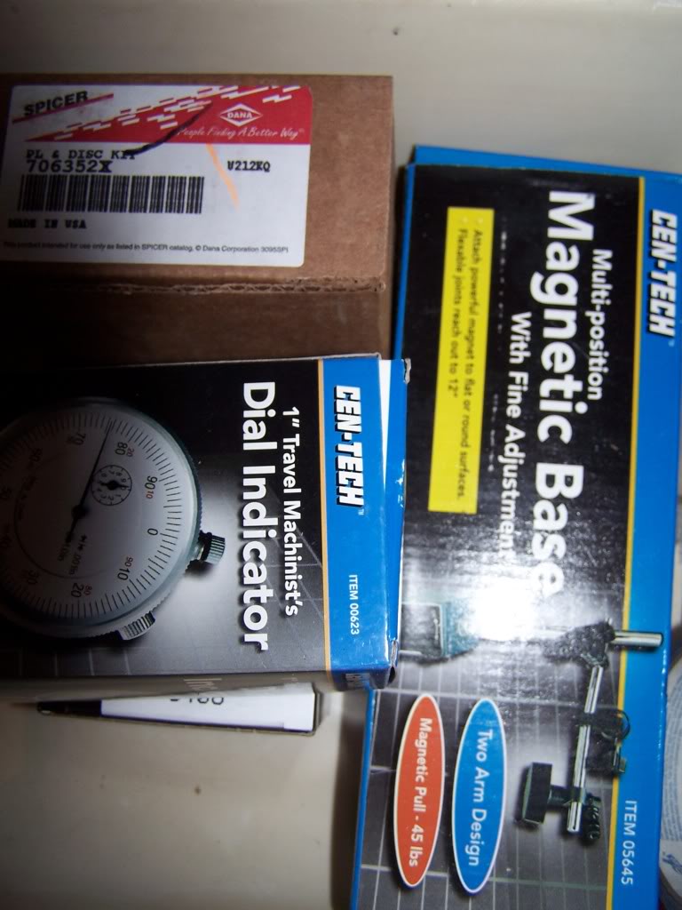
Dial indicator and base from Harbor Freight:
Now if you install Carbon Fiber clutch packs in replace of the OEM style then you must soak the clutch packs in straight Friction Modifier for at least 20 minutes each, 1 hour is MUCH better.
I wasn't able to get pictures of the full rebuild because of a dead battery but I did get these shots I would like to add.
This is a picture looking forward into the axle housing with the differential removed and also the pinion.
In this picture you can see the bearing race of the larger internal pinion bearing.
Red is the bearing race:
Green is the lubricant sump hole:
that as the differential turns it picks up the lubricant. It then lands on the pinion and gets flung underneath the pinion gear so as the lubricant can access the sump hole and lubricate the large inner bearing. Then it gets flung through the hole that pushes toward the pinion yoke bearing. This is how both bearings get lubricated. Now in this hole is were you are going to find a lot of contamination from ware. You will want to ensure you clean out this sump. I used compressed air to blow everything out.
Red is the pinion/yoke bearing race:
Green sump:
Blue is were the yoke seal is located and is shouldered up:
Yellow is the speed/ABS sensor mounting hole:
Here is the DIY for the speed/ABS sensor replacement: https://dodgeforum.com/forum/1st-gen...ensor-diy.html
This is looking down the axle tube. You can see the rear brake hardware.
Red is where the wheel bearing is located:
Blue is the wheel seal location:
Parts from Six States http://www.sixstates.com/products/products.jsp
ABS tone ring:
Master Rebuild kit includes differential bearings, pinion bearings (yoke and inner), pinion shims, crush sleeve, and blue RTV gasket sealant. I used copper plus.
Wheel seals.
Wheel bearings.
Clutch packs, springs, and clips.
Dial indicator and base from Harbor Freight:
Last edited by hydrashocker; Nov 19, 2009 at 02:06 PM.