

ABS module wiring diagram?


Thread Starter
|
Legend


Joined: Feb 2005
Posts: 8,058
Likes: 184
From: Fort Worth, TX
Looking to see if I can use the ABS module as a line-lock for staging, in leu of a transbrake. I have the standard RWAL ABS.
My understanding from the FSM is that the PCM locks the primary solenoid so the pedal can't go any further, the opens the secondary [dump] solenoid for milliseconds at a time to release the rear brakes slowly.
I don't care about having control over the dump solenoid, as long as it stays closed, but I want to be able to open/close the primary solenoid with the flip of a switch [or on the release of a delay box].
The FSM doesn't have any detailed schematics of the ABS system. I know I have to completely unhook the ABS computer for the system to work right, I figure I can get the pigtail from the junkyard and I should have direct access to the solenoids themselves, just have to figure out the operating voltage [5 or 12].
My backup plan is to put a 120 pound-force magnet under the brake pedal, and attach a thick metal plate to the pedal for it to pull against. Just have to figure out how to keep the magnet from pulling away from the floor without any severe drilling.
Last edited by magnethead; Dec 6, 2012 at 02:05 AM.
Thread Starter
|
Legend
Joined: Feb 2005
Posts: 8,058
Likes: 184
From: Fort Worth, TX
Anybody?
From what I can find, there are 2 solenoids and some sort of electronic check valve, all with a common ground, just have to figure out which to energize and de-energize. I figure pull the ABS fuse, then unplug the 4 pin connector for the RWAL contraption and tap into the connector.
From what I can find, there are 2 solenoids and some sort of electronic check valve, all with a common ground, just have to figure out which to energize and de-energize. I figure pull the ABS fuse, then unplug the 4 pin connector for the RWAL contraption and tap into the connector.
Last edited by magnethead; Dec 12, 2012 at 04:41 AM.
Thread Starter
|
Legend
Joined: Feb 2005
Posts: 8,058
Likes: 184
From: Fort Worth, TX
found this - http://www.aa1car.com/library/abs_kelseyhayes_rwal.htm
Looks like I just need to put the common ground where it belongs, and energize the isolation solenoid with the pedal down to lock up the brakes as a line-loc.
As I understand it:
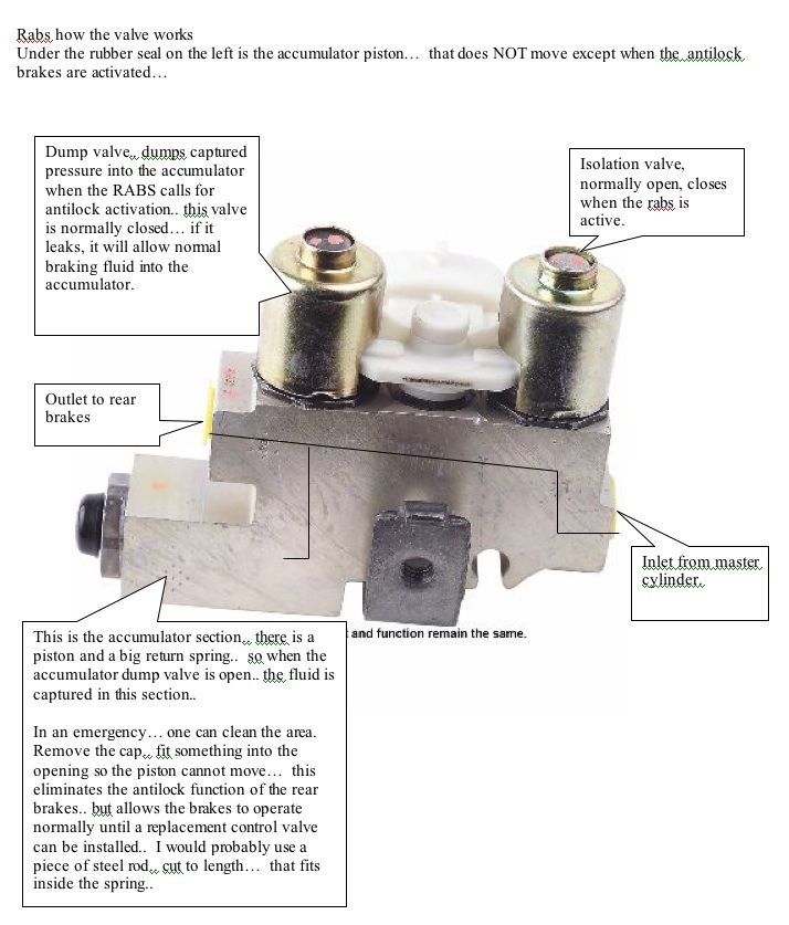
The image shows the system in it's "normal" state. The dump solenoid plunger allows fluid to pass around it, and is only to block/unblock the accumulator. The isolation solenoid is a positive block. With the pedal down and the system in a pressurized state, the isolation plunger is closed (energized), separating the rear brakes from the master cylinder. The dump plunger is then retracted (energized) in a pulsing action, allowing the springs in the brake shoes to push the fluid back through the system, pushing the fluid into the accumulator. When the event has ended, the isolation plunger is retracted (de-energized) then the dump solenoid is closed (de-energized).
So to be a line-loc, I'll want to push the pedal down, energize the isolation solenoid, let go of the pedal, then de-energize the solenoid to go.
I'm hoping I can easily figure out which wire is the common ground just by seeing which wire is shared by both solenoids, and the isolation solenoid is the one on the line from the MC.

Looks like I just need to put the common ground where it belongs, and energize the isolation solenoid with the pedal down to lock up the brakes as a line-loc.
The conventional master brake cylinder and power booster supplies brake pressure to the EH valve, which contains two solenoid valves: a normally open isolation valve to block pressure from the master cylinder to the rear brakes during antilock braking, and a normally closed dump valve for relieving pressure in the rear brake circuits. The EH valve also contains a pressure accumulator for storing fluid pressure during the dump or release phase of operation, and a reset switch which allows the system to maintain proper brake pressure.
When the ABS control module detects a difference in the average speed of the rear wheels compared to the vehicle's overall speed, it initiates antilock braking. The ABS isolation solenoid is energized to prevent any further increase in brake pressure at the rear wheels, and then the ABS dump solenoid valve is opened to release pressure from the rear brake circuits so the wheels can regain speed and traction. Pressure is reapplied when both solenoids are de-energized and return to their normal positions. The cycle is repeated continuously for as long as ABS braking is needed or until the vehicle stops.
When the ABS control module detects a difference in the average speed of the rear wheels compared to the vehicle's overall speed, it initiates antilock braking. The ABS isolation solenoid is energized to prevent any further increase in brake pressure at the rear wheels, and then the ABS dump solenoid valve is opened to release pressure from the rear brake circuits so the wheels can regain speed and traction. Pressure is reapplied when both solenoids are de-energized and return to their normal positions. The cycle is repeated continuously for as long as ABS braking is needed or until the vehicle stops.
The image shows the system in it's "normal" state. The dump solenoid plunger allows fluid to pass around it, and is only to block/unblock the accumulator. The isolation solenoid is a positive block. With the pedal down and the system in a pressurized state, the isolation plunger is closed (energized), separating the rear brakes from the master cylinder. The dump plunger is then retracted (energized) in a pulsing action, allowing the springs in the brake shoes to push the fluid back through the system, pushing the fluid into the accumulator. When the event has ended, the isolation plunger is retracted (de-energized) then the dump solenoid is closed (de-energized).
So to be a line-loc, I'll want to push the pedal down, energize the isolation solenoid, let go of the pedal, then de-energize the solenoid to go.
I'm hoping I can easily figure out which wire is the common ground just by seeing which wire is shared by both solenoids, and the isolation solenoid is the one on the line from the MC.
Last edited by magnethead; Dec 23, 2012 at 05:03 AM.

Thread Starter
|
Legend
Joined: Feb 2005
Posts: 8,058
Likes: 184
From: Fort Worth, TX
Any question can be answered with enough googling. I spent the better part of 6-8 hours looking all this stuff up. But now it's all here for other users to consume.
Thread Starter
|
Legend
Joined: Feb 2005
Posts: 8,058
Likes: 184
From: Fort Worth, TX
Bumping this back up. Looked on my RWAL controller, have Black, blue, white, green. Guessing that black is ground and green is the isolation solenoid that I will want to use for launch.
Just have to figure out how to tap into it. I'd hate to use trailer taps, but I don't know what to look for that would have a mating connector, short of junkyarding another RWAL controller and de-soldering the socket off the circuit board.
Just have to figure out how to tap into it. I'd hate to use trailer taps, but I don't know what to look for that would have a mating connector, short of junkyarding another RWAL controller and de-soldering the socket off the circuit board.
Thread Starter
|
Legend
Joined: Feb 2005
Posts: 8,058
Likes: 184
From: Fort Worth, TX
So, i'm breaking my own rule and pulling this thread from the grave, for a very good reason. this information is not in the FSM nor is it publicized ANYWHERE, accurately, that i could find on the internet.
I picked up a module for $20 at the junkyard, and proceeded to dremel the living crap out of it. It looked like it had been snowing on the workbench.
Alas, the results. I'm still not sure if that sensor is supposed to be grounded or what. That's all that I can figure, but in default state it's not grounded. I'm going to take the pigtail and throw some resistors on it, and see if that makes the CAB happy. Each solenoid is measuring at about 5 ohms.
Both fittings appear to be 1/4" tube with 7/16" inverted flare nuts.
White - solenoid #1 Positive
Blue - center sensor
Black - Both Solenoid common Ground
Green - Solenoid #2 Positive
20161223_113824.jpg
IMG_20161223_122613_082.jpg
Last edited by magnethead; Dec 23, 2016 at 04:11 PM.
Trending Topics
Thread Starter
|
Legend
Joined: Feb 2005
Posts: 8,058
Likes: 184
From: Fort Worth, TX
Side note- the pressure switch on the proportioning valve is grounded when pressurized, open when released. It's an all plastic fitting, not a tapered pipe thread. I don't have a 9/16 socket in the house to bust the sensor out of the RWAL unit, but i'm wondering if it is the same.
Champion


Joined: Jul 2011
Posts: 4,896
Likes: 35
From: Gilbert, Arizona
You sure know how to dig for info thats hardcore
Most auto,s from 2000 on are so complicated and multi computerized you cant do much to them.
But thats the way they want it especially for SMOG
The new direct fuel injection is wild an injector direct to the combustion chamber...what?
Most auto,s from 2000 on are so complicated and multi computerized you cant do much to them.
But thats the way they want it especially for SMOG
The new direct fuel injection is wild an injector direct to the combustion chamber...what?
Thread Starter
|
Legend
Joined: Feb 2005
Posts: 8,058
Likes: 184
From: Fort Worth, TX
You sure know how to dig for info thats hardcore
Most auto,s from 2000 on are so complicated and multi computerized you cant do much to them.
But thats the way they want it especially for SMOG
The new direct fuel injection is wild an injector direct to the combustion chamber...what?
Most auto,s from 2000 on are so complicated and multi computerized you cant do much to them.
But thats the way they want it especially for SMOG
The new direct fuel injection is wild an injector direct to the combustion chamber...what?
Diesels have been direct injection for years. They are just now porting the technology to petrol vehicles. I'm really not sure what took them so long.