

The Official 2nd Gen FAQ and Performance Thread


Thread Starter
|
Grand Champion
Joined: Nov 2005
Posts: 6,258
Likes: 0
From: Charleston, SC
Modification: Tower Strut Bars
Manufacturers: Vibrant, DC Sports, Mopar, “Ebay Brands”
Price Range: $40.00-$330.00
Where to Buy: ModernPerformance.Com, HowellAutomotive.Com, Ebay.Com.
Difficulty of Installation (1 as easiest 10 as most difficult): 1
Time For Installation: 30 minutes
Expected Gains (in WHP): N/A
Explanation of Mod: Tower strut bars are designed to eliminate “flex” in the vehicle chassis. A tower strut bar allows the vehicles suspension and chassis to remain rigid even through high velocity turns. On the Neon, the rear tower strut bar will be more affective than a front bar, however, both are recommended along with upgraded sway bars. *See “Sway Bars” For More Information*
**Installation Instructions**
FRONT and REAR
1). Pop the hood/trunk.
2). Remove the three 13mm nuts.
3). Place strut bar plate over bolts.
4). Replace nuts and tighten strut bar (depending on design).
Thread Starter
|
Grand Champion
Joined: Nov 2005
Posts: 6,258
Likes: 0
From: Charleston, SC
Modification: Sway Bars (a.k.a. “Stabilizer Bars”, “Anti-Roll Bars”, “Anti-Sway bars”)
Manufacturers: Hotchkis, Progress, Eibach, Mopar.
Price Range: $50.00-$400.00
Where to Buy: TitanMotorsports.Com, ModernPerformance.Com, HowellAutomotive.Com.
Difficulty of Installation (1 as easiest 10 as most difficult): 2
Time For Installation: 1 hour – 2 hours
Expected Gains (in WHP): N/A
Explanation of Mod: The sway bars purpose in a vehicles suspension system is to try to keep the car's body from "rolling" in a sharp turn. Reducing body roll is critical because during a sharp turn more weight is applied on the inside tires and less weight on the outside tires, reducing traction dramatically. A sway bar attempts to keep the vehicles body flat by moving force from one side of the body to the other.
[IMG]local://upfiles/24091/2C559A9925C044E0960EF946D5E9DD43.jpg[/IMG]
[IMG]local://upfiles/24091/C777712B711E4B7DBB9DBEFC2C098E33.jpg[/IMG]
**Installation Instructions**
Front
REMOVAL:
1. Raise the vehicle.
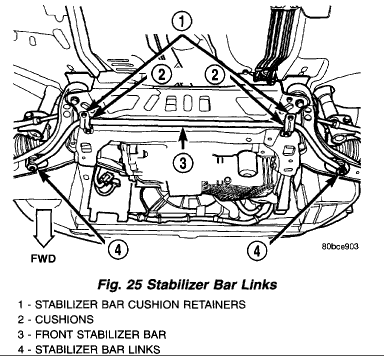
2. Remove both stabilizer bar links from the vehicle. Remove each link by holding the upper retainer/nut with a wrench and turning the link bolt.
3. Remove the stabilizer bar cushion retainer bolts and retainers, and remove the stabilizer bar with cushions attached from the vehicle.
4. To remove the cushions from the stabilizer bar, peel back each cushion at the slit and roll it off the bar.
INSTALLATION
NOTE: Before stabilizer bar installation, inspect the cushions and links for excessive wear, cracks, damage and distortion. Replace any pieces failing inspection.
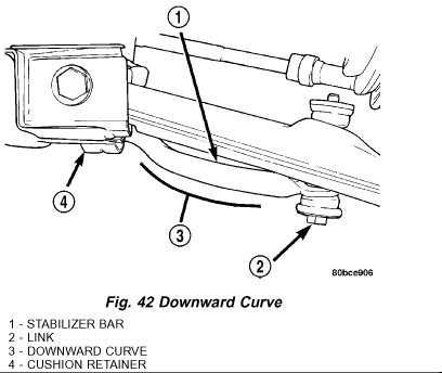
1. If removed, install the stabilizer bar cushions on the stabilizer bar utilizing the slit in each cushion. Position the cushions at each end of the bar's straight beam, just before it begins to curve.
NOTE: Before installing the stabilizer bar, make sure the bar is not upside-down. The stabilizer bar must be installed with the curve on the outboard ends of the bar facing downward to clear the control arms once fully installed.
2. First, place the stabilizer bar in position on the front suspension crossmember. The slits in each cushion must point toward the front of the vehicle and sit directly on top of the raised beads formed into the stamping on the crossmember. Next, install the cushion retainers, matching the raised beads formed into the cushion retainers to the grooves formed into the cushions. Install the cushion retainer bolts, but do not completely tighten them at this time.
3. Install both stabilizer bar links back on vehicle. Start each stabilizer bar link bolt with bushing from the bottom, through the stabilizer bar, inner link bushings, lower control arm, and into the upper retainer/nut and bushing. Do not fully tighten the link assemblies at this time.
4. Lower the vehicle.
NOTE: It may be necessary to put the vehicle on a platform hoist or alignment rack to gain access to the stabilizer bar mounting bolts with the vehicle at curb height.
5. Tighten each stabilizer bar link by holding the upper retainer/nut with a wrench and turning the link bolt. Tighten each link bolt to a torque of 275 inch lbs..
6. Tighten the stabilizer bar cushion retainer bolts to a torque of 250 inch lbs..
Rear
REMOVAL
1. Raise the vehicle.
2. Remove both rear wheel and tire assemblies from the vehicle.
3. Remove the nut from the end of each rear stabilizer bar link bolt. Pull the bolt out through the top of the link and remove the link from each end of the stabilizer bar.
4. Remove the two bolts securing each of the two cushion retainers to the frame
rails, then remove the cushion retainers, cushions and stabilizer bar from the vehicle as an assembly.
5. Pull the cushion retainers off the cushions.
6. The cushions can be removed from the bar by utilizing the pre-formed slit in each cushion and peeling it off the bar.
INSTALLATION
.
1. Install the cushions on the stabilizer bar by opening the slit in the cushion and wrapping the cushion around the bar. When installed properly, the slit in the cushion should face in the same direction as the ends of the stabilizer bar, or toward the front of the car once the bar is installed. The flat side of each cushion should face upward.
2. Install the retainers on the cushions, matching the contour of each retainer with its cushion.
3. Install the stabilizer bar, cushions and retainers on the car as an assembly. The dipped area in the center of the bar must face down to clear the well in the luggage compartment.
4. Install two bolts in each cushion retainer and secure the stabilizer bar to the frame of the vehicle. Do not completely install the bolts at this time.
5. Reinstall each stabilizer bar link:
- Place the link center sleeve and bushings between the eye in the end of the stabilizer bar and the link mounting bracket on the strut.[align=left] - Start the stabilizer bar link bolt with bushing from the top, down through the stabilizer bar,innerlinkbushings and sleeve, and strut link mounting bracket.[/align] - Install a lower bushing, then the nut. Do not tighten the nut at this time.
6. Install both tire and wheel assemblies on the vehicle. Tighten the wheel mounting stud nuts in proper sequence until all nuts are torqued to half specification. Repeat the tightening sequence, this time, to full specified torque of 100 ft. lbs..
7. Lower the vehicle to ground level or curb height.
8. Tighten the rear stabilizer bar cushion retainer bolts to a torque of 300 inch lbs..
9. Tighten the stabilizer bar link nuts to a torque of 200 inch lbs..
10. Set the rear toe on the vehicle to specification if necessary.
Manufacturers: Hotchkis, Progress, Eibach, Mopar.
Price Range: $50.00-$400.00
Where to Buy: TitanMotorsports.Com, ModernPerformance.Com, HowellAutomotive.Com.
Difficulty of Installation (1 as easiest 10 as most difficult): 2
Time For Installation: 1 hour – 2 hours
Expected Gains (in WHP): N/A
Explanation of Mod: The sway bars purpose in a vehicles suspension system is to try to keep the car's body from "rolling" in a sharp turn. Reducing body roll is critical because during a sharp turn more weight is applied on the inside tires and less weight on the outside tires, reducing traction dramatically. A sway bar attempts to keep the vehicles body flat by moving force from one side of the body to the other.
[IMG]local://upfiles/24091/2C559A9925C044E0960EF946D5E9DD43.jpg[/IMG]
[IMG]local://upfiles/24091/C777712B711E4B7DBB9DBEFC2C098E33.jpg[/IMG]
**Installation Instructions**
Front
REMOVAL:
1. Raise the vehicle.
2. Remove both stabilizer bar links from the vehicle. Remove each link by holding the upper retainer/nut with a wrench and turning the link bolt.
3. Remove the stabilizer bar cushion retainer bolts and retainers, and remove the stabilizer bar with cushions attached from the vehicle.
4. To remove the cushions from the stabilizer bar, peel back each cushion at the slit and roll it off the bar.
INSTALLATION
NOTE: Before stabilizer bar installation, inspect the cushions and links for excessive wear, cracks, damage and distortion. Replace any pieces failing inspection.
1. If removed, install the stabilizer bar cushions on the stabilizer bar utilizing the slit in each cushion. Position the cushions at each end of the bar's straight beam, just before it begins to curve.
NOTE: Before installing the stabilizer bar, make sure the bar is not upside-down. The stabilizer bar must be installed with the curve on the outboard ends of the bar facing downward to clear the control arms once fully installed.
2. First, place the stabilizer bar in position on the front suspension crossmember. The slits in each cushion must point toward the front of the vehicle and sit directly on top of the raised beads formed into the stamping on the crossmember. Next, install the cushion retainers, matching the raised beads formed into the cushion retainers to the grooves formed into the cushions. Install the cushion retainer bolts, but do not completely tighten them at this time.
3. Install both stabilizer bar links back on vehicle. Start each stabilizer bar link bolt with bushing from the bottom, through the stabilizer bar, inner link bushings, lower control arm, and into the upper retainer/nut and bushing. Do not fully tighten the link assemblies at this time.
4. Lower the vehicle.
NOTE: It may be necessary to put the vehicle on a platform hoist or alignment rack to gain access to the stabilizer bar mounting bolts with the vehicle at curb height.
5. Tighten each stabilizer bar link by holding the upper retainer/nut with a wrench and turning the link bolt. Tighten each link bolt to a torque of 275 inch lbs..
6. Tighten the stabilizer bar cushion retainer bolts to a torque of 250 inch lbs..
Rear
REMOVAL
1. Raise the vehicle.
2. Remove both rear wheel and tire assemblies from the vehicle.
3. Remove the nut from the end of each rear stabilizer bar link bolt. Pull the bolt out through the top of the link and remove the link from each end of the stabilizer bar.
4. Remove the two bolts securing each of the two cushion retainers to the frame
rails, then remove the cushion retainers, cushions and stabilizer bar from the vehicle as an assembly.
5. Pull the cushion retainers off the cushions.
6. The cushions can be removed from the bar by utilizing the pre-formed slit in each cushion and peeling it off the bar.
INSTALLATION
.
1. Install the cushions on the stabilizer bar by opening the slit in the cushion and wrapping the cushion around the bar. When installed properly, the slit in the cushion should face in the same direction as the ends of the stabilizer bar, or toward the front of the car once the bar is installed. The flat side of each cushion should face upward.
2. Install the retainers on the cushions, matching the contour of each retainer with its cushion.
3. Install the stabilizer bar, cushions and retainers on the car as an assembly. The dipped area in the center of the bar must face down to clear the well in the luggage compartment.
4. Install two bolts in each cushion retainer and secure the stabilizer bar to the frame of the vehicle. Do not completely install the bolts at this time.
5. Reinstall each stabilizer bar link:
- Place the link center sleeve and bushings between the eye in the end of the stabilizer bar and the link mounting bracket on the strut.[align=left] - Start the stabilizer bar link bolt with bushing from the top, down through the stabilizer bar,innerlinkbushings and sleeve, and strut link mounting bracket.[/align] - Install a lower bushing, then the nut. Do not tighten the nut at this time.
6. Install both tire and wheel assemblies on the vehicle. Tighten the wheel mounting stud nuts in proper sequence until all nuts are torqued to half specification. Repeat the tightening sequence, this time, to full specified torque of 100 ft. lbs..
7. Lower the vehicle to ground level or curb height.
8. Tighten the rear stabilizer bar cushion retainer bolts to a torque of 300 inch lbs..
9. Tighten the stabilizer bar link nuts to a torque of 200 inch lbs..
10. Set the rear toe on the vehicle to specification if necessary.
Thread Starter
|
Grand Champion
Joined: Nov 2005
Posts: 6,258
Likes: 0
From: Charleston, SC
Modification: Short Throw Shifter Assembly
Manufacturers: Mopar, Mopure, Maddog.
Price Range: $100.00-$150.00
Where to Buy: DodgeParts.Com, Ebay.Com, Midwestneons.com/Maddog.html
Difficulty of Installation (1 as easiest 10 as most difficult): 1
Time For Installation: 30 minutes – 1 hour
Expected Gains (in WHP): N/A
Explanation of Mod: This modification will reduce the overall throw of each shift but up to 80% over stock giving much quicker shifts. (Mopar = 30% reduction, Mopure = 50% reduction, Maddog = 50%-80% reduction)
(NOTE - Any "rod style" short throw shifter, such as the B&M, only shortens the shifter throw right to left, not front to back. The shifter assemblies described above reduce the throw in every direction anywhere from 30%-80%.)
**Installation Instructions Below**
[hr]
Modification: Shifter/Transmission Bushings (Booger Bushings).
Manufacturers: N/A
Price Range: $25.00
Where to Buy: ModernPerformance.Com, HowellAutomotive.Com.
Difficulty of Installation (1 as easiest 10 as most difficult): 1
Time For Installation: 30 minutes – 1 hour
Expected Gains (in WHP): N/A
Explanation of Mod: These solid bushings will reduce the endplay in the shifter linkage giving crisper, more solid shifting over the stock rubber bushings.
**Installation Instructions**
Short Throw Shifter Assembly and Shifter Bushings:
1. Park car in fourth gear and pull e-brake up as far as possible…remove shifter **** as well.
2. Remove center console (4 bolts in compartment, 2 in lower cup holders). Pull up from back and work it off.
3. Pop off stock shift bushings (2) on either side of the assembly (they are small, round, and black.) They are stuck on the linkage pins and might be tough to get off…remove them off as safely as possible.
4. Remove shift linkage clips. NOTE: This process can be VERY difficult. Use vice-grips or something with a ton of grip. The clips are located between the linkage and the assembly toward the front of the car. Grab a hold of them and pull away from assembly, don’t be afraid to use a lot of force because they are on there very tight!.
5 a. Pop off linkage (use some force and be careful not to break anything). I.E. Pull from strong points of the linkage.
5 b. The assembly should now be free from the linkage. Move it to the side and unbolt and remove the stock assembly (4 corners, 4 nuts). Be sure to keep track of the nuts (and save the old bushings unless they’re totally worn out or you’re installing new bushings).
6. Drop the new assembly into place and lightly tighten the nuts to hold it in while you wrestle with it.
7. Pop the linkage back in (this will be much easier than getting them out), and get those linkage clips back in nice and tight!
8. Get those fresh boogers (or stockers if you didn’t buy new Booger Bushings), and get a finger of grease from the joint of the shaft/assembly and apply it to the linkage pin. Slide the bushings in and make sure they’re in GOOD.
9. Bolt the assembly down nice and tight. Check to make sure the shifts are clean and correct. They should be VERY tight and have almost zero play (if the bushings cause it to be sticky, just let it wear in for a week or two and things will feel much less sticky).
TRANNY BUSHINGS:
1. Take out stock air box (if you have a CAI installed you don’t need to touch it)
2. Disconnect battery (if you haven’t already). 3. Remove battery by loosening the release clamp behind and in front of the battery/tray.
4. Remove battery and tray (lots of small bolts/nuts)
5. Access the bushings (2 ) and remove them just like the shifter bushings, except one is bigger than the other three.
---Be sure to use grease if possible to get the pins in there smooth.
6. DOUBLE CHECK!!!
7. Reassemble.
Thread Starter
|
Grand Champion
Joined: Nov 2005
Posts: 6,258
Likes: 0
From: Charleston, SC
Modification: Suspension Lowering Springs
Manufacturers: Eibach, Goldline, Progress, TEIN, Mopar, Vogtland.
Price Range: $100.00-$220.00
Where to Buy: ModernPerformance.com, HowellAutomotive.Com, Ebay.com, Eibach.Com, Local Wheel/Tire Shop.
Difficulty of Installation (1 as easiest 10 as most difficult): 3.5
Time For Installation:1.5 hours - 3 hours
Expected Gains (in WHP): N/A
Explanation of Mod: Suspension lowering springs have many functions, most of all, they lower the cars center of gravity decreasing body roll which will increase handling capability. Aftermarket lowering springs are genrally shorter, and much more stiff compared to the stock springs. Lowering also gives the Neon a more aggressive stance and cleaner look by eliminating the "4x4" stance stock springs provide Be warned however, that installing lowering springs of any kind onto stock struts will increase stress on the strut shaft causing premature failure of the strut.
[hr]
Modification: Struts
Manufacturers: Tokico, KYB.
Price Range: $200.00-$300.00
Where to Buy: Ebay.com, Local Tire/Wheel/Suspension Shop.
Difficulty of Installation (1 as easiest 10 as most difficult): 3.5
Time For Installation: 1.5 hours -4 hours
Expected Gains (in WHP): N/A
Explanation of Mod:
**Removal and Installation Of Struts**
REMOVAL - STRUT ASSEMBLY (FRONT)
1. Raise the vehicle.
2. Remove tire and wheel assembly from location on front of vehicle requiring strut removal.
3. If both strut assemblies are to be removed, mark the strut assemblies right or left according to which side of the vehicle they were removed from
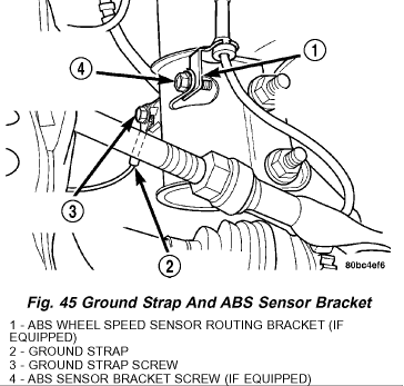
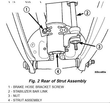
4. Remove the screw securing the ground strap to the rear of the strut.
5. If the vehicle is equipped with Antilock brakes (ABS) , remove the screw securing the ABS wheel speed sensor to the rear of the strut.
CAUTION: The strut assembly-to-steering knuckle attaching bolts are serrated and must not be turned during removal. Hold the bolts stationary in the steering knuckle while removing the nuts, then tap the bolts out using a pin punch.
6. Remove the two bolts attaching the strut to the steering knuckle.
7. Lower the vehicle just enough to open the hood, but without letting the tires touch the floor.
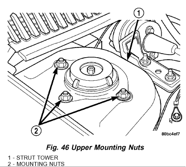
8. Remove the three nuts attaching the upper mount of the strut assembly to the vehicle's strut tower.
9. Remove the strut assembly from the vehicle.
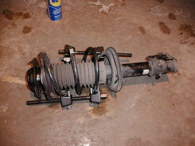
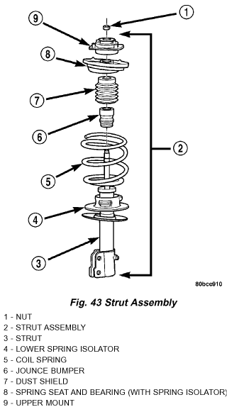
DISASSEMBLY - STRUT ASSEMBLY (FRONT)
The Strut assembly must be removed from the vehicle for it to be disassembled and assembled.
For the disassembly and assembly of the strut assembly, use strut spring compressor, or the equivalent, to compress the coil spring. Follow the manufacturer's instructions closely.
1. If both struts are being serviced at the same time, mark the coil spring and strut assembly according to which side of the vehicle the strut was removed from, and which strut the coil spring was removed from.
2. Position the spring compressors as shown below.
WARNING: DO NOT REMOVE THE STRUT SHAFT NUT BEFORE THE COIL SPRING IS COMPRESSED. THE COIL SPRING IS HELD UNDER PRESSURE AND MUST BE COMPRESSED, REMOVING SPRING TENSION FROM THE UPPER MOUNT AND PIVOT BEARING, BEFORE THE SHAFT NUT IS REMOVED.
3. Compress the coil spring until all coil spring tension is removed from the upper mount.
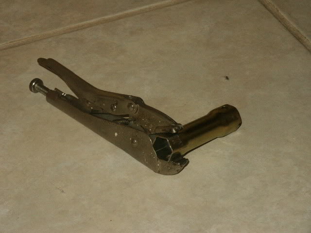
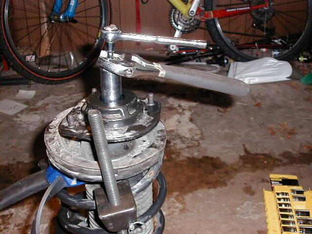
4. Once the spring is sufficiently compressed, install the custom tool shown below on the strut shaft retaining nut. Next, install a 10mm socket with extension on the hex on the end of the strut shaft. While holding the strut shaft from turning, remove the nut from the strut shaft.
(Pictures is a pair of vice-grips and a tractor spark plug socket)
(Pictured below is a 21mm 1/2" drive deepwell socket with a 10mm socket and extension)
5. Remove the upper mount from the strut shaft.
6. Remove the upper spring seat and bearing, along with the upper spring isolator as an assembly from the top of the coil spring by pulling them straight up. The upper spring isolator can be separated from the spring seat and bearing once removed from vehicle.
7. Remove the dust shield, then the jounce bumper from the strut shaft by pulling each straight up.
8. Remove the clamp from the bottom of the coil spring and remove the strut out through the bottom of the coil spring.
9. Remove the lower spring isolator from the lower spring seat on the strut.
ASSEMBLY - STRUT ASSEMBLY (FRONT)
For the disassembly and assembly of the strut assembly, use strut spring compressor, available for rental or purchase at any autoparts store.
1. Place the coil spring in the compressor following the manufacturers instructions. Before compressing the spring, rotate the spring so the end of the top coil is directly in the back as shown.
2. Slowly compress the coil spring until enough room is available for strut assembly reassembly.
3. Install the lower spring isolator on the lower spring seat of the strut.
4. Install the strut through the bottom of the coil spring until the lower spring seat contacts the lower end of the coil spring. Rotate the strut as necessary until the clevis bracket is positioned straight outward away from the compressor. Install the clamp on the lower end of the coil spring and strut, so the strut is held in place.
5. Install the jounce bumper on the strut shaft. The jounce bumper is to be installed with the smaller end pointing downward toward the lower seat.
6. Install the dust shield on the strut shaft. The bottom of the dust shield will snap past the retainer on top of the strut housing.
7. If disassembled, reinstall the upper spring isolator on the upper spring seat and bearing.
8. Install the upper spring seat and bearing on top of the coil spring. Position the notch formed into the edge of the upper seat straight out away from the compressor.
9. Install the strut upper mount over the strut shaft and onto the top of the upper spring seat and bearing.
10. Loosely install the retaining nut on the strut shaft. While holding the strut shaft from turning, tighten the strut shaft retaining nut to a torque of 55 ft. lbs..
11. Slowly release the tension from the coil spring by backing off the compressor drive completely. As the tension is relieved, make sure the upper mount and seat and bearing align properly. Verify the upper mount does not bind.
12. Remove the clamp from the lower end of the coil spring and strut. Push back the spring compressor upper and lower hooks, then remove the strut assembly from the spring compressor.
13. Install the strut assembly on the vehicle.
INSTALLATION - STRUT ASSEMBLY (FRONT)
1. Install the strut assembly into the strut tower, aligning the three studs on the strut upper mount with the holes in strut tower. Install the three mounting nuts on the studs. Tighten the three nuts to a torque of 300 inch lbs..
2. Close the hood of the vehicle.
CAUTION: The strut assembly-to-steering knuckle attaching bolts are serrated and must not be turned during installation. Install the nuts while holding the bolts stationary in the steering knuckle.
3. Position the lower end of the strut assembly in line with the upper end of the steering knuckle and align the mounting holes. Install the two attaching bolts. The bolts should be installed with so that the nuts face towards the front of the vehicle once installed. Install the nuts. Holding the bolts in place tighten the nuts to a torque of 40 ft. lbs. plus an additional 90°turn after the specified torque is met.
4. If the vehicle is equipped with Antilock brakes (ABS) , attach the ABS wheel speed sensor to the rear of the strut (rearward ear) using its mounting screw. Tighten the mounting screw to a torque of 120 inch lbs.
5. Attach the ground strap to the rear of the strut (forward ear) using its mounting screw. Tighten the mounting screw to a torque of 120 inch lbs.
6. Install the tire and wheel assembly. Install and tighten the wheel mounting nuts in proper sequence until all nuts are torqued to half specification. Repeat the tightening sequence to the full specified torque of 100 ft. lbs.
7. Lower the vehicle.
Manufacturers: Eibach, Goldline, Progress, TEIN, Mopar, Vogtland.
Price Range: $100.00-$220.00
Where to Buy: ModernPerformance.com, HowellAutomotive.Com, Ebay.com, Eibach.Com, Local Wheel/Tire Shop.
Difficulty of Installation (1 as easiest 10 as most difficult): 3.5
Time For Installation:1.5 hours - 3 hours
Expected Gains (in WHP): N/A
Explanation of Mod: Suspension lowering springs have many functions, most of all, they lower the cars center of gravity decreasing body roll which will increase handling capability. Aftermarket lowering springs are genrally shorter, and much more stiff compared to the stock springs. Lowering also gives the Neon a more aggressive stance and cleaner look by eliminating the "4x4" stance stock springs provide Be warned however, that installing lowering springs of any kind onto stock struts will increase stress on the strut shaft causing premature failure of the strut.
[hr]
Modification: Struts
Manufacturers: Tokico, KYB.
Price Range: $200.00-$300.00
Where to Buy: Ebay.com, Local Tire/Wheel/Suspension Shop.
Difficulty of Installation (1 as easiest 10 as most difficult): 3.5
Time For Installation: 1.5 hours -4 hours
Expected Gains (in WHP): N/A
Explanation of Mod:
**Removal and Installation Of Struts**
REMOVAL - STRUT ASSEMBLY (FRONT)
1. Raise the vehicle.
2. Remove tire and wheel assembly from location on front of vehicle requiring strut removal.
3. If both strut assemblies are to be removed, mark the strut assemblies right or left according to which side of the vehicle they were removed from
4. Remove the screw securing the ground strap to the rear of the strut.
5. If the vehicle is equipped with Antilock brakes (ABS) , remove the screw securing the ABS wheel speed sensor to the rear of the strut.
CAUTION: The strut assembly-to-steering knuckle attaching bolts are serrated and must not be turned during removal. Hold the bolts stationary in the steering knuckle while removing the nuts, then tap the bolts out using a pin punch.
6. Remove the two bolts attaching the strut to the steering knuckle.
7. Lower the vehicle just enough to open the hood, but without letting the tires touch the floor.
8. Remove the three nuts attaching the upper mount of the strut assembly to the vehicle's strut tower.
9. Remove the strut assembly from the vehicle.
DISASSEMBLY - STRUT ASSEMBLY (FRONT)
The Strut assembly must be removed from the vehicle for it to be disassembled and assembled.
For the disassembly and assembly of the strut assembly, use strut spring compressor, or the equivalent, to compress the coil spring. Follow the manufacturer's instructions closely.
1. If both struts are being serviced at the same time, mark the coil spring and strut assembly according to which side of the vehicle the strut was removed from, and which strut the coil spring was removed from.
2. Position the spring compressors as shown below.
WARNING: DO NOT REMOVE THE STRUT SHAFT NUT BEFORE THE COIL SPRING IS COMPRESSED. THE COIL SPRING IS HELD UNDER PRESSURE AND MUST BE COMPRESSED, REMOVING SPRING TENSION FROM THE UPPER MOUNT AND PIVOT BEARING, BEFORE THE SHAFT NUT IS REMOVED.
3. Compress the coil spring until all coil spring tension is removed from the upper mount.
4. Once the spring is sufficiently compressed, install the custom tool shown below on the strut shaft retaining nut. Next, install a 10mm socket with extension on the hex on the end of the strut shaft. While holding the strut shaft from turning, remove the nut from the strut shaft.
(Pictures is a pair of vice-grips and a tractor spark plug socket)
(Pictured below is a 21mm 1/2" drive deepwell socket with a 10mm socket and extension)
5. Remove the upper mount from the strut shaft.
6. Remove the upper spring seat and bearing, along with the upper spring isolator as an assembly from the top of the coil spring by pulling them straight up. The upper spring isolator can be separated from the spring seat and bearing once removed from vehicle.
7. Remove the dust shield, then the jounce bumper from the strut shaft by pulling each straight up.
8. Remove the clamp from the bottom of the coil spring and remove the strut out through the bottom of the coil spring.
9. Remove the lower spring isolator from the lower spring seat on the strut.
ASSEMBLY - STRUT ASSEMBLY (FRONT)
For the disassembly and assembly of the strut assembly, use strut spring compressor, available for rental or purchase at any autoparts store.
1. Place the coil spring in the compressor following the manufacturers instructions. Before compressing the spring, rotate the spring so the end of the top coil is directly in the back as shown.
2. Slowly compress the coil spring until enough room is available for strut assembly reassembly.
3. Install the lower spring isolator on the lower spring seat of the strut.
4. Install the strut through the bottom of the coil spring until the lower spring seat contacts the lower end of the coil spring. Rotate the strut as necessary until the clevis bracket is positioned straight outward away from the compressor. Install the clamp on the lower end of the coil spring and strut, so the strut is held in place.
5. Install the jounce bumper on the strut shaft. The jounce bumper is to be installed with the smaller end pointing downward toward the lower seat.
6. Install the dust shield on the strut shaft. The bottom of the dust shield will snap past the retainer on top of the strut housing.
7. If disassembled, reinstall the upper spring isolator on the upper spring seat and bearing.
8. Install the upper spring seat and bearing on top of the coil spring. Position the notch formed into the edge of the upper seat straight out away from the compressor.
9. Install the strut upper mount over the strut shaft and onto the top of the upper spring seat and bearing.
10. Loosely install the retaining nut on the strut shaft. While holding the strut shaft from turning, tighten the strut shaft retaining nut to a torque of 55 ft. lbs..
11. Slowly release the tension from the coil spring by backing off the compressor drive completely. As the tension is relieved, make sure the upper mount and seat and bearing align properly. Verify the upper mount does not bind.
12. Remove the clamp from the lower end of the coil spring and strut. Push back the spring compressor upper and lower hooks, then remove the strut assembly from the spring compressor.
13. Install the strut assembly on the vehicle.
INSTALLATION - STRUT ASSEMBLY (FRONT)
1. Install the strut assembly into the strut tower, aligning the three studs on the strut upper mount with the holes in strut tower. Install the three mounting nuts on the studs. Tighten the three nuts to a torque of 300 inch lbs..
2. Close the hood of the vehicle.
CAUTION: The strut assembly-to-steering knuckle attaching bolts are serrated and must not be turned during installation. Install the nuts while holding the bolts stationary in the steering knuckle.
3. Position the lower end of the strut assembly in line with the upper end of the steering knuckle and align the mounting holes. Install the two attaching bolts. The bolts should be installed with so that the nuts face towards the front of the vehicle once installed. Install the nuts. Holding the bolts in place tighten the nuts to a torque of 40 ft. lbs. plus an additional 90°turn after the specified torque is met.
4. If the vehicle is equipped with Antilock brakes (ABS) , attach the ABS wheel speed sensor to the rear of the strut (rearward ear) using its mounting screw. Tighten the mounting screw to a torque of 120 inch lbs.
5. Attach the ground strap to the rear of the strut (forward ear) using its mounting screw. Tighten the mounting screw to a torque of 120 inch lbs.
6. Install the tire and wheel assembly. Install and tighten the wheel mounting nuts in proper sequence until all nuts are torqued to half specification. Repeat the tightening sequence to the full specified torque of 100 ft. lbs.
7. Lower the vehicle.

New Member
Joined: Sep 2008
Posts: 1
Likes: 0
Would getting higher flowing fuel injectors help the horsepower. Because i have a 2001 SE with an intake and I sometimes wonder if the mixture is too lean by the way its really dawgy at times.
Record Breaker
Joined: Jan 2008
Posts: 1,533
Likes: 0
From: New York
Nope, the stock injectors are more than good enough to handle the extra airflow, the neons actually run too rich so putting bigger injectors on will do more harm than good.


Registered User
Joined: May 2009
Posts: 48
Likes: 0
From: baltimore,md
Modification: Comp 400 Camshaft
Manufacturers: Comp Cams
Price Range: $180.00-$260.00
Where to Buy: SummitRacing.Com, CompCams.Com, Ebay.Com.
Difficulty of Installation (1 as easiest 10 as most difficult): 8
Time For Installation: 2-6 hours
Expected Gains (in WHP): 9-12whp
Explanation of Mod: The Comp 400 camshaft is designed specifically for the Magnum 2.0 “High Output” engine with much increased lift and duration. While most aftermarket camshafts will exceed the computer controlled 6750 rev limiter, the Comp 400 has been designed to create its increased power throughout the entire RPM band but more specifically from 5,000-6750rpm’s. Stock Magnum valve springs are sufficient, however, a limited amount of valve float could be present and upgrading to titanium valve springs is recommended but not necessary.
Thread Starter
|
Grand Champion
Joined: Nov 2005
Posts: 6,258
Likes: 0
From: Charleston, SC
No, a SRT-4 manifold will not fit on the 2.0 SOHC...however you could get a custom unit or get a Magnum Intake Manifold from an R/T or ACR.
Thread Starter
|
Grand Champion
Joined: Nov 2005
Posts: 6,258
Likes: 0
From: Charleston, SC
Just make sure you plan ahead and get everything ready before hand since the install usually takes around ~6 hours from start to finish if your anywhere near mechanically inclined.