When you click on links to various merchants on this site and make a purchase, this can result in this site earning a commission. Affiliate programs and affiliations include, but are not limited to, the eBay Partner Network.
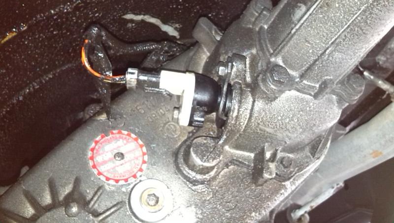
Speedo gear showed up today. To swap this guy out locate the speed sensor near the transfer case tail housing
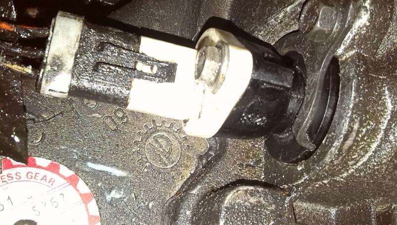
A close up shows the horseshoe style clip used to retain it
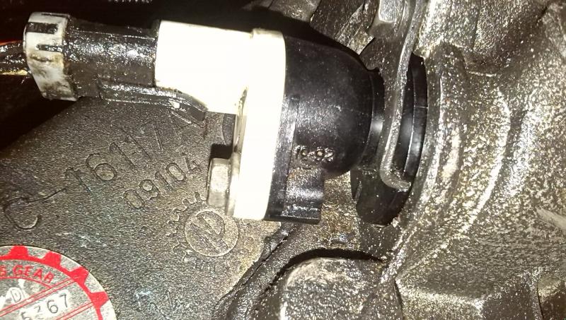
A 1/2" bolt holds it in place Note the marking "26-31" which is oriented in the 6 o'clock position (pointing down to the ground) used with a 30 tooth gear. After taking this horseshoe clip off the sensor assembly pops right out
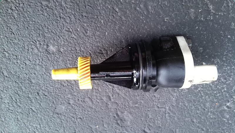
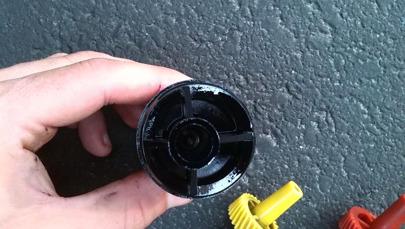
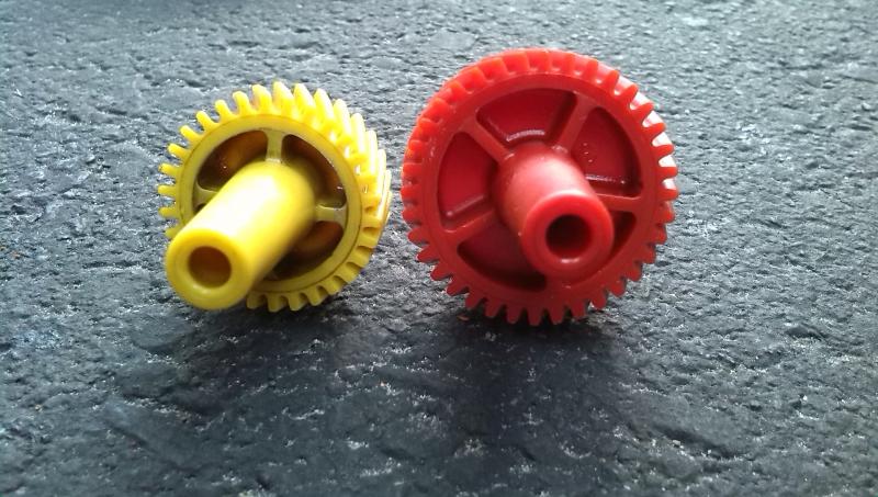
The speed sensor housing can fit in the transfer case in 4 different possible orientations depending on the amount of teeth the pinion gear contains. I'm assuming Chrysler uses this speed sensor for a large variety of vehicles as a wide range of pinion gears are covered. The adjustability is facilitated by the offset input shaft of the speed sensor where the pinion slips into, seen below
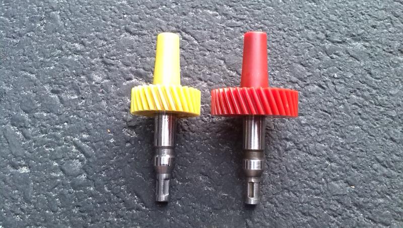
This is required because as you increase the amount of teeth on a gear and maintain the same diametral pitch (required in order to properly mesh with the original 13 tooth driven gear), your pitch diameter must increase and therefore you have a larger diameter gear. So, clocking the sensor housing one way or another pushes the pinion gear closer or further to the driven gear. Here is the old gear vs the new one
To swap the gear simply yank on the old one to pull it out and firmly press the new one in. Since I have a 36 tooth gear I had to clock the housing 90 degrees from where it came out. Here is a shot of the sensor back in with the "32-38" marking oriented in the 6 o'clock position. The range marking that corresponds to the # of pinion teeth you have must be oriented at 6 o'clock or your speedo will not work
My speedo is now dead on which is awesome. Won't be getting 1.2x the mileage anymore though
Last edited by oxymoron29; Aug 12, 2014 at 09:59 AM.
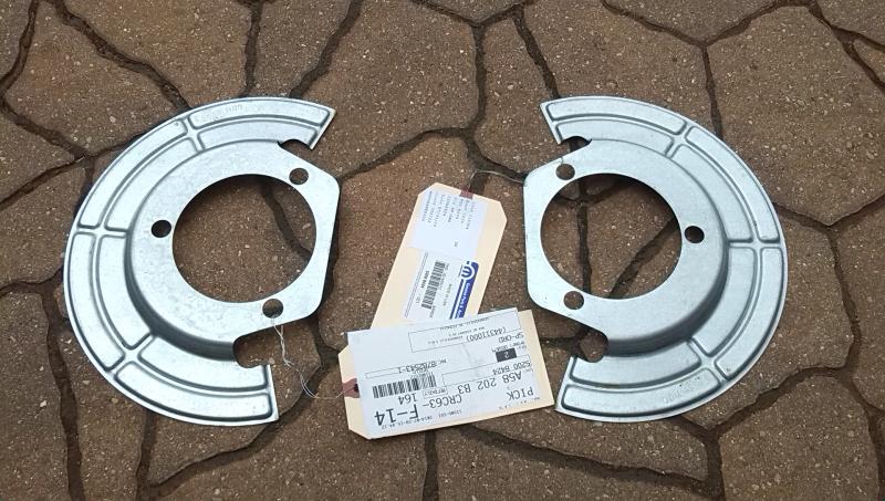
Ordered some brake dust shields awhile back and they finally showed up
The originals are getting pretty tired, specifically on the mounting flange. Figured that out when doing the ball joints last year so since I'll have it all apart again I figured why not. These things were pretty hard to find and not cheap for pieces of galvanized tin. For anyone interested they are part number 52008424 sold individually (both sides are the same). I got them through a newer site called MoparAmerica.com which I was a bit skeptical of at first however they came through and had the best price.
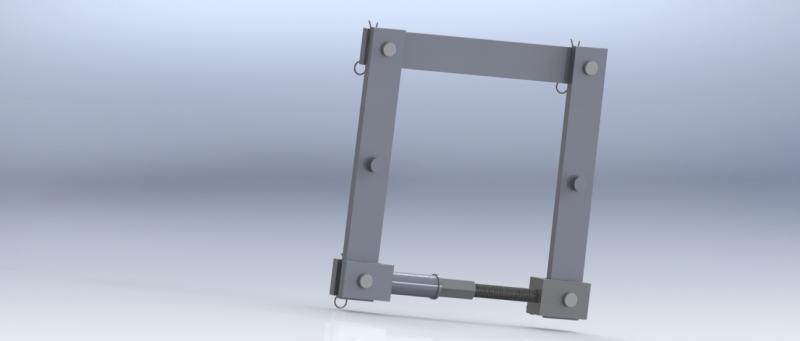
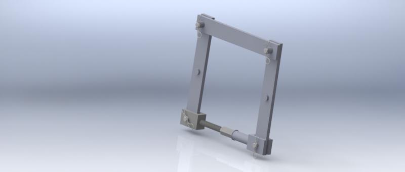
I also did some measurements and made a quick CAD model of the diff spreader design I had in mind for the front
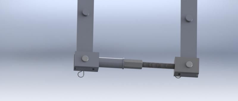
It's all made of 1/2" x 2" flat bar which should be sufficient if not a bit overkill. Dowel pins for the spreader holes are 0.875". I used clevis' to attach the 4 corners but I will likely just use hitch pins as I have 4 5/8" ones already. The threaded rod will be welded to the clevis on one side and a 3/4" ID tube on the other to accept it. Might make the clevis longer on the threaded rod size to reduce the length of the rod. I'll use a washer for load distribution / less friction and a coupling nut to distribute the load over a greater number of threads. Some anti-seize lube on the nut / threaded rod should be just fine to assist moving it. Now just have to finalize the dimensions, get some big drill bits, materials and find some time...
Last edited by oxymoron29; Aug 25, 2015 at 02:19 AM.
Good concept. I know that version is out there, but I'd suggest (since you are building it) you have 2 threaded rods. Moreover, make sure they are fine thread. No need to make them that long as you show in the picture. Reduce the stroke, therefore you reduce flexibility in the system. That is important in the realm of mils. Maximum diff opening is 0.015" iirc, as in absolute. 2 threaded rods will give you more certain displacement measurement rather than factor in the angle. Another suggestion is incorporating a stick on ruler. Similar to what table tops saws have.
Nice work and I like the idea of using the hitch pins. Cost effective.
Stopped off at the metal store on the way home and found some suitable off cuts for $15. Should be enough to do the whole deal and then some. Also grabbed a 3/4" coupling nut
Wh1t3, My aim was to replicate the Chrysler tool W129B which uses a single adjustable end, however I had seen designs with 2-side adjustability also. I didn't see a need for it as any angle in the system (so long as I have my measurements right) is pretty much negligible. Max spread is 0.020" (0.5mm) and I'll be using my dial indicator to measure so that shouldn't be an issue.
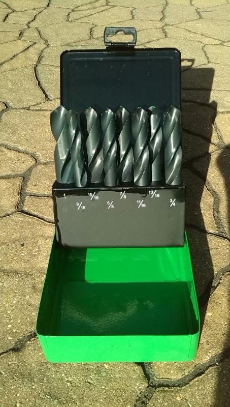
Also got my big honker drill bit set today, couldn't pass it up at $35 for a set of 8
Wh1t3, My aim was to replicate the Chrysler tool W129B which uses a single adjustable end, however I had seen designs with 2-side adjustability also. I didn't see a need for it as any angle in the system (so long as I have my measurements right) is pretty much negligible. Max spread is 0.020" (0.5mm) and I'll be using my dial indicator to measure so that shouldn't be an issue.
There is no arguement for going as cheap as possible. That is the common thing to do and presume it will meet or exceed the tool to replicate. In some cases it's very plausible. This is not one of them. My suggestions were only to ensure even tighter control for the operation. The design you show lacks that control, but it will still do the job.
The design you say that is being replicated is not what you show. At least not in this link -- I'm sure other variations. Take note the length of the adjuster piece and how it is captured, which is purposeful. Hence my comment to make it short, among other things.
The design you say that is being replicated is not what you show. At least not in this link -- I'm sure other variations. Take note the length of the adjuster piece and how it is captured, which is purposeful. Hence my comment to make it short, among other things.
You are correct and I will be addressing the clevis length to minimize threaded rod length when I get a moment to change it up (later today hopefully). You're also right in saying I havn't exactly replicated the Miller tool. I moreso made a hybrid of one I had seen on eBay for the adjustable portion and used the main frame design of the Miller one.
Speaking of which, my model has the upper link in single shear; I will be changing that to double shear. I was under the impression from pictures in the manual that it was in single, which I thought was odd but rolled with it anyway. I'll throw up an updated model with these changes.
Originally Posted by Wh1t3NuKle
Where do you find max spread of 0.02" for the Dana 44? Page 48 states 0.015" as I recalled. Good to know other sources of info out there.
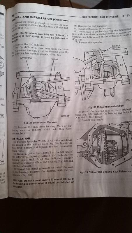
Wow, that's a bit ambiguous. Page 48, like you say, says 0.015" however page 36 states 0.020". Initially I got the 0.020" from my '97 FSM:
Also note how different the spreader in the FSM looks than the one you linked. Usually FSM pics are pretty detailed so I based my design moreso on this. Perhaps Chrysler found this to be a bad design and changed it up?
So something about new job, busy life, blah blah blah...I went last winter without the use of 4x4 and it wasn't fun. Finally got around to prepping all the tools to do the Dana 44 and finished this past weekend. Took all day Saturday, Sunday and half of today to do. I'll update with the process as time allows.
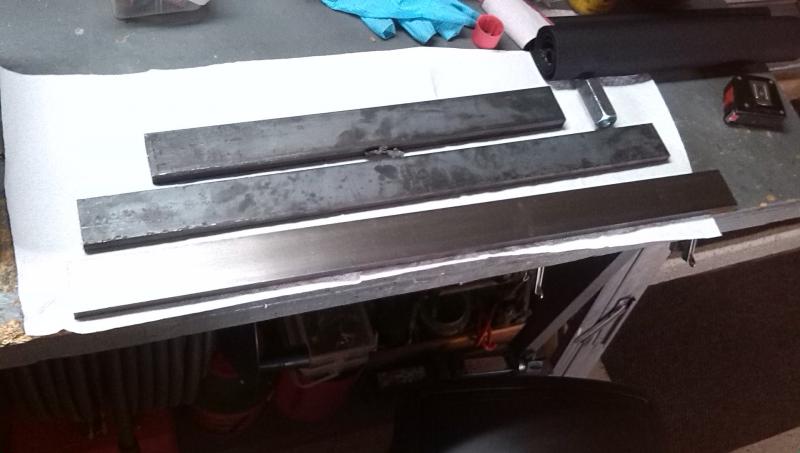
Didn't ever end up updating the CAD model of my spreader so I just made it with what I had in mind
Traded some work for some seat time with a mill to drill these suckers. Vertical members are on the left and right
Welded up the horizontal members with double shear ends
I used .035 flux core with my cheapo 220v welder with heavy bevels on all edges and it turned out great
Welded in short dowels where the spreader attaches to the case. Tacked these only as I wanted the ability to remove them in future should I need the spreader for another diff with different sized dowels
Bought some hardware and mocked it up
Cut to size and welded on the business end. I used 3/4" tube, 1/8" wall with 3/4"-16 threaded rod and a coupling nut to match. I had to go to the ends of the earth to find the rod locally. OK not quite but major metal stores did not carry it
I put a grade 8 washer between the nut and the tube and a healthy amount of anti-seize on the threads to lighten the load
WHERE is the "Like" button? And the, "add to user's reputation" button?!
This OUGHTA be a sticky! I redid my axles with Nitro gears 2 1/2 years ago, but you're right - the D44 has lots of writeups, but NOT the 9 1/4".
I had the best 4x4 shop in Pittsburgh do mine - no complaints - as we both have the 318 Magnum with factory 3.55 gears (presumably an A518 as well). I knew with the hills, stop signs every 5' around here, & 35's, that factory setup was gonna be a losing combo right away!
The 9 1/4" axle is a decent axle, if you're gonna run 35's or smaller, and you can go as deep as 4.88's if need be (I almost did!). Nice job, writeup, and good pics, too!
My initial plan last year was to re-use the factory bearings as I figured they'd be immaculate since none of the bearings are turning unless the truck is in 4x4. Well that plan got scrapped as I read further into the FSM and realized the setup procedure. I ended up ordering locally a "master" bearing kit with Koyo's
I say "master" as it came with no shims, cover gasket, pinion nut, marking paint or ring gear bolts. Good thing my Ratech kit did. A word on Ratech's stuff, their 122K minor kit that is supposedly for a 94-02 Dodge front end is in fact incorrect. The Dodge D44's have a crush sleeve whereas my minor kit came with 4 different shim packs for use with a solid spacer, which was not included. I will be giving them a call to hopefully get some compensation as both their website and Summit have misadvertised the kit.
In addition to the master kit, I picked up another pair of carrier bearings to make setup bearings out of as these would need to come off multiple times, and much like the rear I figured I'd have to cut the originals off
The work area
Disassembly
CAD shift motor
Inside the CAD housing. Right axle shaft removed, intermediate shaft in place with shift collar
Shift collar
Intermediate shaft with collar removed
Pain in the *** axle seal to the right of the CAD housing
You must yank the intermediate shaft over to the right side to disengage the splines from the carrier
Yanked the cover, original gear set was in good shape
Time to pull the carrier out using the spreader
I had to fab up a little piece of angle iron with standoffs to mount my dial indicator on as it was a little short. You must set this up each time you take out or put in the carrier and spread the case no more than 0.020". I played it safe and stayed at 0.015" spread each time.
Max spread. Check out how the verticals bowed. This is 1/2" x 2" bar by the way. It takes a TREMENDOUS amount of force to spread this thing.
I've read people saying that they have done this job without a spreader, and I really can't see how. I had to pry the carrier out pretty good even with it spread. There is a LOT of preload from the case on the carrier bearings. You would need to do some serious prying and sledge hammering to get it out and back in without a spreader.
I ran a quick pattern on the 3.55's before taking them out just out of curiosity, looked pretty good
Carrier out
Ring gear off
Old vs. new
This is where things get fun (stupid) again. If you'll remember I stripped out my rear end bolts over-torquing due to my torque wrench not functioning for left hand threads. On the D44 they are regular right hand.
The FSM calls for 80 ft lbs for these 3/8" ring gear bolts. Fine. Installed the new ring gear on, tightened all the bolts, then went to torque them to 80. Guess what? Stripped it. After nearly throwing the wrench across the garage I took it out
Checked the ring gear threads and they were OK. These bolts supplied by Ratech had grade 8 markings on them but I thought they had to be made out of cheese. Took them all out and to my surprise many of them were at the onset of stripping. Son of a bitch. Has to be ****ty bolts.
Back to the original bolts. Got them all in, tightened and ready to torque up. I decided to go in steps this time, 40 ft lbs first, then the final 80. Stripped first bolt I tried again. This is the original grade NINE (9) hardware I'm using and I couldn't even reach half the torque the manual is calling for. Cuss, swear, throw tools, etc.
I started placing blame on the torque wrench, so I used my other one and tried another bolt. Stripped again. Tried both wrenches on my lug nuts and confirmed they were working properly. I ended up going out and buying a new set of grade 8's at the local bolt supply and trying this whole thing again, at a lower torque. There was no way in hell I was going anywhere near even half of what the FSM was calling for.
New bolts
Before torquing I checked charts for standard torque ratings of grade 8 bolts. Turns out a 3/8" fine thread grade 8 bolt is only rated at about 44 ft lbs dry and 37 ft lbs lubricated. I have no idea where Chrysler is getting there numbers from but I can confirm 80 ft lbs is totally NOT the correct value. I had been lubricating the bolts with gear oil before putting in, so I did not want to venture even close to the rated value.
Long story short, through empirical testing the bolts were being WAY overtorqued even though I came nowhere close to 80 ft lbs. I torqued them all to 30 ft lbs and that is how they are staying.
Nice write-up for a first time gear installer. First thing I'll point out for you is that there is a specific type of bearing puller made to pull pinion bearings and differential bearings.
Here it is shown on Ebay but I am sure you can find it for sale from other vendors.
http://www.ebay.com/itm/Yukon-Carrier-Bearing-Puller-Dana-GM-Chrysler-Tool-/130455985393?hash=item1e5fc85cf1&vxp=mtr
Next thing to know is that some install kits come with a spacer and shims to replace the crush sleeve as a lot of people would rather get rid of the crush sleeve when possible. I know when I am doing gears on a rig if I have the choice I'd switch to shims over a crush sleeve any day.
Good job and I am sure you feel better by doing it yourself. Now as a long time mechanic I can tell you we are not all out to just screw the customer. Many of us would rather do a good job and want to have that customer come back again plus talk well of us to their friends so we might gain new customers. Not all mechanics are bad and not every shop is bad. Just because you had a bad experience with one doesn't make us all that way.