


Installing 2 digital gauges: 2 questions (pics)

Thread Starter
|
Champion
Joined: Jun 2004
Posts: 2,811
Likes: 2
From: Ft Campbell, KY/TN
Alright,
I am finally putting in my digal gauges (tranny temp and AFR). I have a couple of questions:
1. Since I am installing TWO gauges that need switched 12V power, how can I splice TWO fused connections and still be safe?
The reason why I ask, is because i don't want to splice two gauges to the ignition wire and then have problems because of current draw from one wire.
2. I also want to splice into the Dimmer switch. For when you can control how bright the gauges are. Or maybe should I just splice into the Headlight 12V power (on/off). I was just thinking that having the aftermarket gauges' backlight (illumination) be able to dim and brighten like the dash would be a nice addition.
3. How do I use a voltmeter on these wires? I don't know where to find a good ground around a bunch of plastic.
Here are some pics:
Which one is the dash illumination dimmer?
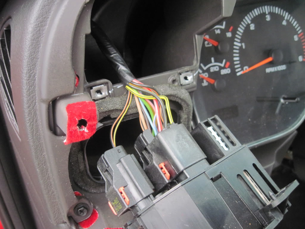
When I am testing these to see which one is a switched 12V, where yould you ground?
I am finally putting in my digal gauges (tranny temp and AFR). I have a couple of questions:
1. Since I am installing TWO gauges that need switched 12V power, how can I splice TWO fused connections and still be safe?
The reason why I ask, is because i don't want to splice two gauges to the ignition wire and then have problems because of current draw from one wire.
2. I also want to splice into the Dimmer switch. For when you can control how bright the gauges are. Or maybe should I just splice into the Headlight 12V power (on/off). I was just thinking that having the aftermarket gauges' backlight (illumination) be able to dim and brighten like the dash would be a nice addition.
3. How do I use a voltmeter on these wires? I don't know where to find a good ground around a bunch of plastic.
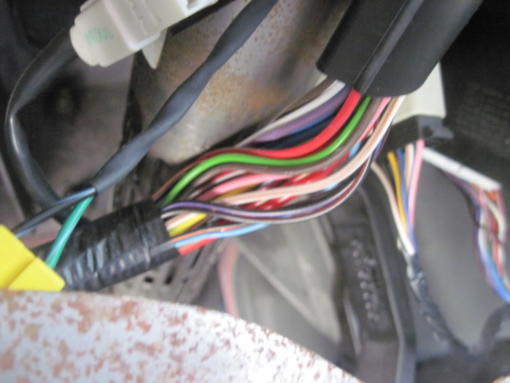
Here are some pics:
Which one is the dash illumination dimmer?
When I am testing these to see which one is a switched 12V, where yould you ground?
Administrator


Joined: Apr 2010
Posts: 87,468
Likes: 4,220
From: Clayton MI
There is a service manual in the FAQ section, that has wiring diagrams (including wire colors  ) for your truck. You should be able to look at the diagrams, and pick the wire you want easily, without ever having to disassemble the truck. (which you already have..... ah well.)
As for ground, use a door hinge, or something else metal for the VOM. If you are referring to grounding the gauges...... have a very close look at the wiring diagrams... dodge seems to like have circuits always powered, with switches and such providing the ground....... Make sure you don't provide a ground for a circuit, that is unswitched, hence, leaving them ON all the time......
) for your truck. You should be able to look at the diagrams, and pick the wire you want easily, without ever having to disassemble the truck. (which you already have..... ah well.)As for ground, use a door hinge, or something else metal for the VOM. If you are referring to grounding the gauges...... have a very close look at the wiring diagrams... dodge seems to like have circuits always powered, with switches and such providing the ground....... Make sure you don't provide a ground for a circuit, that is unswitched, hence, leaving them ON all the time......
Thread Starter
|
Champion
Joined: Jun 2004
Posts: 2,811
Likes: 2
From: Ft Campbell, KY/TN
There is a service manual in the FAQ section, that has wiring diagrams (including wire colors ) for your truck. You should be able to look at the diagrams, and pick the wire you want easily, without ever having to disassemble the truck. (which you already have..... ah well.)
As for ground, use a door hinge, or something else metal for the VOM. If you are referring to grounding the gauges...... have a very close look at the wiring diagrams... dodge seems to like have circuits always powered, with switches and such providing the ground....... Make sure you don't provide a ground for a circuit, that is unswitched, hence, leaving them ON all the time......
) for your truck. You should be able to look at the diagrams, and pick the wire you want easily, without ever having to disassemble the truck. (which you already have..... ah well.)As for ground, use a door hinge, or something else metal for the VOM. If you are referring to grounding the gauges...... have a very close look at the wiring diagrams... dodge seems to like have circuits always powered, with switches and such providing the ground....... Make sure you don't provide a ground for a circuit, that is unswitched, hence, leaving them ON all the time......

Veteran
Joined: Mar 2010
Posts: 328
Likes: 1
From: BC, canada
the black/yellow at the headlamp switch is the positive for the park lights..and the blue wire in the ignition harness is switched 12v positive..if your worried about draw..which i wouldnt be install some relay's..couldn't tell you on which wire is the dimmer switch thou.
Thread Starter
|
Champion
Joined: Jun 2004
Posts: 2,811
Likes: 2
From: Ft Campbell, KY/TN
Yeah, i got the black/yellow. ANd the blue.
I am installing some fuses in line with the gauges. 3 amps for each gauge.
Thanks for helping. Now that I hear you saying something I was thinking along the same lines of...I feel much better going forward.
--Dan
I am installing some fuses in line with the gauges. 3 amps for each gauge.
Thanks for helping. Now that I hear you saying something I was thinking along the same lines of...I feel much better going forward.
--Dan

Record Breaker
Joined: Nov 2005
Posts: 1,827
Likes: 3
From: Ontario Canada
Not positive if Im reading the schematics correct but think that the dimmer pwr lead is the pink with light blue tracer.
Check 01service manual
Go to page 8W-50-2 (also see it 8W-45-7)
Bottom left of the Central Timer Module C2 on left side is the Courtesy Lamp switch output
Goes to courtesy lights & cluster from there.
Check 01service manual
Go to page 8W-50-2 (also see it 8W-45-7)
Bottom left of the Central Timer Module C2 on left side is the Courtesy Lamp switch output
Goes to courtesy lights & cluster from there.
Trending Topics
Thread Starter
|
Champion
Joined: Jun 2004
Posts: 2,811
Likes: 2
From: Ft Campbell, KY/TN
Not positive if Im reading the schematics correct but think that the dimmer pwr lead is the pink with light blue tracer.
Check 01service manual
Go to page 8W-50-2 (also see it 8W-45-7)
Bottom left of the Central Timer Module C2 on left side is the Courtesy Lamp switch output
Goes to courtesy lights & cluster from there.
Check 01service manual
Go to page 8W-50-2 (also see it 8W-45-7)
Bottom left of the Central Timer Module C2 on left side is the Courtesy Lamp switch output
Goes to courtesy lights & cluster from there.
NOW IS THE LAST QUESTION AND I CAN INSTALL:
For the 12V power from ignition:
1. I am going to fuse this, but can I install BOTH power leads (one from the tranny and one from the AFR gauge) to the same connection in the fuse?
It calls for a 3 amp fuse for each gauge, so does that mean I need to use 6 amp for this?
I was thinking this:
__________12V ignition_________
|
|
splice
|
/\
/ \
3A 3A
| |
Tranny temp AFR gauge
OR:
__________12V ignition_________
|
|
3A
|
/\
/ \
| |
Tranny temp AFR gauge
Thread Starter
|
Champion
Joined: Jun 2004
Posts: 2,811
Likes: 2
From: Ft Campbell, KY/TN
OK it did not come out like I spaced it but you can catch my drift. It is either a bare splice that splits to 2 3A fuses (one for each gauge). OR splicing a 3A fuse and then splicing the AFR and tranny temp gauges to the 3A fuse.
OR, for the second one would I need a 3 Amp fuse.
I don't know if you add the amps together or not.
OR, for the second one would I need a 3 Amp fuse.
I don't know if you add the amps together or not.
Thread Starter
|
Champion
Joined: Jun 2004
Posts: 2,811
Likes: 2
From: Ft Campbell, KY/TN
OK,
Everything is wired. The tranny temp gauge works great. The AFR gauge needs some more work (shop to weld the bung on for the O2 sensor).
Everything seems fine. I used some beefier splicers and that worked well. They are the "all weather" ones from autozone. They came covered in dielectric grease and the plastic was harder.
Well, this was not as hard as I thought. it was just a lot of work to prepare for (since I never did this before except for an analog water temp sensor).
I will take some pics later tonight. I have to eat dinner.
--Dan