P0132/P0138, Intermittent Rough Idle
#11
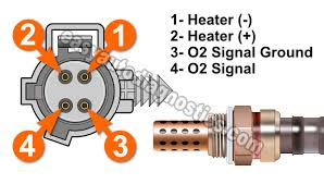
Agree with your reasoning that the 02 heaters could be the problem. The heaters get power via the ASD on the dark green/white wire and the PCM activates them by grounding the brown/white or brown/violet wire (color depends on sensor location). You have 12 V on dg/wt, and when the PCM activates the heater there should be no voltage differential between sensor control and ground. So not sure what to think of the 2V you measured. Could be a PCM grounding issue or wiring.
The PCM doesn't really monitor the heater circuit, it just sees that the sensor signal isn't working some time after the heaters are turned on and concludes there's a problem with the heater. I'd disconnect the sensors and see if the heater circuits correctly switch a load like a light bulb.
The PCM doesn't really monitor the heater circuit, it just sees that the sensor signal isn't working some time after the heaters are turned on and concludes there's a problem with the heater. I'd disconnect the sensors and see if the heater circuits correctly switch a load like a light bulb.
#12
#14
#15
PCM expects voltage from the heater wire, or the heater control wire? Also, I'm just now realizing by looking at this wiring diagram that it appears the rear o2 sensor is not heated, because the only wires it has are power, ground, signal, and signal control.
#16
If I remember correctly, heater circuit is powered via the ASD relay, which has to be working, or the truck wouldn't run.  (It also provides power to the coil, and injectors.....) Since you are getting 12 volts IN, but only 2 volts out..... I suspect THAT is the problem. So, either a bad connection at the sensor connector, or, a failed sensor.
 (It also provides power to the coil, and injectors.....) Since you are getting 12 volts IN, but only 2 volts out..... I suspect THAT is the problem. So, either a bad connection at the sensor connector, or, a failed sensor.
#17
If I remember correctly, heater circuit is powered via the ASD relay, which has to be working, or the truck wouldn't run.  (It also provides power to the coil, and injectors.....) Since you are getting 12 volts IN, but only 2 volts out..... I suspect THAT is the problem. So, either a bad connection at the sensor connector, or, a failed sensor.
 (It also provides power to the coil, and injectors.....) Since you are getting 12 volts IN, but only 2 volts out..... I suspect THAT is the problem. So, either a bad connection at the sensor connector, or, a failed sensor.
Also, I'm not sure it's actually 2 volts OUT per say. The testing was done with the sensors not plugged into the harness (I don't have the skinny leads to test pin connectors while they're still pinned, I'd have to strip some off the cable to test). It's 2 volts hanging around in that 1 wire while unplugged from the sensor. Meaning the 2v is coming FROM the PCM on the Tan/White wire....right?
Last edited by Skeptic68W; 06-20-2020 at 11:12 PM.
#18
#19
#20
As I wrote before, and AFAIK the PCM has no means of checking the heater circuit directly. Nowadays electronic control modules can figure out if something is disconnected or a lamp is burned out but these PCMs are a 20+ year old design. P0135 code criteria is "The control module monitors how long it takes the sensor to warm up and start sending an adequate signal. The code is triggered when the sensor is taking too long to warm up."


