


Passenger windows will not go down...


Veteran
Joined: Feb 2010
Posts: 423
Likes: 0
From: Houston, TX
There's a great write-up in the FAQ section by Denniss66. He mentioned a different fix rather than soldering, but there are a lot of good pictures showing the dissassembly.
https://dodgeforum.com/forum/3rd-gen...-lock-diy.html
https://dodgeforum.com/forum/3rd-gen...-lock-diy.html
Rookie
Joined: Oct 2008
Posts: 67
Likes: 0
There's a great write-up in the FAQ section by Denniss66. He mentioned a different fix rather than soldering, but there are a lot of good pictures showing the dissassembly.
https://dodgeforum.com/forum/3rd-gen...-lock-diy.html
https://dodgeforum.com/forum/3rd-gen...-lock-diy.html
Veteran
Joined: Feb 2010
Posts: 423
Likes: 0
From: Houston, TX
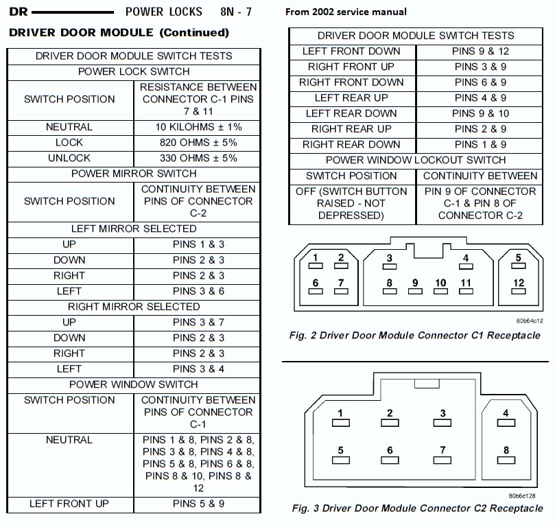
Alright, I just went thru the service manual for my 02 and I did a little cut and copy so this would be a nice consolidate pic showing the pin outs and connectors for the Driver Door Module. I'm not sure how many years they used this same connector but I doubt it's changed much since so many of us have the same problem.
It looks like C2 is mostly for the power mirrors and C1 has most of the window circuits, however the point of failure is with the lockout switch and to test that you have to test the continuity between both connectors. I'm going to try this again.

It looks like C2 is mostly for the power mirrors and C1 has most of the window circuits, however the point of failure is with the lockout switch and to test that you have to test the continuity between both connectors. I'm going to try this again.
Champion
Joined: Aug 2007
Posts: 4,702
Likes: 2
From: N. Florida
The switch could easily show continuity even if it isn't "communicating" with the passenger windows. The problem is that when the solder connections fail, the switch is no longer connected to the circuit board. The two poles of the switch will still show the proper condition regardless of whether the solder connections are good or bad (unless the switch is bad, and no one has mentioned that occurrence).
The solder connections are there even on a regular cab truck (which has no lock-out switch, apparently).
The solder connections are there even on a regular cab truck (which has no lock-out switch, apparently).
Rookie
Joined: Oct 2008
Posts: 67
Likes: 0
So just to clarify, with the switch up (off position...passenger switches enabled), your meter would show continuity between connector 1, pin 9, and connector 2, pin 8. If the solder (or trace) is broken, then your meter would show "open" between these two pins...same as if the switch was down (on position...passenger switches disabled).
Veteran
Joined: Feb 2010
Posts: 423
Likes: 0
From: Houston, TX
What? If the switch itself is defective / open, then how would there still be continuity between the circuit connectors on the bottom of the switch panel. The wiring diagram stated that when there is continuity, then the switch itself is in the 'closed position' which should allow the windows to work from all switches. If the solder breaks in the switch then it would always be 'electrically open' and no continuity and no window controls.
I was going to use my multimeter yesterday after i posted that but when I opened the garage Fedex showed up with my radiator.
I was going to use my multimeter yesterday after i posted that but when I opened the garage Fedex showed up with my radiator.
Champion
Joined: Aug 2007
Posts: 4,702
Likes: 2
From: N. Florida
Yes, if the switch itself is bad, then it would likely fail open. However, failure of the switch is very unlikely, and of all the posts on the forums I've read, no one has found a bad switch. The problem was either broken solder joints or broken wiring. The majority was broken solder connections. There is no switch connection going out to the wiring harness, it's all contained in the circuit board.
Yes, switch button up is circuit closed, switch button down is circuit open. You'll have to get right down against the board to find the open due to bad solder connections and it will be open regardless of the switch position. Out at the tip of the pins (the actual switch connection), it will read a short with the switch up (closed) and an open with the switch down (open). The switch itself is either a dead short or an open. There won't be any "load" (resistance above 0, but less than infinity).
The solder connection fails between the tip of the switch pin and the circuit board. The cracks in the solder connection on mine were tiny, which would explain how it could work for a few days/weeks and then fail again. The odds of a failure of the cable harness to the circuit board are pretty slim: there is little to no stress on the connector and it has a pretty good grip on the module.

