


Adding LED Strips

Thread Starter
|
Veteran
Joined: Sep 2012
Posts: 362
Likes: 0
From: Colorado Springs, CO
Cool, now I can read a welding blueprint all day, I know a little but the schematic you drew up has me a little confused. I honestly don't know which wires to connect to the relay from your drawing and what some of the symbols stand for. I know what the ground symbol is but besides that I'm a little lost. You may have to break it down barney style lol.

Champion
Joined: Aug 2006
Posts: 4,489
Likes: 4
From: New Jersey
Champion
Joined: Aug 2006
Posts: 4,489
Likes: 4
From: New Jersey
where are you pulling 12V constant from?
The way I have it wired in the drawing I made for you it will drain a TINY bit like .01mA/hr and that is just b/c of it dead ending at the relay.
so it would take a long time to drain the battery.
The way I have it drawn the battery power will only come on through the switch and as long as the current draw is under 3A the switch will be fine, all we are using the dome light circuit for is to energize the relay and allow battery power to flow to the LEDs.
I mean we can beef the circuit up by adding another SPST relay that will operate only the dome light function and then the DPDT relay that will handle the button switching, but that will make things complicated and you'll need some diodes so you don't dead end two +12V supplies together without a ground.
B/c you want the dome light to cause the LEDs to go on PLUS a switch to turn them on whenever you want is what is complicating this a bit, b/c we have to keep the dome light circuit separate from the 12V+ circuit from the battery.
If you were in NJ (or close by) I'd just tell you to pick up a 12 pack and stop by on a weekend and we'd wire her up... But Colorado is a little out there... lol


Thread Starter
|
Veteran
Joined: Sep 2012
Posts: 362
Likes: 0
From: Colorado Springs, CO
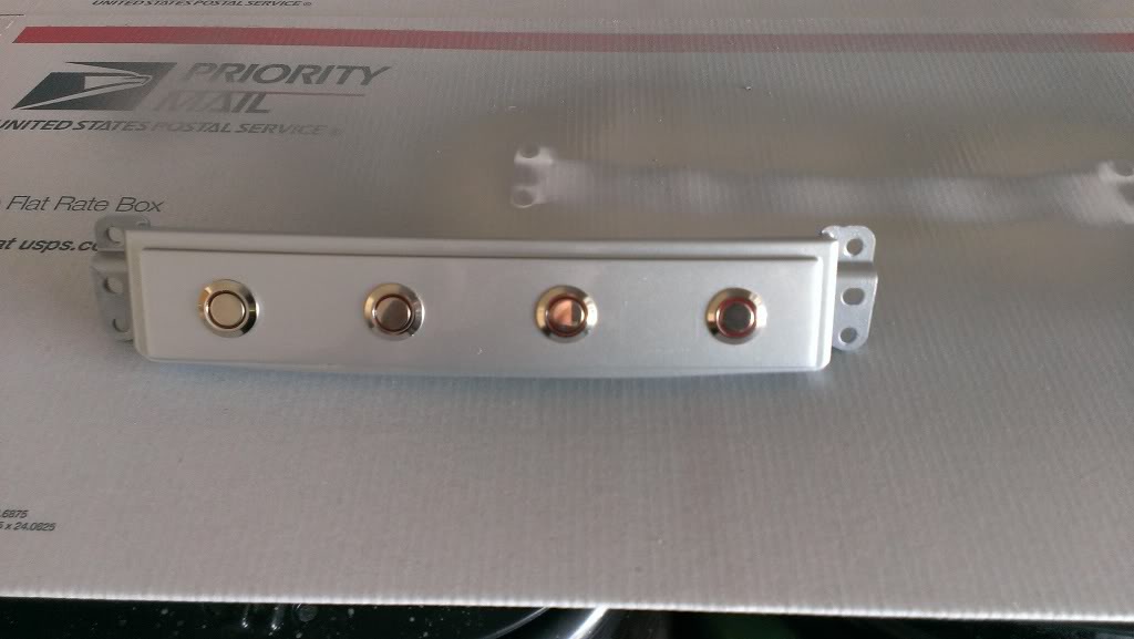
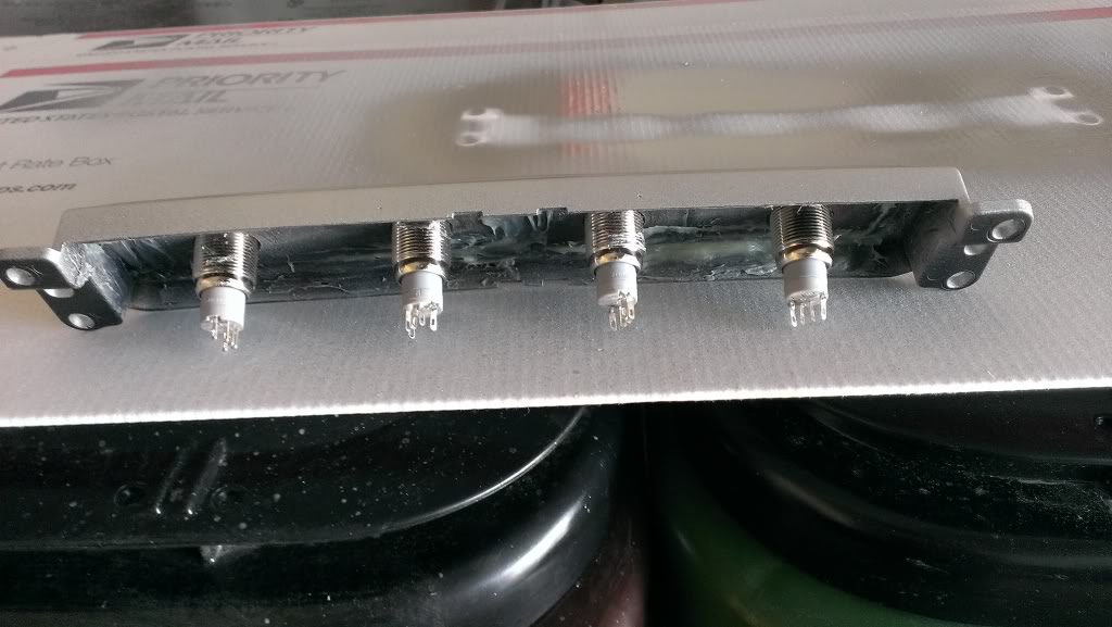
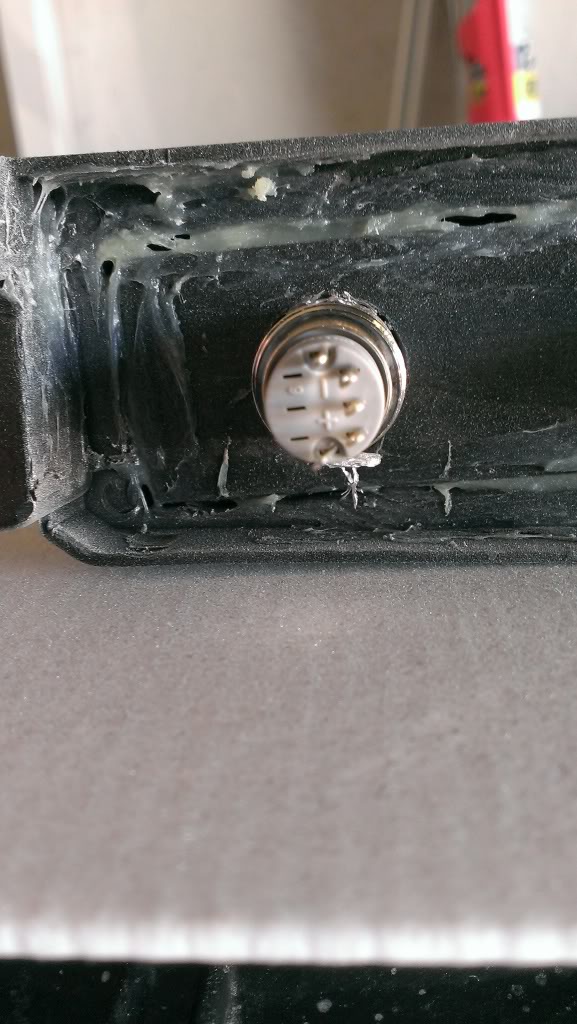
Step 1: I took an OEM heated switch bezel, gutted it, epoxied a plastic trip behind for strength and to help fill the holes, filled the 2 square holes with filler, drilled my holes, sand and painted. I have 3 on/off and 1 momentary for my e-cutout, and i also picked up some of the interior plastics to replace the ones i drilled previously for my hella's, e-fan, and e-cutout. I will add more info and some before and after pics when i wire it up, hopefully tom.


Thread Starter
|
Veteran
Joined: Sep 2012
Posts: 362
Likes: 0
From: Colorado Springs, CO
This advice was given to me from a guy on another forum, sounds to me like it will work.
I hope i give you the right info here, but i installed my own led strips in the footwells of the driver & pass side, as well as under the driver and pass seats so theres light in the back too. I wired it up exactly how you're describing for how you want it. I have them on a switch so i can turn them on and off whenever i want, and they also come on when I open up the door/unlock the doors. Its actually pretty simple, and only took me a couple hours, just because i hid every wire because i'm a bit of a perfectionist...but aren't we all when it comes to our trucks? Anyway, I had 4 seperate led strips. I tied the rear and front drivers side together, and same for the passenger side. Basically just + wire for back led's connected to + wire of the front LED's. Then do the same for negative. I used quick connects because they are easier than soldering to me. I did this for both sides. Then i bought some extra wire and ran a positive and negative wire from the rear dome light (i did this because it seemed easier to get to than the front dome light wiring). Then i just used quick connects and ran those wires to the positive and negative wire of the LED's. Since all 4 of my strips went to the same switch, i only had to do this for one side and it have power to all of the strips. So now its all wired up and will come on when the door is opened/unlocked. The only problem with doing it this way is if you turn the switch on to turn your LED's on, it will backfeed power to the dome lights and it will turn the dome lights on, which you dont want. Go to radioshack or whatever your electronic store is and buy a diode, i think mine was just 10 amp, even though you can get by with a 1 amp. If you dont know what it is, just ask, it looks like a tiny battery with a piece of wire coming out of each side. Solder this somewhere before your switch and this will keep the electricity from backfeeding from the switch to your dome lights. This is how i wired mine up and it works perfect! (sorry about the length, i know, tl;dr, but i just wanted to try to be clear!) Hope this helps!
I hope i give you the right info here, but i installed my own led strips in the footwells of the driver & pass side, as well as under the driver and pass seats so theres light in the back too. I wired it up exactly how you're describing for how you want it. I have them on a switch so i can turn them on and off whenever i want, and they also come on when I open up the door/unlock the doors. Its actually pretty simple, and only took me a couple hours, just because i hid every wire because i'm a bit of a perfectionist...but aren't we all when it comes to our trucks? Anyway, I had 4 seperate led strips. I tied the rear and front drivers side together, and same for the passenger side. Basically just + wire for back led's connected to + wire of the front LED's. Then do the same for negative. I used quick connects because they are easier than soldering to me. I did this for both sides. Then i bought some extra wire and ran a positive and negative wire from the rear dome light (i did this because it seemed easier to get to than the front dome light wiring). Then i just used quick connects and ran those wires to the positive and negative wire of the LED's. Since all 4 of my strips went to the same switch, i only had to do this for one side and it have power to all of the strips. So now its all wired up and will come on when the door is opened/unlocked. The only problem with doing it this way is if you turn the switch on to turn your LED's on, it will backfeed power to the dome lights and it will turn the dome lights on, which you dont want. Go to radioshack or whatever your electronic store is and buy a diode, i think mine was just 10 amp, even though you can get by with a 1 amp. If you dont know what it is, just ask, it looks like a tiny battery with a piece of wire coming out of each side. Solder this somewhere before your switch and this will keep the electricity from backfeeding from the switch to your dome lights. This is how i wired mine up and it works perfect! (sorry about the length, i know, tl;dr, but i just wanted to try to be clear!) Hope this helps!