

Tizzy1 and others DIY information


Rookie
Joined: Oct 2010
Posts: 85
Likes: 0
From: up upstate ny
Look on the bottom of the distribution cover and post what fuse relay is missing. Sound like you have multiple problems. Here is some info on fuses relays and how the sliding doors work. You will see lots of different things could go wrong with hatch and sliding doors.

try moving the sliding door fuse

How doors work


try moving the sliding door fuse
How doors work

Registered User
Joined: Jan 2011
Posts: 1
Likes: 0
Have a 2005 Grand Caravan SXT that I'm trying to replace the blower motor on. The housing seems to have a hidden fastener crammed up against the firewall-housing is loose and tilts down but won't come out. Any ideas?

SUBJECT:
Flash: 6 Speed Automatic Transmission Shift Improvements
OVERVIEW:
This bulletin involves selectively erasing and reprogramming the Powertrain Control
Module (PCM).
MODELS:
2008 (RT) Caravan/Town & Country (Includes International Models)
NOTE: This Bulletin applies to models equipped with a 3.8L/4.0L engine & 62TE
automatic transmission (Sales Code EGL/EGQ with DG2).
SYMPTOM/CONDITION:
Some customers may experience transmission shift or performance concerns as follows:
i. During a rapid coast down while braking a bump may be felt just before a stop
ii. 3 - 2 kickdown bump or harshness
iii. 2 - 3 upshift bump or harshness
iv. 4 - 3 - 4 change mind shift bump
v. Improved shift quality/driveability through all gear transactions
NUMBER: 21-017-08 REV. A
GROUP: Transmission
DATE: December 16, 2008
DIAGNOSIS:
Using a Scan Tool (StarSCAN�) with the appropriate Diagnostic Procedures available in
TechCONNECT, verify all engine systems are functioning as designed. If DTC's are
present record them on the repair order and repair as necessary before proceeding further
with this bulletin.
If the above symptom/condition is experienced or can be verified, perform the Repair
Procedure.
PARTS REQUIRED:
Qty. Part No. Description
1 04275086AB Label, Authorized Modification
SPECIAL TOOLS / EQUIPMENT REQUIRED:
NPN Battery Charger
CH9401 StarSCAN� Tool
CH9404D StarSCAN� Vehicle Cable
CH9409 StarSCAN� Documentation Kit
CH9410 StarSCAN� Ethernet Cable, 12 ft.
CH9412 StarSCAN� Software Update Device Kit
TechCONNECT PC or equivalent
REPAIR PROCEDURE - USING THE INTERNET TO RETRIEVE THE FLASH FILE:
NOTE: If this flash process is interrupted/aborted, the flash should be restarted.
1. Reprogram the PCM with the latest software. Follow the detailed service procedures
available in DealerCONNECT/TechCONNECT, Refer To Group 8 - Electrical >
Electronic Control Modules - Service Information > Module - Powertrain Control >
Standard Procedures > PCM/ECM Programming - Gas. After PCM reprogramming,
the following must be performed:
a. Clear the Variable Line Pressure (VLP) Counters, found in the StarSCAN� Misc
Function Menu. VLP Clear Counters must be completed on all models with a 62TE
transmission.
b. Clear any DTC's that may have been set in other modules due to reprogramming.
c. Perform the Quick Learn function, found in the StarSCAN� Misc Function Menu.
2. Type the necessary information on the “Authorized Modification Label” and attach it
near the VECI label.
OVERHEAD CONSOLE
REMOVAL
Open the transmitter bin door Overhead Console .
Remove screw holding the overhead console to the headliner. With the screw removed the console is retained by one engagement tab located inside the sunglasses storage bin.
Open the sunglasses bin door.
Press the retaining tab which is located directly under the door latch.
Lower rear of console away from headliner.
Pull console rearward to disengage clips holding front of console to roof armature and lower console.
Disconnect wire connectors from back of CMTC and reading lamps. Ensure the connectors lock tabs are fully depressed before disconnecting.
Remove overhead console.
INSTALLATION
Reverse the preceding operation.
I have a part number for the jumper harness for the 1996 1/2 minivans to the 1998 TRS sensors. This way you don't need to cut and spline the new connector. 5093968AA,This is a mopar number.
Veteran
Joined: Feb 2010
Posts: 309
Likes: 3
From: va
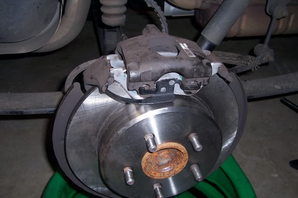
Thanks to help from Tizzy1 and this forum I have done rear disk brake pads and rotors on my 2006 Dodge Grand Caravan,
here is some pics and my advice, so use according to your own ability and at your own risk
warning, so brake materials might contain asbestos so you may want to use gloves, mask and eye protection for safety
it took me 45mins for the first side(taking pics)
2nd side took 25mins
then 20mins bleeding brakes
things you will Need
7mm Allen wrench socket
brake cleaner (I used 1 1/2 cans)
rotors,
pads
3/8 box wrench for bleeding the brakes
Dot 3 brake fluid
optional but I used,
caliper grease
and anti squeal grease
step 1
park the van on level surface, block the both sides of the front tires to prevent rolling
Loosen the Lug nuts
Make sure the Parking brake is Off
step 2
Jack up the back tire, (I only did one at a time) place it on jack stands
remove the tire
step 3
remove the two 7mm Allen head bolts
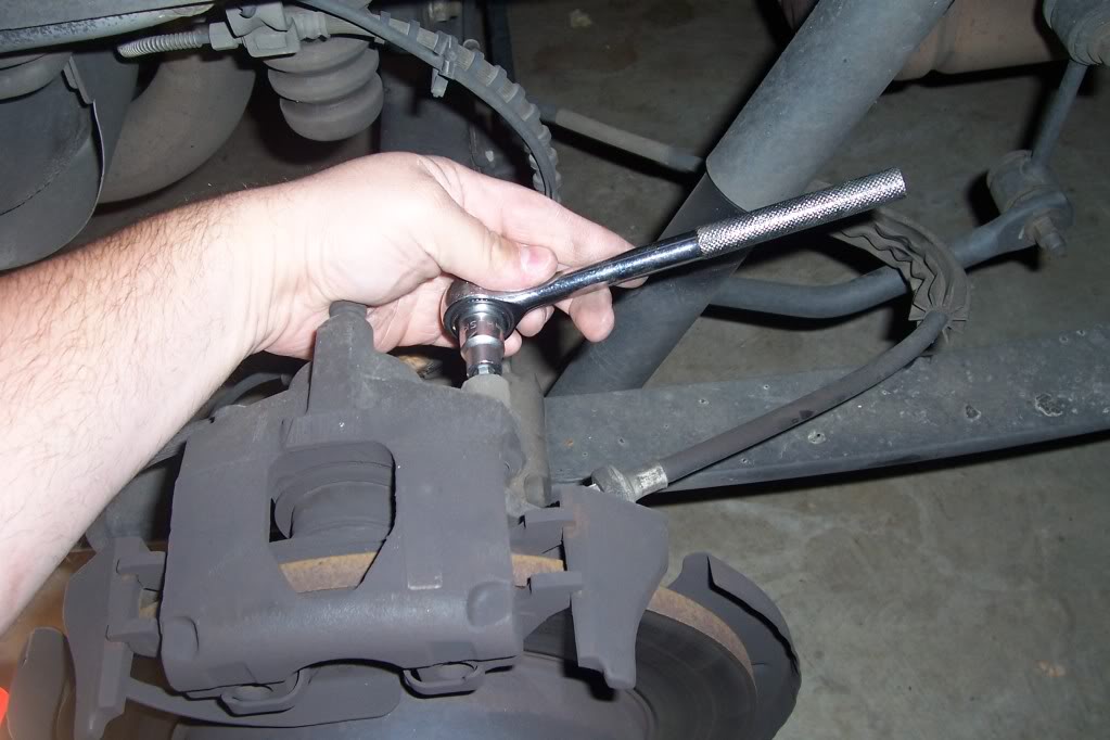
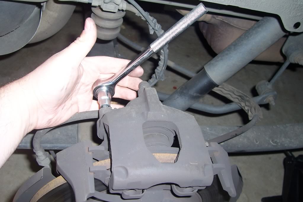
step 4
press the one side of the caliper up (press on the side opposite the metal spring type tab) takes a little force to get it loose, then it comes up freely
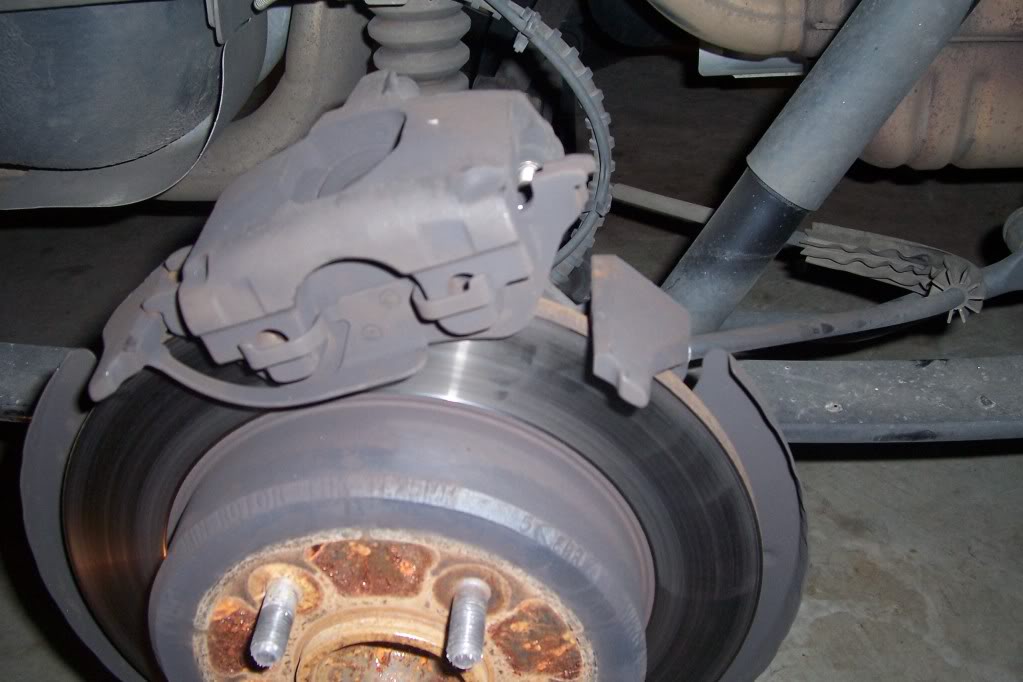
step 5
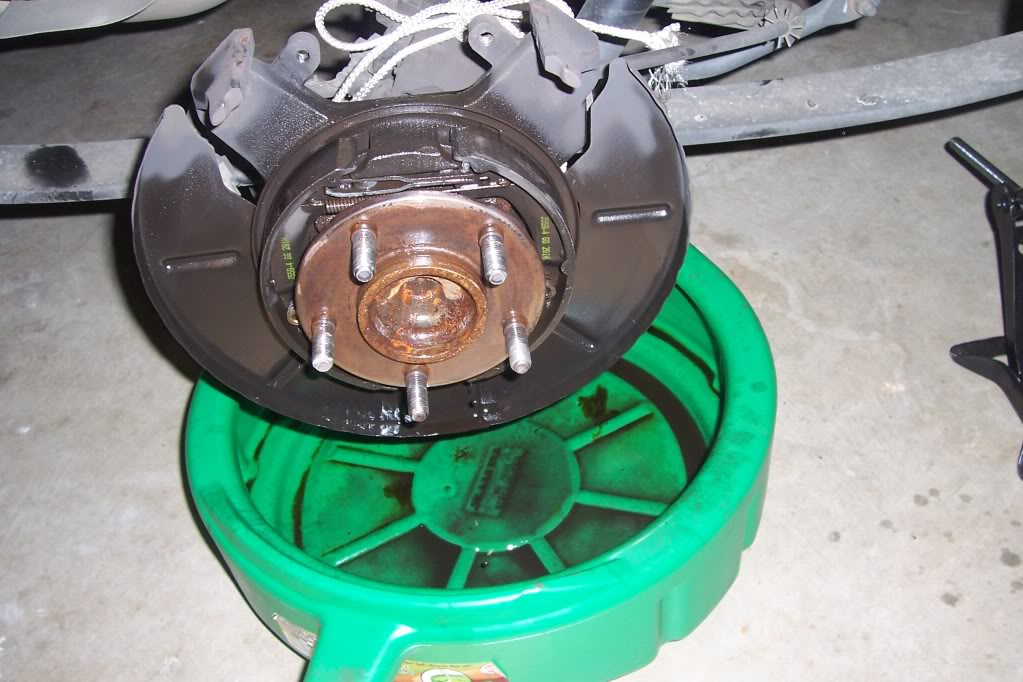
secure the caliper so that it is not hanging on the brake hose
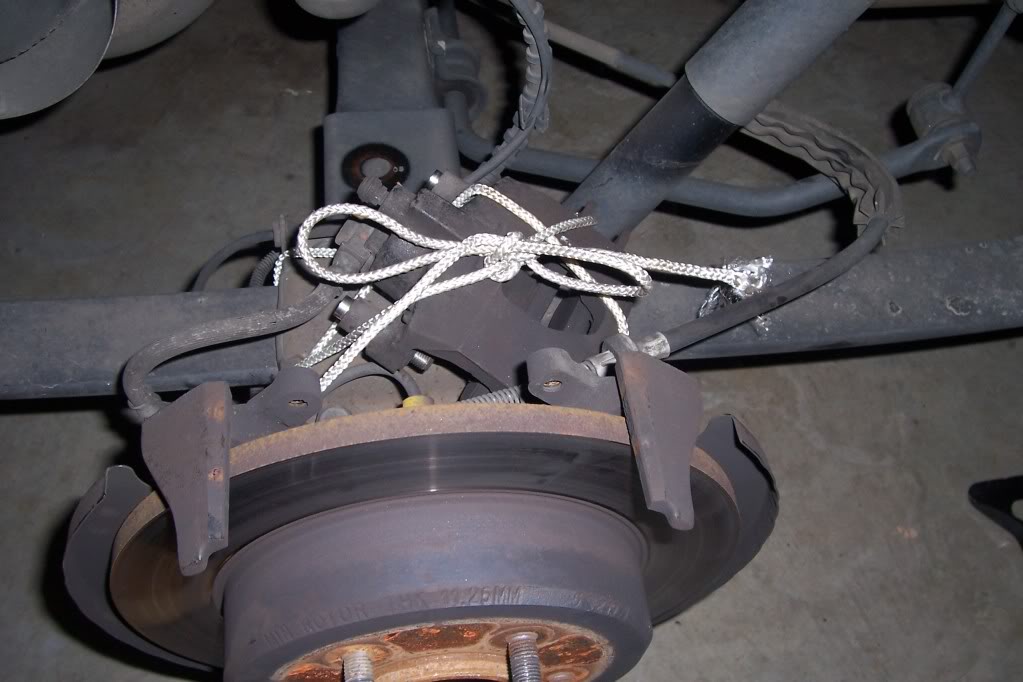
step 6
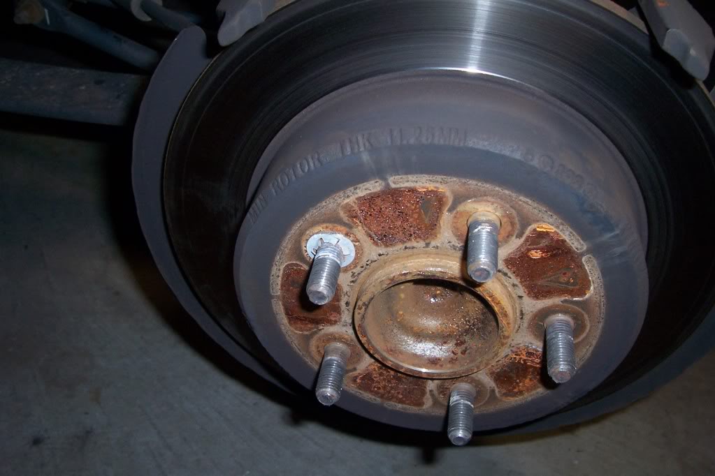
remove the rotors
they should pull right off, my first one came off easily
but the other side had never been removed, it still had a clip to hold the rotor on, simply remove it and discard it, that rotor I had to work to get off due to rust, I used a rubber mallet and whacked it along the center hub and on the back of the rotor being carefully not to hit anything else
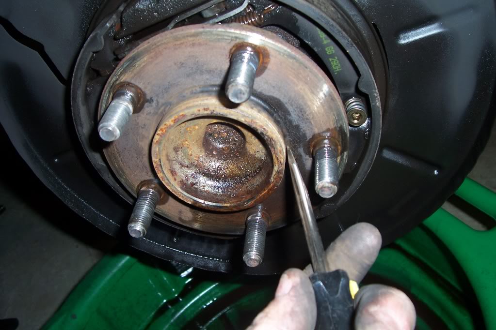
step 7
then I sprayed everything off with brake cleaner, being careful not to hit the rubber brake line
also when cleaning after that rotor came off I notice a slight build up off rust along the center hub, so I gently scrapped it off
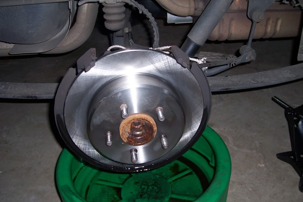
step 8
take the new rotor and spray it off with brake cleaner to get the packing oil off,
then simply slide it on to the wheel studs
step 9
press down on the outboard side of the brake pad (it takes some pressure to get it to separate, then simply pull the pad off
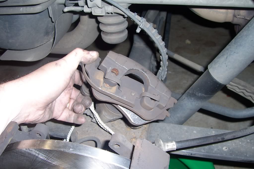
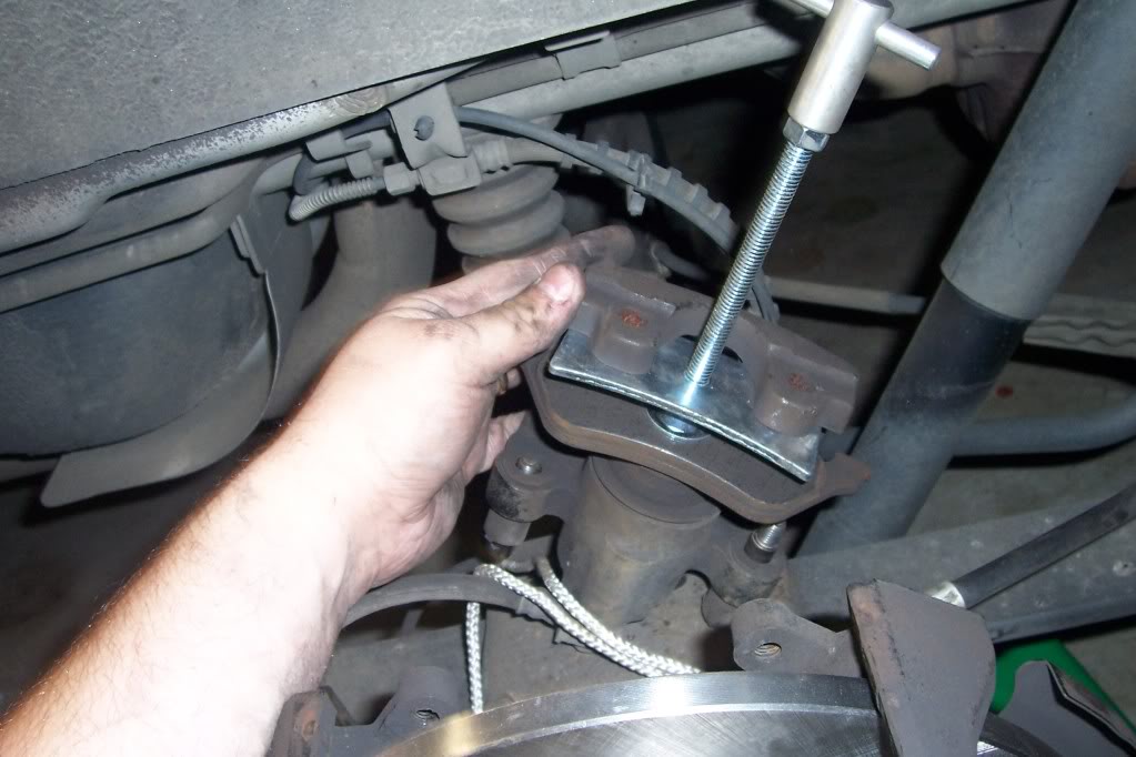
step 10
using the brake caliper compression tool on top of the old inboard brake pad, Slowly compress the brake caliper, you will want to keep an eye on the master cylinder to make sure it does not over flow, you may have to remove some fluid so it does not over flow
( I personally opened the brake bleeder valve just a crack to help)
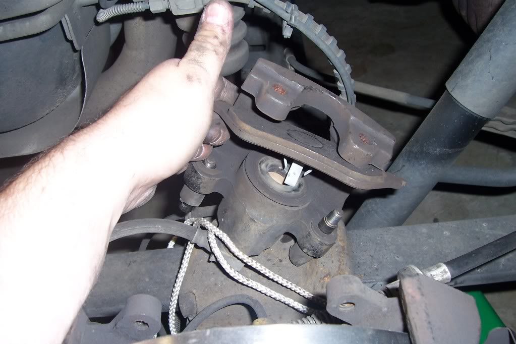
step 11
remove the inboard brake pad
step 12,
reinstall brake pads
you can put the anti squall grease on the back side of the pads if you like on just the metal parts that make metal to metal contact,
also grease the 7mm caliper bolts with caliper grease
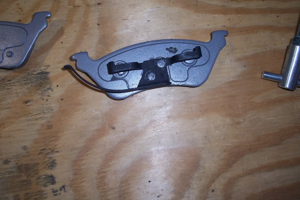
with my brake pads the both in-board pads were the same, but my out-board pads Had R and L marks on them so let you know which side they went
step 13
reinstall the caliper, this part takes some force, you start by in stalling the side that has the metal spring tab in, (hint, make sure the caliper bolts are pulled out a bit so they are not getting hung up when trying to push the caliper on)
step 14
Tighten the 7mm Allen bolts to 26 ft/lbs
put tire on, snugging the lugs, Lower van and do other side
after finishing other side and lowering van, tighten Lugs to 95 ft/lbs
step 15
bleed brakes, starting at DR, PF, PR, DF using your 3/8 brake bleeder wrench
here is some pics and my advice, so use according to your own ability and at your own risk
warning, so brake materials might contain asbestos so you may want to use gloves, mask and eye protection for safety
it took me 45mins for the first side(taking pics)
2nd side took 25mins
then 20mins bleeding brakes
things you will Need
7mm Allen wrench socket
brake cleaner (I used 1 1/2 cans)
rotors,
pads
3/8 box wrench for bleeding the brakes
Dot 3 brake fluid
optional but I used,
caliper grease
and anti squeal grease
step 1
park the van on level surface, block the both sides of the front tires to prevent rolling
Loosen the Lug nuts
Make sure the Parking brake is Off
step 2
Jack up the back tire, (I only did one at a time) place it on jack stands
remove the tire
step 3
remove the two 7mm Allen head bolts
step 4
press the one side of the caliper up (press on the side opposite the metal spring type tab) takes a little force to get it loose, then it comes up freely
step 5
secure the caliper so that it is not hanging on the brake hose
step 6
remove the rotors
they should pull right off, my first one came off easily
but the other side had never been removed, it still had a clip to hold the rotor on, simply remove it and discard it, that rotor I had to work to get off due to rust, I used a rubber mallet and whacked it along the center hub and on the back of the rotor being carefully not to hit anything else
step 7
then I sprayed everything off with brake cleaner, being careful not to hit the rubber brake line
also when cleaning after that rotor came off I notice a slight build up off rust along the center hub, so I gently scrapped it off
step 8
take the new rotor and spray it off with brake cleaner to get the packing oil off,
then simply slide it on to the wheel studs
step 9
press down on the outboard side of the brake pad (it takes some pressure to get it to separate, then simply pull the pad off
step 10
using the brake caliper compression tool on top of the old inboard brake pad, Slowly compress the brake caliper, you will want to keep an eye on the master cylinder to make sure it does not over flow, you may have to remove some fluid so it does not over flow
( I personally opened the brake bleeder valve just a crack to help)
step 11
remove the inboard brake pad
step 12,
reinstall brake pads
you can put the anti squall grease on the back side of the pads if you like on just the metal parts that make metal to metal contact,
also grease the 7mm caliper bolts with caliper grease
with my brake pads the both in-board pads were the same, but my out-board pads Had R and L marks on them so let you know which side they went
step 13
reinstall the caliper, this part takes some force, you start by in stalling the side that has the metal spring tab in, (hint, make sure the caliper bolts are pulled out a bit so they are not getting hung up when trying to push the caliper on)
step 14
Tighten the 7mm Allen bolts to 26 ft/lbs
put tire on, snugging the lugs, Lower van and do other side
after finishing other side and lowering van, tighten Lugs to 95 ft/lbs
step 15
bleed brakes, starting at DR, PF, PR, DF using your 3/8 brake bleeder wrench
Veteran
Joined: Feb 2010
Posts: 309
Likes: 3
From: va
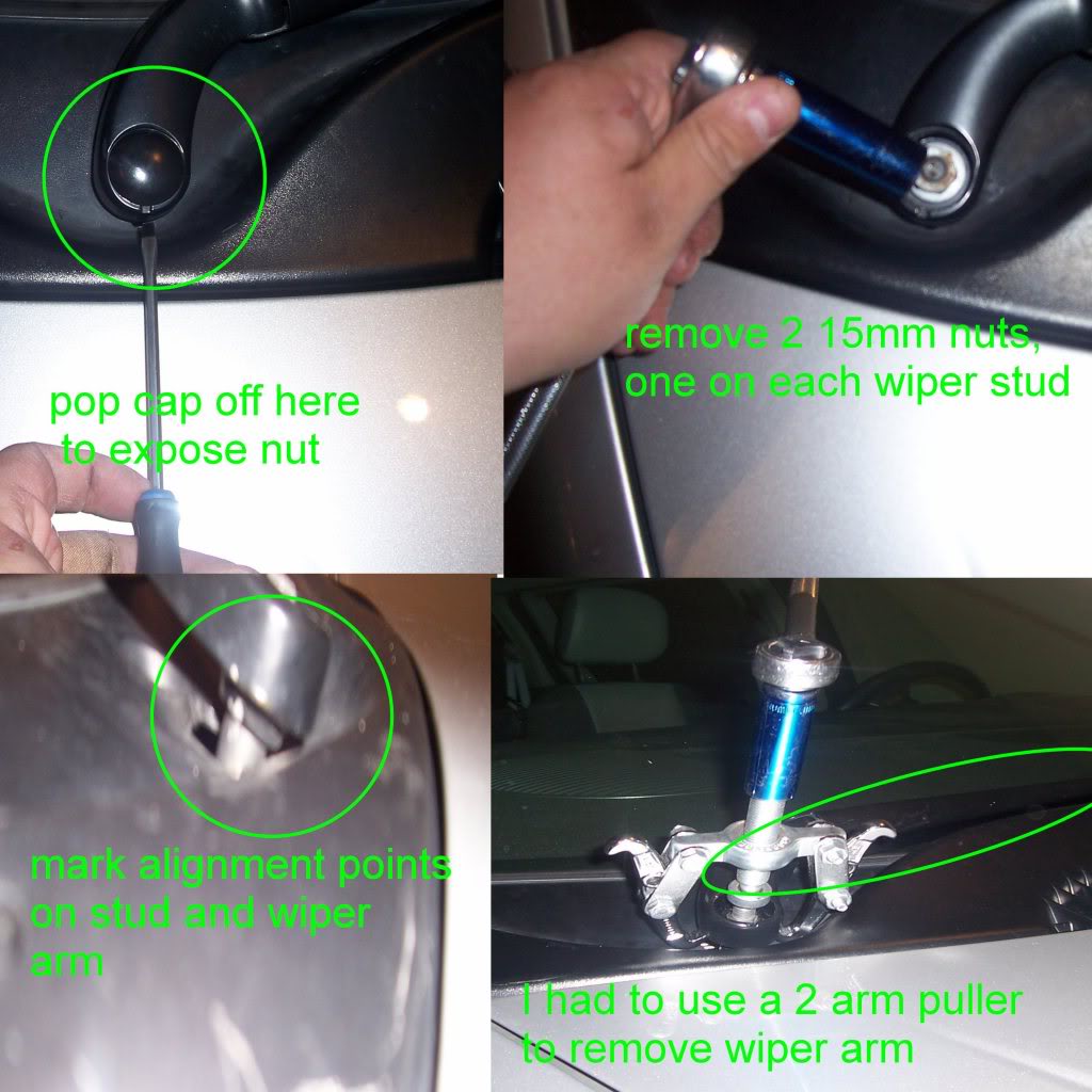
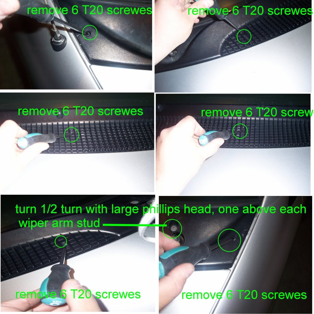
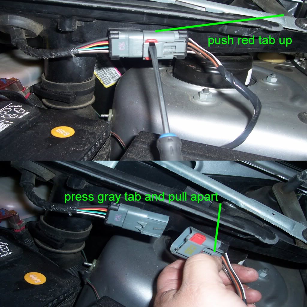
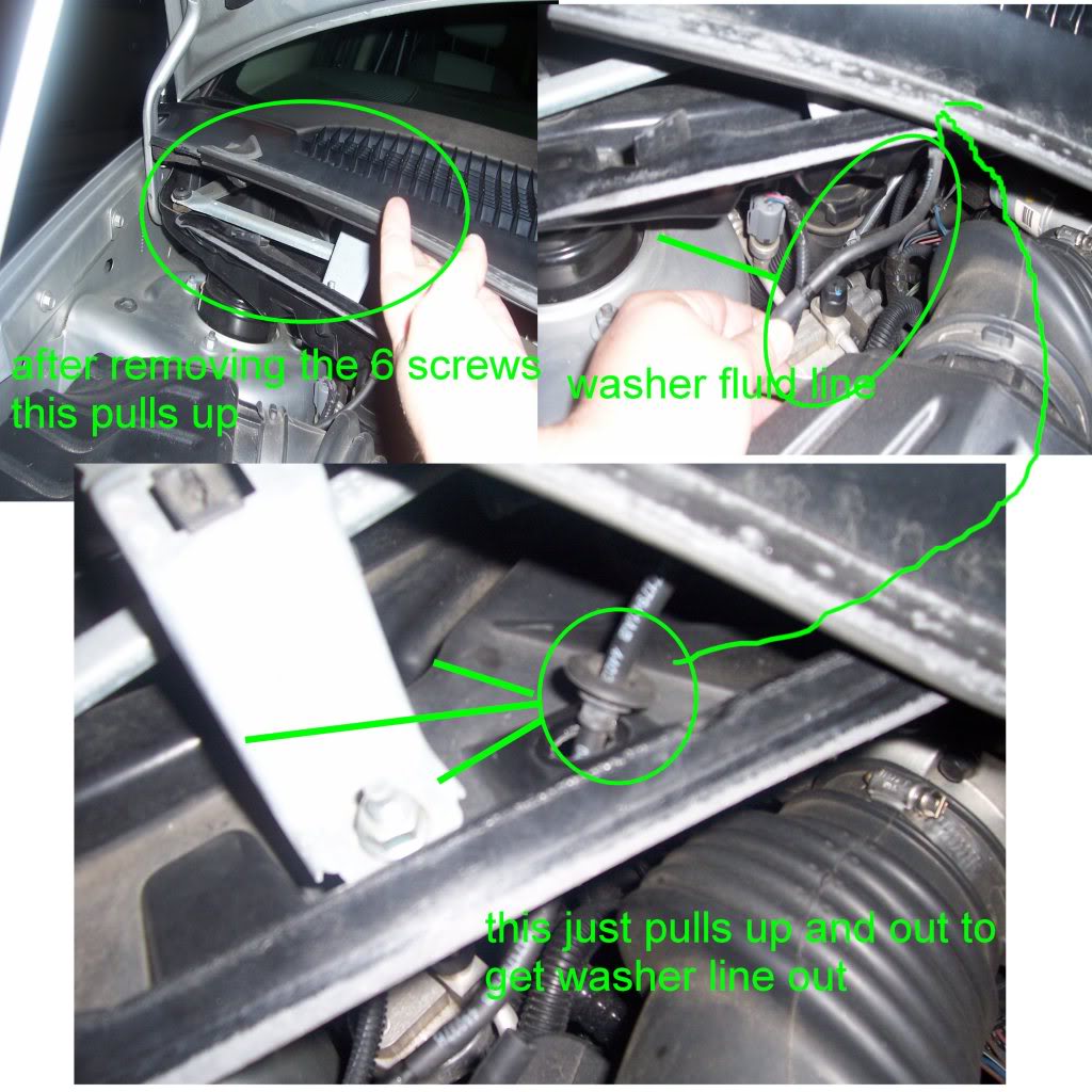
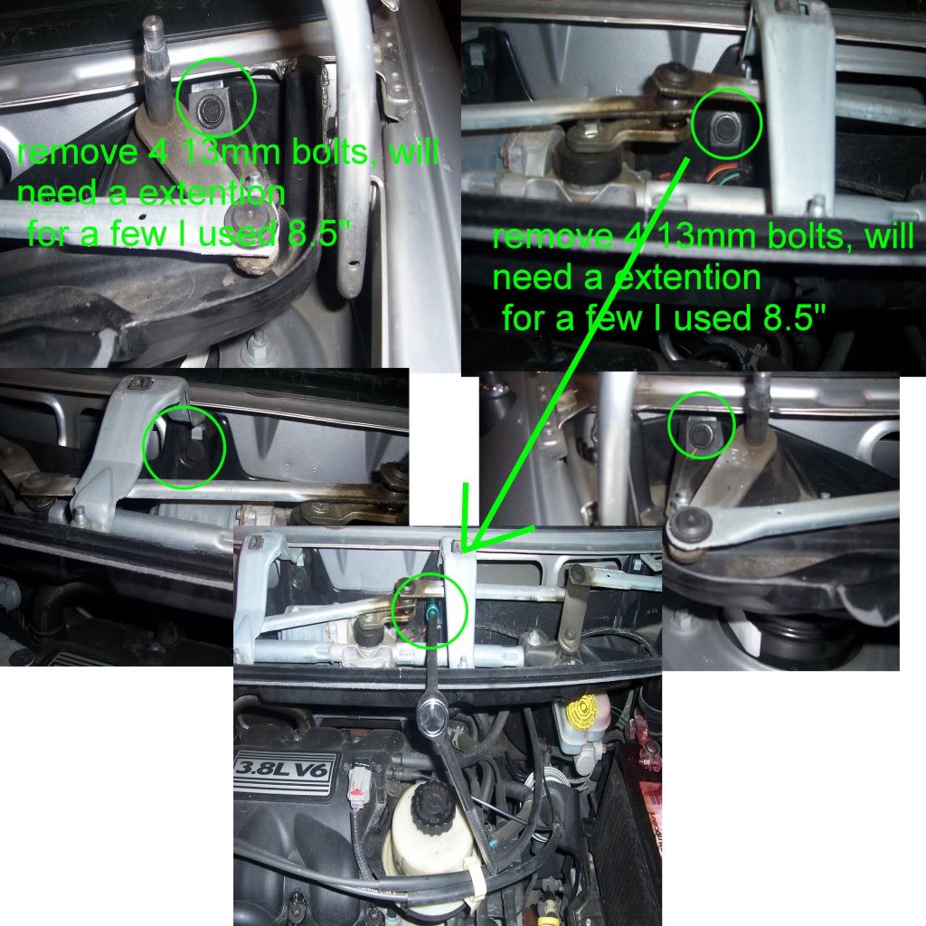
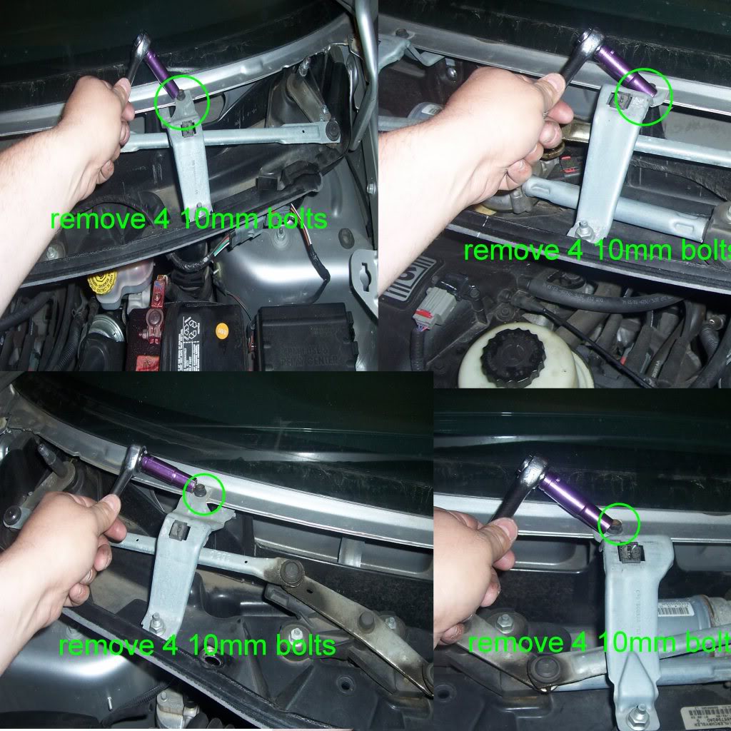
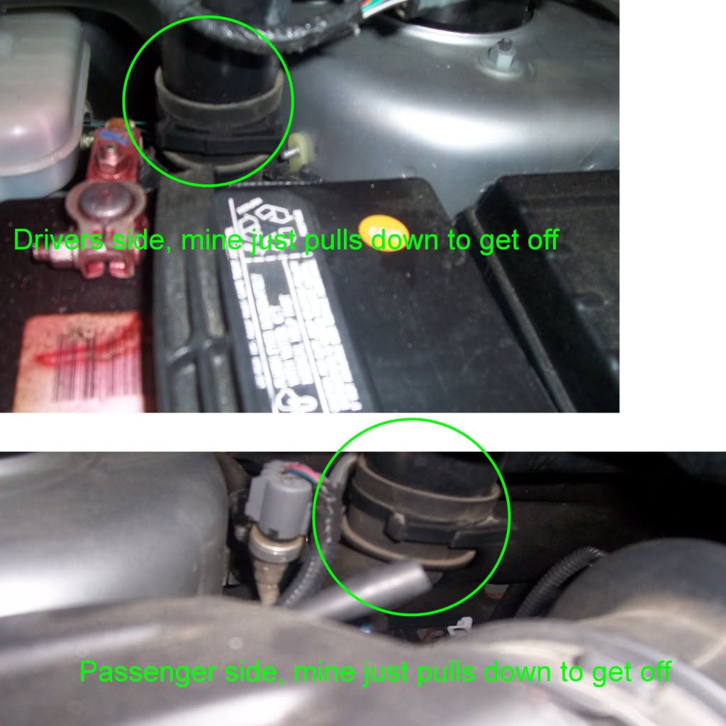
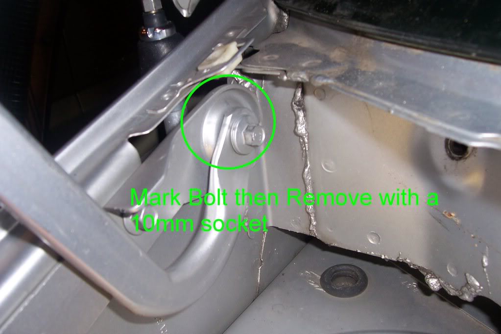
how to remove wiper crowl
this is on my 2006 DGC, takes about 15mins to take off, gives alot more room on the back side if needed
15mm socket
13mm socket
10mm socket
small screw driver
2-arm puller (got mine from Harbor Freight 3pc set, smallest size in the set is what I used)
8" or larger extention
T-20 screw driver
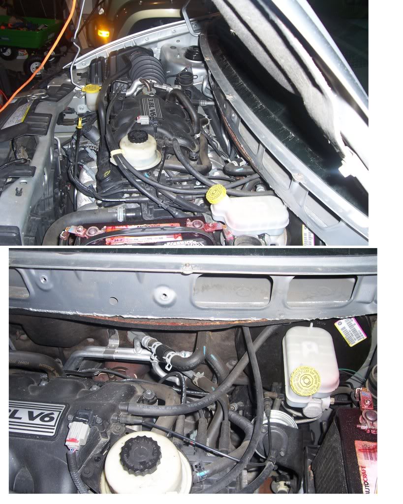
if you want to remove the hood for even more room
Notice how much more room there is
this is on my 2006 DGC, takes about 15mins to take off, gives alot more room on the back side if needed
15mm socket
13mm socket
10mm socket
small screw driver
2-arm puller (got mine from Harbor Freight 3pc set, smallest size in the set is what I used)
8" or larger extention
T-20 screw driver
if you want to remove the hood for even more room
Notice how much more room there is
Veteran
Joined: Feb 2010
Posts: 309
Likes: 3
From: va
How To Upload Pictures on this site
first you have to upload a free service like http://photobucket.com/ or any other picture upload service
the reason you should do this is that this site has a limited upload space, so you will only be able to add 1-2 pictures at most
once files are uploaded at photobucket
as you are viewing the thumbnails view of your pictures then just move you mouse over the pic you want and it will expand to show 4 links,
you will want to copy the Direct Link

then come back to this site and in the thread where you are posting the picture, click this button and input the link you just copied

the key thing with photobucket pictures is to copy the Direct Link
no matter which view is showing
(important note: after adding the pics to the upload site, file them how/where you want them before adding them here, since if you move the picture on photobucket/upload site, they it will no longer show up here,)
first you have to upload a free service like http://photobucket.com/ or any other picture upload service
the reason you should do this is that this site has a limited upload space, so you will only be able to add 1-2 pictures at most
once files are uploaded at photobucket
as you are viewing the thumbnails view of your pictures then just move you mouse over the pic you want and it will expand to show 4 links,
you will want to copy the Direct Link
then come back to this site and in the thread where you are posting the picture, click this button and input the link you just copied
the key thing with photobucket pictures is to copy the Direct Link
no matter which view is showing
(important note: after adding the pics to the upload site, file them how/where you want them before adding them here, since if you move the picture on photobucket/upload site, they it will no longer show up here,)
OVERHEAD CONSOLE
Any diagnosis of the overhead console should begin with the use of the DRB III� diagnostic tool. For information on the use of the DRB III�, refer to the appropriate Diagnostic Procedures information.
If the problem with the overhead console is an inaccurate or dashed (- -) display, refer to SELF-DIAGNOSTIC TEST. If the problem with the overhead console is incorrect Vacuum Fluorescent Display (VFD) dimming levels, use a DRB III� scan tool and the proper diagnostic procedures information to test for the correct dimming message inputs being received from the Body Control Module (BCM) or Front Control Module (FCM) over the Programmable Communications Interface (PCI) data bus circuit. If the problem is a no-display condition, use the following procedures.
Inspect the related wiring harness connectors for broken, bent, pushed out, or corroded terminals. Refer to the appropriate wiring information.
Check the fused B(+) fuse in the integrated power module. If OK, go to Step 2. If not OK, repair the shorted circuit or component as required and replace the faulty fuse.
Check for battery voltage at the fused B(+) fuse in the integrated power module. If OK, go to Step 3. If not OK, repair the open fused B(+) circuit to the fused B(+) fuse in the integrated power module as required.
Check the fused ignition switch output (run/start) fuse in the integrated power module. If OK, go to Step 4. If not OK, repair the shorted circuit or component as required and replace the faulty fuse.
Turn the ignition switch to the On position. Check for battery voltage at the fused ignition switch output (run/start) fuse in the integrated power module. If OK, go to Step 5. If not OK, repair the open fused ignition switch output (run/start) circuit to the ignition switch as required.
Turn the ignition switch to the Off position. Disconnect and isolate the battery negative cable. Remove the overhead console. Check for continuity between the ground circuit cavity of the roof wire harness connector for the electronics module and a good ground. There should be continuity. If OK, go to Step 6. If not OK, repair the open ground circuit as required.
Connect the battery negative cable. Check for battery voltage at the fused B(+) circuit cavity of the roof wire harness connector for the electronics module. If OK, go to Step 7. If not OK, repair the open fused B(+) circuit to the fused B(+) fuse in the integrated power module as required.
Turn the ignition switch to the On position. Check for battery voltage at the fused ignition switch output (run/start) circuit cavity of the roof wire harness connector for the electronics module. If OK, refer to SELF-DIAGNOSTIC TEST. If not OK, repair the open fused ignition switch output (run/start) circuit to the fuse in the integrated power module as required.
SELF-DIAGNOSTIC TEST
A self-diagnostic test is used to determine that the electronics module is operating properly, and that all the PCI data bus messages are being received for initial operation. Initiate the self-diagnostic test as follows:
With the ignition switch in the Off position, on Electronic Vehicle Information Center (EVIC) and Compass Mini-Trip Computer (CMTC) equipped vehicles simultaneously depress and hold the STEP and the RESET buttons. On Compass Temperature Module (CT) equipped vehicles depress the C/T and the US/M push buttons.
Turn the ignition switch to the On position.
Following completion of these tests, the electronics module will display one of the following messages:
Pass Self Test (EVIC only), PASS (CT, CMTC) - The electronics module is working properly.
Failed Self Test (EVIC only), FAIL (CT, CMTC) - The electronics module has an internal failure. The electronics module is faulty and must be replaced.
NOTE: If the compass functions, but accuracy is suspect, it may be necessary to perform a variation adjustment. This procedure allows the compass unit to accommodate variations in the earth's magnetic field strength, based on geographic location. NOTE: If the compass reading display is blank and only “CAL” appears in the display, demagnetizing may be necessary to remove excessive residual magnetic fields from the vehicle.
SUBJECT:
Evaporator Hiss Sound
OVERVIEW:
This bulletin involves installing an evaporator inlet flow straightener and a rubber
evaporator insert between the evaporator tubes if necessary.
MODELS:
2002 - 2003 (RS) Town & Country/Caravan/Voyager
NOTE: THIS BULLETIN APPLIES TO VEHICLES EQUIPPED WITH MANUAL
SINGLE ZONE HVAC (SALES CODE HAA) BUILT MARCH 25, 2002 (MDH 0325XX)
THROUGH AND INCLUDING FEBRUARY 26, 2003 (MDH 0226XX) OR MANUAL
DUAL ZONE HVAC (SALES CODE HAD) BUILT JULY 22, 2002 (MDH 0722XX)
THROUGH AND INCLUDING FEBRUARY 26, 2003 (MDH 0226XX).
SYMPTOM/CONDITION:
Some customers may experience a "hiss" sound, that originates from the Heating,
Ventilation, Air Conditioning (HVAC) unit. This may be most noticeable when
operating between 18 C - 27 C (65 F - 80 F).
DIAGNOSIS:
Operate the vehicle in a moderate ambient temperature, 18 C - 27 C (65 F - 80 F).
Run the HVAC system in recirculation, panel mode, A/C off, full heat, high blower for
1 to 2 minutes to heat the evaporator. Switch the HVAC system to outside air, panel
mode, A/C on, full cool, low blower, and maintain a steady engine speed of approximately
2000 rpm. Listen for a "hiss" that will occur when the A/C clutch cycles on.
NOTE: PERFORM THIS PROCEDURE AFTER EACH REPAIR TO THE HVAC
SYSTEM, TO VERIFY THE “HISS” IS NO LONGER PRESENT.
PARTS REQUIRED:
Qty. Part No. Description
AR (1) 04885713AA Flow Straightener, Evaporator Inlet
AR (1) 05061454AA Rubber Evaporator Insert