


Valve adjustment DIY


Thread Starter
|
Veteran
Joined: Mar 2007
Posts: 346
Likes: 0
From: Hill AFB, Utah
This is how to adjust the valves on a 3rd gen CTD. 1st and second gens should be similiar, they just have half as many valves to adjust
I am going to go through this as if you don't have the manual available. The manual says that valve adjustment is only required every 150K, but mine had one loose valve at only 68K on the clock. After 1 hour of work, the offending valve was adjusted and now runs as quiet as a CTD can
Before you begin, the engine must be under 100 degrees. I wouldn't attempt this if it has been running inthe last 6 hours.
On my engine label the valve specs are listed.
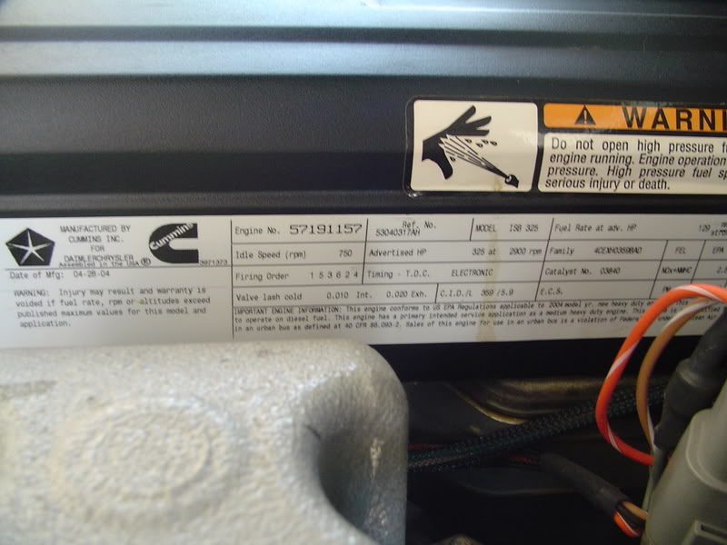
The intake valves are set to .010" and the exhaust valves are set to .020". The manual states that if the intake valves are between .006" and .015" that they are within spec and don't require adjustment. The exhaust valves don't require adjustment if they are between .015" and .030".
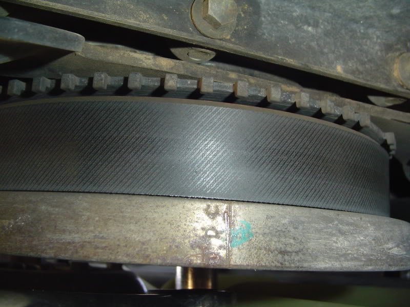
Lets get started. The first step is to set the engine to top dead center. There is a mark on the crankshaft pulley that you want on top (closest to the hood).
Here is a pic of the mark. I scraped it out with a scribe to make it a little more visible and mine has a green dot next to it. This pic was taken from underneath the truck to clearly see the mark. In this pic you can see it says TDC which wasn't legible when I was under the truck[:@] There are no other marks on the pulley.
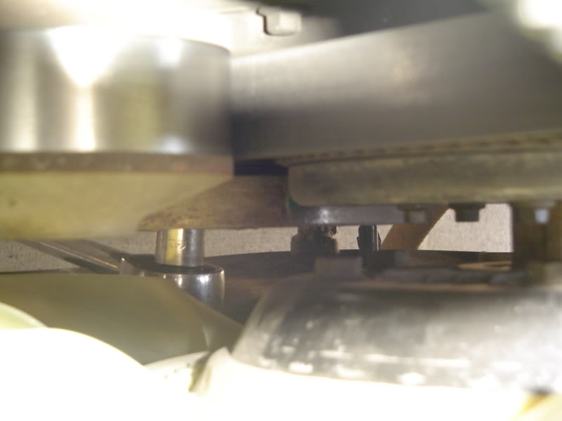
You will need to turn the engine so that this mark points straight up. This is what you want to see from the top.
Its hard to see but the mark is next to the green dot. This picture was taken looking down from the top next to the radiator cap on the passenger side. There is no pointerto line it up with, just make sure it is on the top of the pulley.
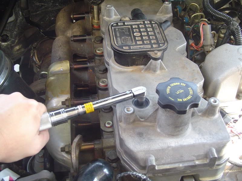
To turn the engine over, I found that a 15mm socket on a long 1/2" drive ratchet works best. There are 4 15mm bolts that hold the pully on and any one of them will turn the engine over. Just make sure you go slow and the ratcheting action will let you turn the pulley all the way around without repositioning it. The compression of the engine requires you to turn slowly, if you go to fast, it will kick back and you may hurt yourself.
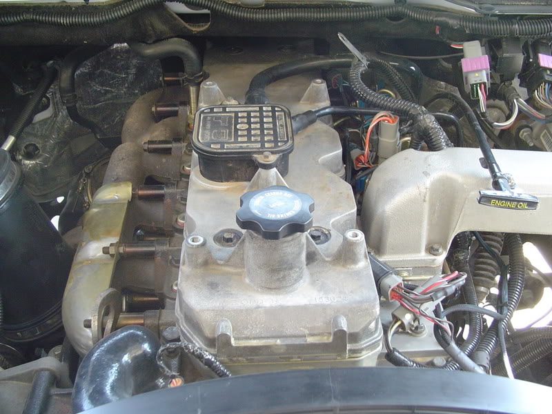
Now that we are at TDC, start pulling the valve covers. Remove the oil filler cap.
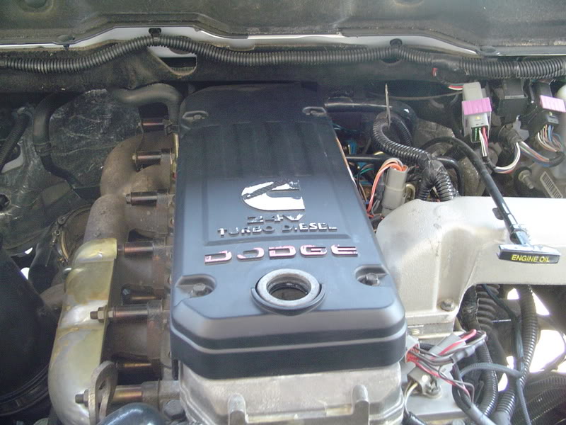
Then remove the 4 bolts that hold the cover on with a 10mm socket and this is what you'll see. I put the oil cap back on to keep dirt out during the next step.
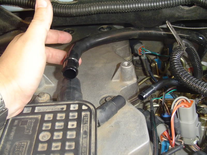
Pull the crankcase vent hoses out of the breather assembly. They are pretty tight in there and require a lot of twisting and pulling to get them out. (quiet Mayfair)
I am going to go through this as if you don't have the manual available. The manual says that valve adjustment is only required every 150K, but mine had one loose valve at only 68K on the clock. After 1 hour of work, the offending valve was adjusted and now runs as quiet as a CTD can
Before you begin, the engine must be under 100 degrees. I wouldn't attempt this if it has been running inthe last 6 hours.
On my engine label the valve specs are listed.
The intake valves are set to .010" and the exhaust valves are set to .020". The manual states that if the intake valves are between .006" and .015" that they are within spec and don't require adjustment. The exhaust valves don't require adjustment if they are between .015" and .030".
Lets get started. The first step is to set the engine to top dead center. There is a mark on the crankshaft pulley that you want on top (closest to the hood).
Here is a pic of the mark. I scraped it out with a scribe to make it a little more visible and mine has a green dot next to it. This pic was taken from underneath the truck to clearly see the mark. In this pic you can see it says TDC which wasn't legible when I was under the truck[:@] There are no other marks on the pulley.
You will need to turn the engine so that this mark points straight up. This is what you want to see from the top.
Its hard to see but the mark is next to the green dot. This picture was taken looking down from the top next to the radiator cap on the passenger side. There is no pointerto line it up with, just make sure it is on the top of the pulley.
To turn the engine over, I found that a 15mm socket on a long 1/2" drive ratchet works best. There are 4 15mm bolts that hold the pully on and any one of them will turn the engine over. Just make sure you go slow and the ratcheting action will let you turn the pulley all the way around without repositioning it. The compression of the engine requires you to turn slowly, if you go to fast, it will kick back and you may hurt yourself.
Now that we are at TDC, start pulling the valve covers. Remove the oil filler cap.
Then remove the 4 bolts that hold the cover on with a 10mm socket and this is what you'll see. I put the oil cap back on to keep dirt out during the next step.
Pull the crankcase vent hoses out of the breather assembly. They are pretty tight in there and require a lot of twisting and pulling to get them out. (quiet Mayfair
)
Thread Starter
|
Veteran
Joined: Mar 2007
Posts: 346
Likes: 0
From: Hill AFB, Utah
Push the vent hoses out of the way, I push them over behind the injector wiring and they stay put.
Next clean off the cover and the rubber seals on the bolts that hold the cover on. I do my best to keep as much dirt out of the engine as I can.
I wiped everything off and then blew the dust off of everything with compressed air.
This is what mine looked like before blowing the dirt off.
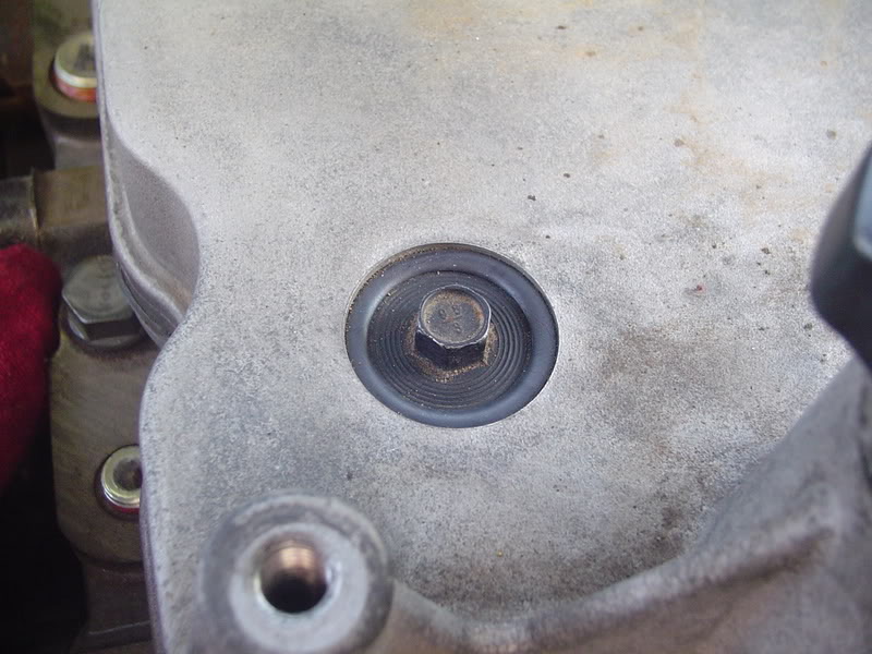
Once everything is clean, loosen up all 6 bolts until they will come out. I leave them in the holes to keep them clean and keep dirt from falling in the engine.The cover will slide right out toward the front of the truck.
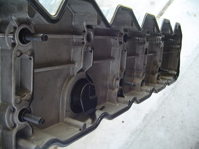
This is what the underside looks like. Make sure that spring stays in the cover and take this time to inspect the gasket for cuts and make sure it is still in its groove. Don't ask me what that spring does.
Now we can actually adjust the valves. If both number 1 rocker arms are loose then we can begin. If they aren't, rotate the crankshaft 1 full revolution and position the mark back at the top. This should put the #1 cylinder at top dead center.
The short rocker arms are the intake valves and the longer arms are for the exhaust valves.
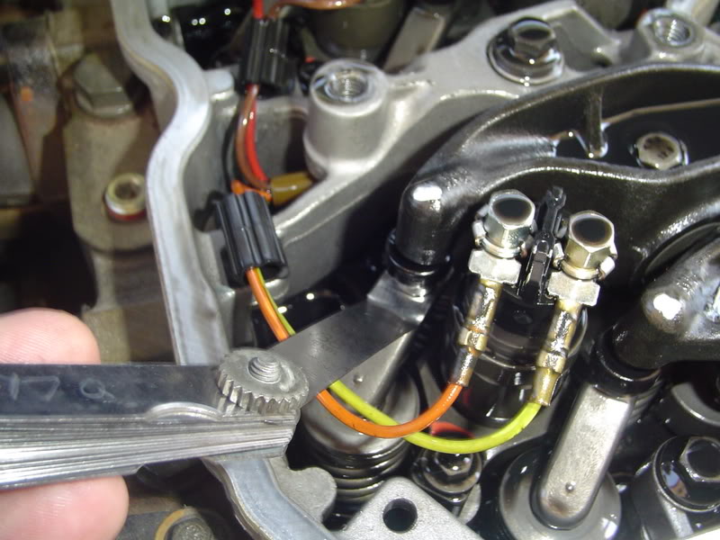
Insert the .006" feeler gauge between the rocker arm socket and crosshead. It should go in easily.
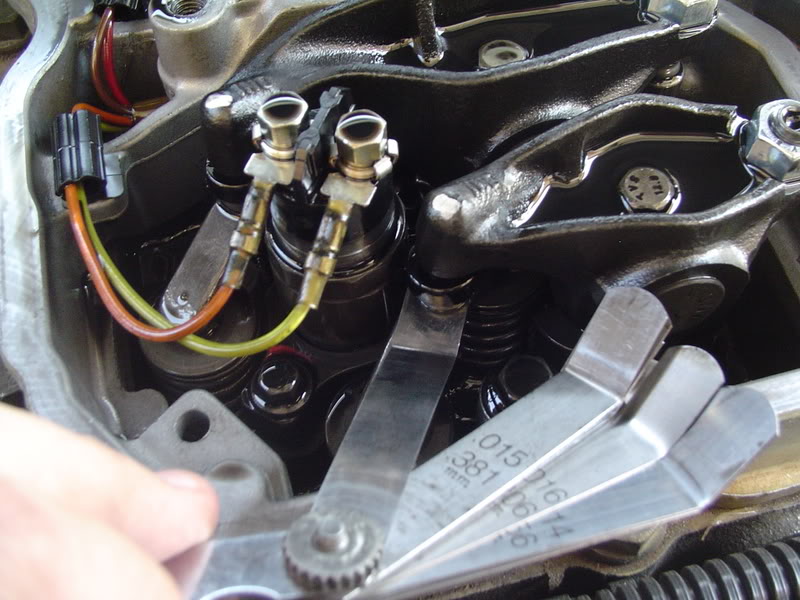
Be aware that the surface tension of the oil tends to stick the two together and can make it a little tricky to get in there. Then try to get the .015" feeler gauge in the same spot. Do not try to force it in there, if it slides in easily then the gap is too large.
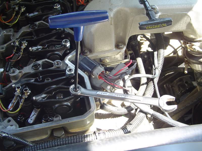
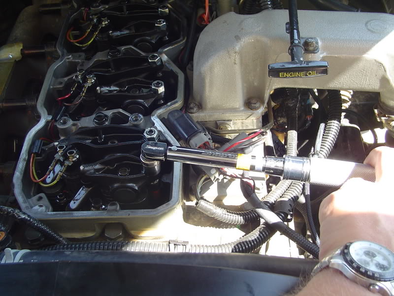
If the .006" doesn't go in OR the .015" does go in, then adjustment is required. Lossen the 9/16" lock nut and use an allen wrench to adjust the gap to .010". Adjust the allen screw until the .010" feeler gaugejust drags as you push/pull it through the gap. Then hold the allen wrench steady and tighten the jamb nut to 18 ft lbs. If you have done this right, the .010" feeler gauge should have a little resistance as you drag it through the gap,but a .011" feeler gauge should not go in without forcing it.
The exhaust valves are checked/adjusted the same way, but have a minimun of .015" and max of .030". If adjustment is necessary, set them to .020" using the same procedures.
With the engine in this position, adjust the intake valves of cylinders 1, 2 & 4 and adjust the exhaust valves on #1, 3 & 5. *Remember #1 is closest to the radiator and #6 is closest to the firewall.
Next clean off the cover and the rubber seals on the bolts that hold the cover on. I do my best to keep as much dirt out of the engine as I can.
I wiped everything off and then blew the dust off of everything with compressed air.
This is what mine looked like before blowing the dirt off.
Once everything is clean, loosen up all 6 bolts until they will come out. I leave them in the holes to keep them clean and keep dirt from falling in the engine.The cover will slide right out toward the front of the truck.
This is what the underside looks like. Make sure that spring stays in the cover and take this time to inspect the gasket for cuts and make sure it is still in its groove. Don't ask me what that spring does.
Now we can actually adjust the valves. If both number 1 rocker arms are loose then we can begin. If they aren't, rotate the crankshaft 1 full revolution and position the mark back at the top. This should put the #1 cylinder at top dead center.
The short rocker arms are the intake valves and the longer arms are for the exhaust valves.
Insert the .006" feeler gauge between the rocker arm socket and crosshead. It should go in easily.
Be aware that the surface tension of the oil tends to stick the two together and can make it a little tricky to get in there. Then try to get the .015" feeler gauge in the same spot. Do not try to force it in there, if it slides in easily then the gap is too large.
If the .006" doesn't go in OR the .015" does go in, then adjustment is required. Lossen the 9/16" lock nut and use an allen wrench to adjust the gap to .010". Adjust the allen screw until the .010" feeler gaugejust drags as you push/pull it through the gap. Then hold the allen wrench steady and tighten the jamb nut to 18 ft lbs. If you have done this right, the .010" feeler gauge should have a little resistance as you drag it through the gap,but a .011" feeler gauge should not go in without forcing it.
The exhaust valves are checked/adjusted the same way, but have a minimun of .015" and max of .030". If adjustment is necessary, set them to .020" using the same procedures.
With the engine in this position, adjust the intake valves of cylinders 1, 2 & 4 and adjust the exhaust valves on #1, 3 & 5. *Remember #1 is closest to the radiator and #6 is closest to the firewall.
Thread Starter
|
Veteran
Joined: Mar 2007
Posts: 346
Likes: 0
From: Hill AFB, Utah
Now rotate the crankshaft 1 revolution and put the mark back on top. You are now ready to adjust the intake valves on # 3, 5, & 6 and the exhaust valves on # 2, 4, & 6.
Once you are done checking/adjusting the valves, double check that all of the jamb nuts are torqued to 18 ft lbs.
Put the cover back on and tighen down the 6 bolts evenly. If you tighten them unevenly, you may inadverntantly crack the cover. Torque the bolts to 18 ft lbs.
Reconnect the breather hoses and put the top cover back on. Torque the 4 bolts to 18 ft lbs and make sure to put the wire harness support under the aft drivers side bolt.
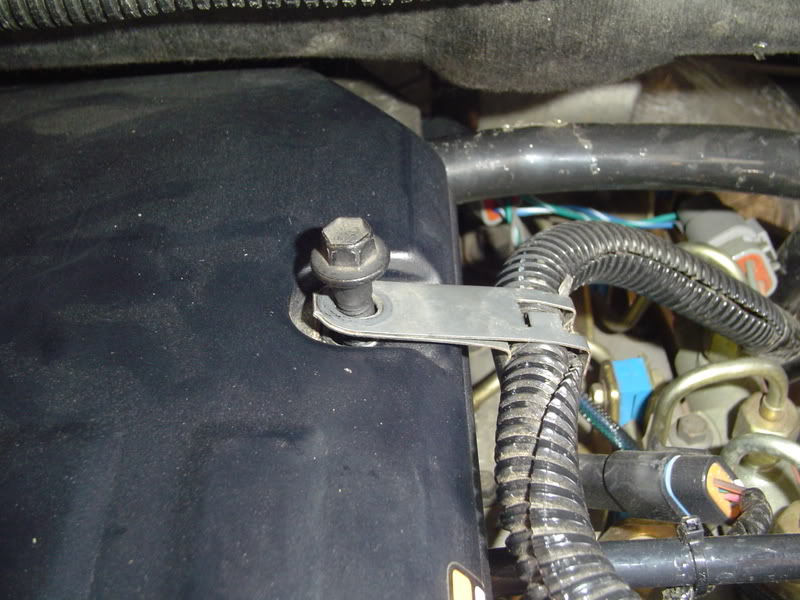
Put the oil cap back on and you shouldn't have to touch your valves for another 100K miles.
Once you are done checking/adjusting the valves, double check that all of the jamb nuts are torqued to 18 ft lbs.
Put the cover back on and tighen down the 6 bolts evenly. If you tighten them unevenly, you may inadverntantly crack the cover. Torque the bolts to 18 ft lbs.
Reconnect the breather hoses and put the top cover back on. Torque the 4 bolts to 18 ft lbs and make sure to put the wire harness support under the aft drivers side bolt.
Put the oil cap back on and you shouldn't have to touch your valves for another 100K miles.


Thread Starter
|
Veteran
Joined: Mar 2007
Posts: 346
Likes: 0
From: Hill AFB, Utah
No problemo.
I know some people are scared to death ofjobs like this, but it really is an easy job, and this is routine maintenance that all of our trucks occasionally need.
I know some people are scared to death ofjobs like this, but it really is an easy job, and this is routine maintenance that all of our trucks occasionally need.
Trending Topics


Champion
Joined: Feb 2006
Posts: 4,569
Likes: 0
From:
Good writeup, guess that saves me from having to do one
Just one word of advice to all. When you break the locknut loose to adjust the valves, back the adjustment all the way off, lift the rocker arm up and check the wear surfaces (expecially you guys with the 12v's. Check to see if there is any pitting on the valve stems and rocker faces). Guys with the 24v's when you go to adjust the valves after checking the wear surfaces, make damn sure the valve bridge is seated on both valves.
Just one word of advice to all. When you break the locknut loose to adjust the valves, back the adjustment all the way off, lift the rocker arm up and check the wear surfaces (expecially you guys with the 12v's. Check to see if there is any pitting on the valve stems and rocker faces). Guys with the 24v's when you go to adjust the valves after checking the wear surfaces, make damn sure the valve bridge is seated on both valves.
