

Siggie30- 89' vert build


Thread Starter
|
Captain

Joined: Oct 2010
Posts: 579
Likes: 1
From: Florida
Thanks, since I am still recovering from abdominoplasty things have slowed as far as the truck. I do odd things for about an hour at a time, so as not to "stress" my repairs. I actually sleeved the wires once, but undid them to modify some of the electronics. I also, cut the fuel pump and rear light wires by mistake, and will be going to the yard tomorrow to procure another light harness. As far as sleeving goes, I have found some stockish/generic wire loom. I find that the 3/4" is sufficient for the larger sections, and 1/2" and 3/8" for the other sections. Where the bulkhead connector is has been a bit more timely since I do not like to "coil" (+) leads and have debated how to properly clean up the area. I also have been soldering and heat shrinking every splice to make a worthy loom. It is dark, but I should take a few snaps soon, to show "worthwhile" progress. I use minimum 12 ga wire for all runs, and will run 4 ga alt/bat/starter leads with the apprpriate fusible link. Finding the right radiator hoses has been a pain since the difference between 1 1/4" and 1 3/8" really makes a difference.
Registered User
Joined: Sep 2010
Posts: 46
Likes: 0
From: Grand Rapids, MI
Wow Siggie...
1.) You have the best grammar of any forum user I've ever seen, and
2.) This project is awesome. I'm really impressed, however, I do think you'll need the newer style front end. If you can find a way by all means to keep that original front end though, do it - in my eyes, the newer fronts on the first generators do in fact look "cooler", but those original ones have a coolness of their own.
Keep up the good work man!
Thread Starter
|
Captain
Joined: Oct 2010
Posts: 579
Likes: 1
From: Florida
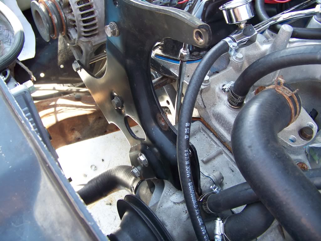
As promised, here are some updates. Of importance, I reused the factory bracket. Where the a/c compressor was, there is an a/c delete bracket that I will procure at the yard for ease of belt routing to not interfere with the water pump. Toward the end is the new harness being routed and cut. While not finished, it is for reference of which wires to keep from the "run" circuit. I will have to buy another battery as the one I had is too tired to be charged, and I haven't refreshed a battery in many years. If I have read the circuit diagram correctly, I may try starting it this afternoon, or tomorrow.
Stock accessory bracket
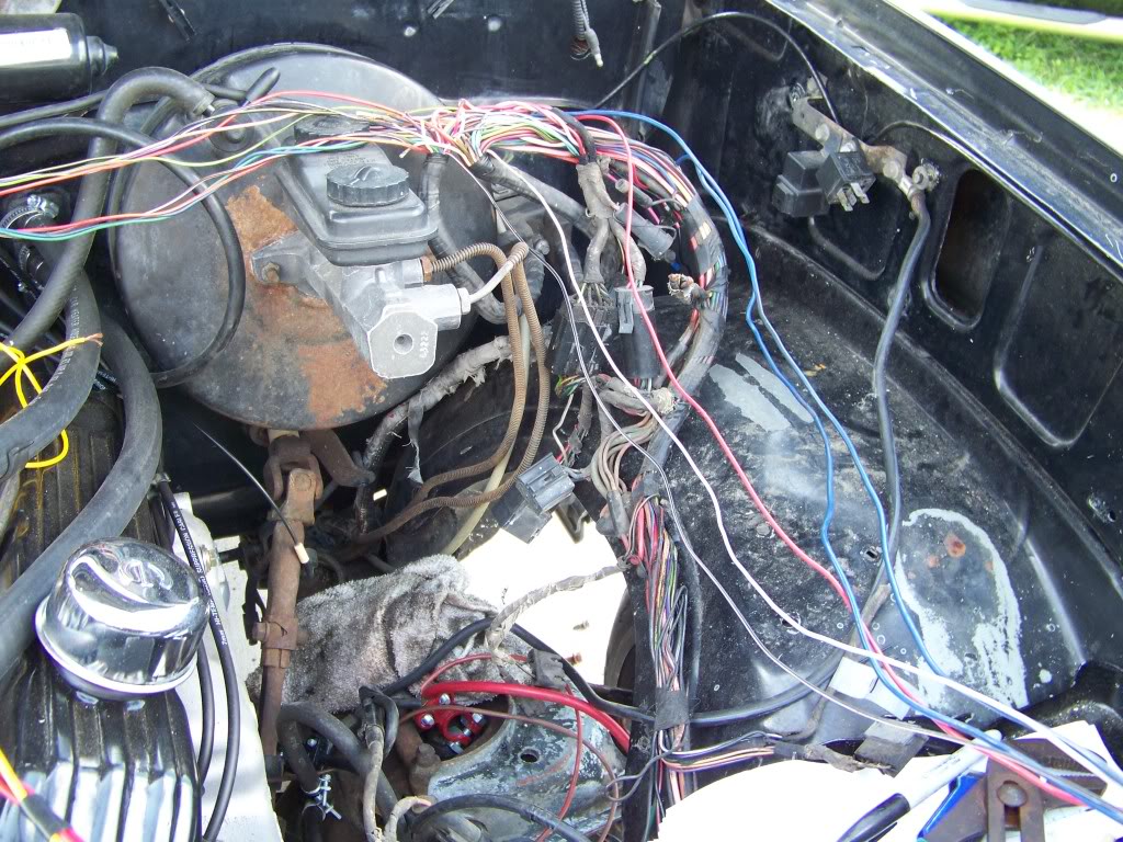
Engine management wiring prewrap
Power/relays and harness being cut yet again.
I may swap the fuel log around (aftermarket double pumper style) later to clean up the front engine hose routing, but the fuel pressure port will be upside down. For now it is fitted for informatics. It should be noted that the five wires to the right of the last picture are suppose to be: Red "B +", 2 blue "Run", white and black are also noted as being "Run", but possibly at lower voltage? The ceramic resistor can be deleted if using an internally regulated alternator. There are three that I know of from Denso (previously Nippon Denso or ND), but this one is original to the truck.
Stock accessory bracket
Engine management wiring prewrap
Power/relays and harness being cut yet again.
I may swap the fuel log around (aftermarket double pumper style) later to clean up the front engine hose routing, but the fuel pressure port will be upside down. For now it is fitted for informatics. It should be noted that the five wires to the right of the last picture are suppose to be: Red "B +", 2 blue "Run", white and black are also noted as being "Run", but possibly at lower voltage? The ceramic resistor can be deleted if using an internally regulated alternator. There are three that I know of from Denso (previously Nippon Denso or ND), but this one is original to the truck.
Last edited by siggie30; Apr 4, 2011 at 12:11 PM.
Thread Starter
|
Captain
Joined: Oct 2010
Posts: 579
Likes: 1
From: Florida
Okay, my camera battery is too low to take pics, but I will surely take some soon. I am trying to establish a relay for the fuel pump. I have kept the Grn/bk as a power lead, and the Bl/yl and Bl/rd for the level sender. My problem is the ground which I believe is the Gy (16 ga) and the Gy (18 ga). I do not recall my license plate lights ever working so I can only assume that there is a break in the line. I am going to piggy back the Gy/bk lead to a chassis ground and see if it is successful for the fuel pump after lunch. Either way the truck will have fuel today, even if I have to wire in an inline pump (which I am considering). Will post soon.
Also, the aforementioned wires in the previous post were deleted with the exception of the Blue wire which is indeed a "run" and the red which is a Bat.
Also, the aforementioned wires in the previous post were deleted with the exception of the Blue wire which is indeed a "run" and the red which is a Bat.
Thread Starter
|
Captain
Joined: Oct 2010
Posts: 579
Likes: 1
From: Florida
I surely will since my son has access to $20k digital cameras at his school instead of a camera phone or equivalent. I think I will post up an official writeup as well since it is obvious that there are none that encompass the swap in an entirety that incluse the electrical aspect. Speaking of which, it is apparent in hindsite that the earlier dakota's only have three relays pertinent to the engine (one of which is for A/C). One for the starter, second for the fuel pump, and the aforementioned a/c for the third. Also to note is I have traced all the wires from the bulkhead forward for future references which I will be happy to include in said write up.
Thread Starter
|
Captain
Joined: Oct 2010
Posts: 579
Likes: 1
From: Florida
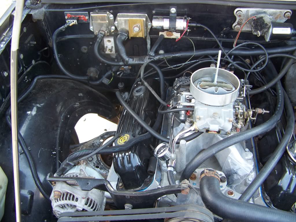
Someone had posted a question about wire loom wrapping. While I am not 100% this will give you an idea of routing and grouping wires. I may move the mopar ignition module to the fender well to "clean" the bay a bit, but I do not see the benefit at this time since the bay is not freshly painted. Also you may note the a/c delete bracket/ pulley to clear the water pump.

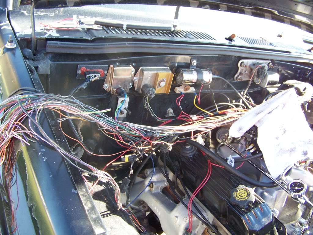
Obviously this last picture shows the very rough wire routing at the power points and firewall. I am still tracing 4 wires for the coolant sensor and the oil pressure sensor. After that I will start to "bind them" prior to covering them. If it is too scary for you, my recommendation is to not look at the whole loom, and concentrate on ONE WIRE at a time. The two relays are for the starter and the fuel pump relay.

Obviously this last picture shows the very rough wire routing at the power points and firewall. I am still tracing 4 wires for the coolant sensor and the oil pressure sensor. After that I will start to "bind them" prior to covering them. If it is too scary for you, my recommendation is to not look at the whole loom, and concentrate on ONE WIRE at a time. The two relays are for the starter and the fuel pump relay.