


Found This in My Diff

Administrator
Joined: Jul 2007
Posts: 24,686
Likes: 21
From: South Georgia/East Florida
Hell, just find you some damp grass and see if you tear up one spot or two... But the LSD will perform fine (well as fine as the POS stock LSD Chrysler uses does) without the clips. I've known guys who have run Rams with the clips pulled for 40k miles and still had LSD operation...
Hall Of Fame


Joined: Jun 2005
Posts: 14,228
Likes: 19
From: Riverton, UT
There are some misconceptions here I would like to address.
First off those clasps do not add pressure to the clutch packs. In fact the bevel springs flip the opposite way so to not apply pressure to them, so they only sit in the groves of the carrier. Each side of the clasp has that slight clip on it. If you break off the inside then the clasp can fall outward into the differential. From there is is usually picked up from the large ring gear and slung into the oil sump in the front that is used to lubricate the pinion bearing. Now once it gains access to the pinion bearing sump it is too big and cannot use oil flow to flush it's self out. So then it finds it's way into the bearing and BOOM! Seizes the pinon bearing then the energy is transferred to the ring gear and out to the housing. There goes the rear end and that usually means the housing breaks. However if the outer clasp broke then I think you might be ok for now, but you need to fix it. Here is that baffle:
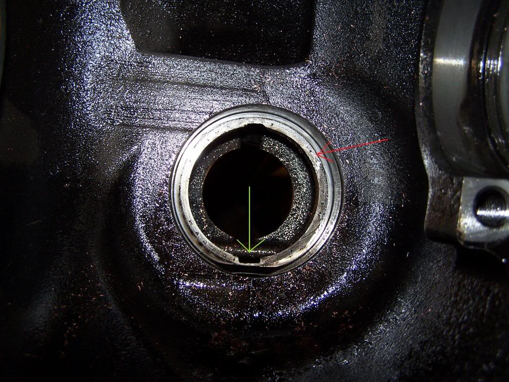
Red is the pinion/yoke bearing race, Green arrow is the sump. In fact you can see some of those metal particles in this picture mixed with copper from when the ABS sensor broke from the flying clasp in mine.
Problem is the clasp is a hardened steel that when the clutch pack tabs go to spin inside the carrier (LSD working) then the energy is then transferred from the tabs into the clasp. The clasp then transfers the torque into the body of the carrier. Now without the clasp the tabs of the clutch will dig into the carrier body until the carrier body finally fails and brakes.
Now this design is a shotty one to say the least, but is effective at it's job, just needed to be built better is all. Because the way the clasp is manufactured it is a basic clasp with each end crimped into a clasp, however there is only a small amount of metal left after the crimp and that is the reason they mainly fail.
Now on to the actual fix,
I don't know of a place you can just get the clasps. The 2 new clasps come in the new clutch kit for around $120 from places like www.sixstates.com or other companies. Now to actually fix the issue you can get the new clutch pack and while you have it out you just replace the clutch packs. At this point you can decide if you want to do a full rebuild or just leave it. Regardless, you have to pull the carrier to compress the bevel springs to remove the spiders so you can remove the clutch packs. To get the carrier out you have to remove the adjustable bearing cap. To do this without messing with backlash you can only back off one side, and to get to it you have to go down the axle housing (inside).
As for just pulling the clasps out and calling it a day, well I don't know if I would ever chance just that.
First off those clasps do not add pressure to the clutch packs. In fact the bevel springs flip the opposite way so to not apply pressure to them, so they only sit in the groves of the carrier. Each side of the clasp has that slight clip on it. If you break off the inside then the clasp can fall outward into the differential. From there is is usually picked up from the large ring gear and slung into the oil sump in the front that is used to lubricate the pinion bearing. Now once it gains access to the pinion bearing sump it is too big and cannot use oil flow to flush it's self out. So then it finds it's way into the bearing and BOOM! Seizes the pinon bearing then the energy is transferred to the ring gear and out to the housing. There goes the rear end and that usually means the housing breaks. However if the outer clasp broke then I think you might be ok for now, but you need to fix it. Here is that baffle:
Red is the pinion/yoke bearing race, Green arrow is the sump. In fact you can see some of those metal particles in this picture mixed with copper from when the ABS sensor broke from the flying clasp in mine.
Problem is the clasp is a hardened steel that when the clutch pack tabs go to spin inside the carrier (LSD working) then the energy is then transferred from the tabs into the clasp. The clasp then transfers the torque into the body of the carrier. Now without the clasp the tabs of the clutch will dig into the carrier body until the carrier body finally fails and brakes.
Now this design is a shotty one to say the least, but is effective at it's job, just needed to be built better is all. Because the way the clasp is manufactured it is a basic clasp with each end crimped into a clasp, however there is only a small amount of metal left after the crimp and that is the reason they mainly fail.
Now on to the actual fix,
I don't know of a place you can just get the clasps. The 2 new clasps come in the new clutch kit for around $120 from places like www.sixstates.com or other companies. Now to actually fix the issue you can get the new clutch pack and while you have it out you just replace the clutch packs. At this point you can decide if you want to do a full rebuild or just leave it. Regardless, you have to pull the carrier to compress the bevel springs to remove the spiders so you can remove the clutch packs. To get the carrier out you have to remove the adjustable bearing cap. To do this without messing with backlash you can only back off one side, and to get to it you have to go down the axle housing (inside).
As for just pulling the clasps out and calling it a day, well I don't know if I would ever chance just that.
Last edited by hydrashocker; Oct 7, 2011 at 11:18 PM.

Amateur
Joined: Oct 2011
Posts: 43
Likes: 0
When I removed the diff cover to drain it I found the same chunks of metal as in the photo on page one of this thread... so I did some investigating. Went and asked the guy at the local Dodge dealer parts counter... he told me exactly what they were and sold me a new pack of only the four clips for 16 bucks. I went back to the differential and removed the carrier (after making my own bearing adjustment tool) and completely disassembled all the carrier components for inspection. Everything seems to be unharmed except for some gouging of the main diff housing and the "bearing cap" (as i call it...the two halves that hold the carrier to the diff housing). The gouging was of course caused by one of the clutch clips working its way out... turned right into it like a lathe. The housing and cap might be ok though... I may have caught it in time. But the rest of the components look ok.. didn't remove the pinion gear but it looks perfect and turns smoothly. So after all this... I'm at the point of... do I put this all back together? with the new clips installed? or without? In my mind.... I can either try putting this all back together and see how much more I get out of this diff.... or.... get a reman axle with a better diff altogether. At this point I'm only into this thing for 16 bucks. If I have to go further... might as well go all the way. Thoughts?
Amateur
Joined: Oct 2011
Posts: 43
Likes: 0
Oh... forgot to mention that during my over-zealous slinging of wrenches getting this carrier out..... I just went ahead and took both carrier adjustment rings out too.. ha ha. I know I screwed up. I'm sure I'll come up with a few new cuss words trying to get it all back in and aligned. Thanks again for all your responses.

Here is some information on how to install the clutch pack if that is what you are doing.
ASSEMBLY
NOTE: The clutch discs are replaceable as complete sets only. If one clutch disc pack is damaged, both packs must be replaced.
Lubricate each component with gear lubricant before assembly.
Assemble the clutch discs into packs and secure disc packs with retaining clips Clutch Disc Pack .
Position assembled clutch disc packs on the side gear hubs.
Install clutch pack and side gear in the ring gear side of the differential case Clutch Discs & Lower Side Gear Installation Be sure clutch pack retaining clips remain in position and are seated in the case pockets.
Position the differential case on Side Gear Holding Tool 8136.
Install lubricated Step Plate 8139-2 in lower side gear Upper Side Gear & Clutch Disc Pack Installation .
Install the upper side gear and clutch disc pack Upper Side Gear & Clutch Disc Pack Installation
Hold assembly in position. Insert Threaded Adapter 8139-1 into top side gear.
Insert Forcing Screw C-4487-2.
Tighten forcing screw tool to slightly compress clutch discs.
Place pinion gears in position in side gears and verify that the pinion mate shaft holes are aligned.
Rotate case with Turning Bar C-4487-4 until the pinion mate shaft holes in pinion gears align with holes in case. It may be necessary to slightly tighten the forcing screw in order to install the pinion gears.
Tighten forcing screw to 122 N�m (90 ft. lbs.) maximum to compress the Belleville springs.
Lubricate and install thrust washers behind pinion gears and align washers with a small screw driver. Insert mate shaft into each pinion gear to verify alignment.
Remove Forcing Screw C-4487-2, Step Plate 8139-2, and Threaded Adapter 8139-1.
Install pinion gear mate shaft and align holes in shaft and case.
Install the pinion mate shaft lock screw finger tight to hold shaft during differential installation.
Lubricate all differential components with hypoid gear lubricant
Hall Of Fame
Joined: Jun 2005
Posts: 14,228
Likes: 19
From: Riverton, UT
I understand the way the clutch packs go together, however the placement of the bevel springs does not allow the claps to hold them together. Now if you flip the bevel springs backward there is a compression of the springs and the clasp will hold it together after the springs are being compressed in the clutch packs. The problem with this example is the bevel springs are backward facing on the gears. If someone has done this it will cause the clasps to have pressure on the sides and the crimped edge causing it to pop off after time.
Now if you read Master's statement:
It means that there is no compression clasps, instead they just sit on the clutch pack ends with no pressure. That is why you have to be very careful as it states to keep the packs together and the clasp as you slide them down in the carrier. So when it states:
That is not fully correct, because for it to actually "secure" them there would have to be pressure, and there isn't supposed to be or the bevel springs in the clutch packs are in backward.
There are 2 bevel springs in the clutch packs, one on each end. The one up behind the gear is supposed to press in the middle of the gear, meaning the ridge "High" end is supposed to push at the center, not at the outside. Now on the carrier side, the bevel spring should face to the inside just the same as the gear side, that way the pressure is pushed onto the clutch disk pack and not into the center. Again, the high inside of the bevel spring should face AWAY from the clutch pack on both sides so the outside of the bevel spring faces the face of the clutch packs.
It took a little ingenuity to figure this out because nothing is written to show the correct way, and yet the way they state it leave it open for interpretation. I've done a lot of rebuilding of gear boxes so I figured it out. I sould have taken a picture of exactly how they go together but I didn't. However I did take a few pic's of one of the bevel springs and clutch ring to show the wear. Now in this pic the bevel spring is on the left, and one of the clutch disks on the right. Now the bevel spring is facing it's cone down, and in this picture you can see the slightly shinny ring (the inner side) is where it wore on the gear back face:
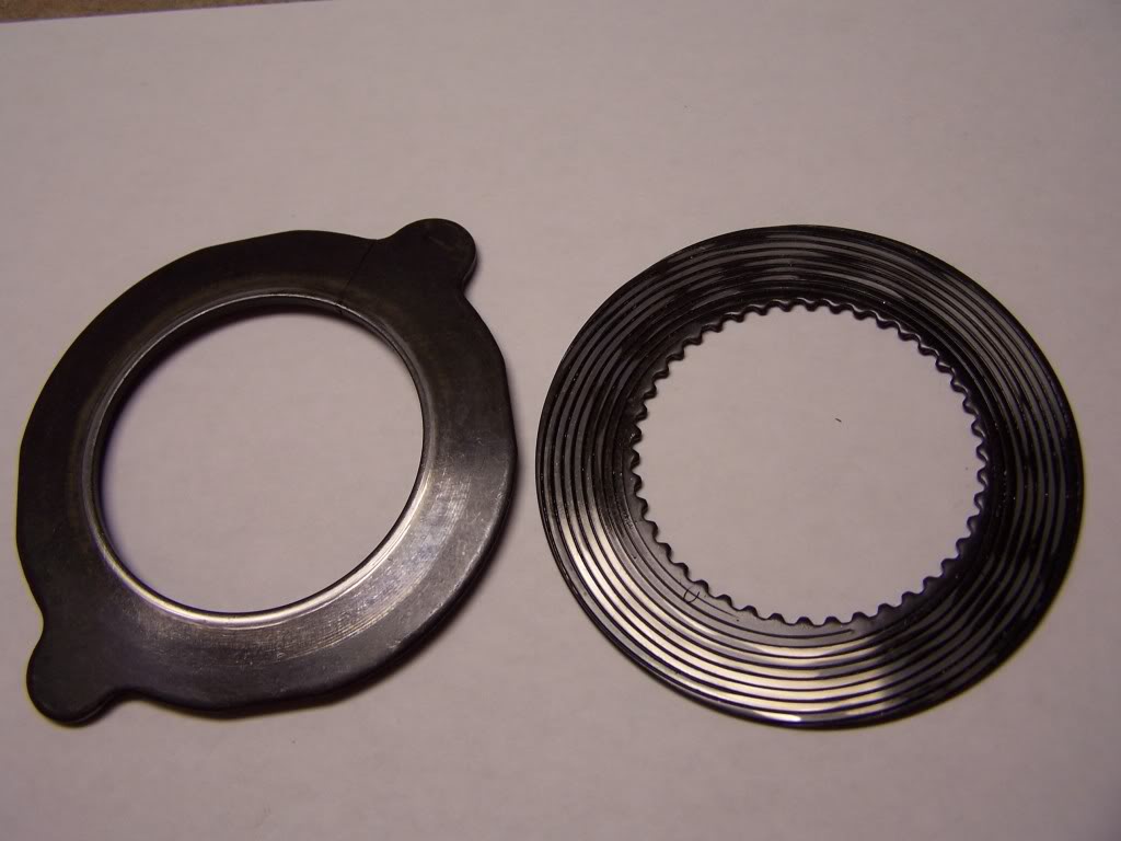
Now I flip the bevel spring over and now you can see the inside of the bevel spring with the worn edges that was compressing the clutch packs (this one is cracked and bad).
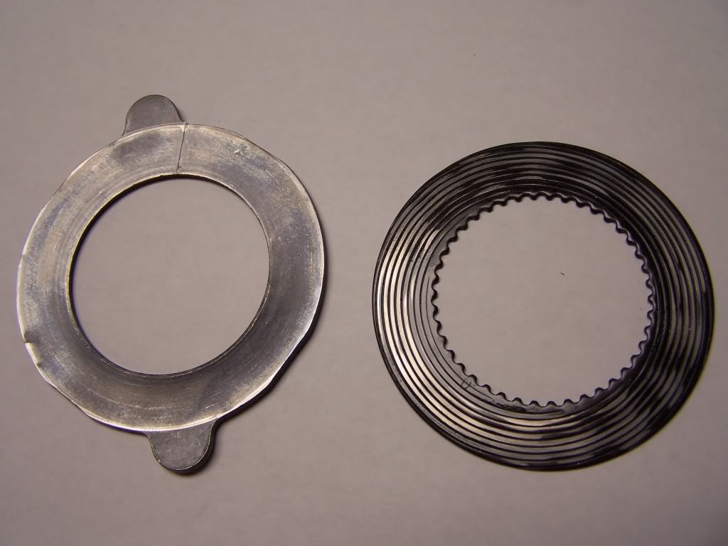
The bevel spring is a simple tempered washer, but one outside is larger then the inside so it is not flat, instead the outside is "Beveled" out from the inside, and when you compress them you direct pressure to either the inside of it or the outside. This direction of pressure is built to be focused to certain parts and that pressure is then focused to a face. This is why the clutch faces are toward the outside instead of the inside. Os you focus the pressure to the center and outsides of the clutch pack.
Blue<---- You should just put the old pack together with the new clasps. Slap it in and run it for now, or at least I would. While the carrier is out I would remove the pinion and clean out the oil sump that is under the pinion gear. Your right there just remove the pinion bolt, use a puller to remove the yoke, grasp out the crush sleave and then push the pinion out and have a look at it. Clean out the sump and if everything looks good put it back in. Then place the old crush sleeve back in, check the yoke seal, replace the yoke seal if bad or lubricate the yoke and seal face and slide the old yoke back in and tighten the pinion nut to inch pound specs for bearing pre-load (not foot lbs!). There is no torque for the main nut, just bearing pre-load. If everything feels good pull off the nut one more time, put some red lok-tite on it and refasten again to the inch pound rate. Again, there is really no correct torque range on the main nut, just the bearing pre-load to inch lbs. So to get the pre-load you slowly torque the main nut at about 10 foot lbs sessions then trade to an inch lbs wrench with nothing holding the pinion and turn it. Tighten, the test, tighten then test until you get bearing pre-load to spec's.
Next after you fix your carrier, you are going to have to get a dial indicator and magnetic base. You can get 1 of each from Harbor Freight or rent one. You put the carrier back in and bring the adjusters to it's face. Then you slowly work it back or forth into the pinion until you get it close to spec's. You will know this because when you tighten the adjusters to spec's there will be a slight clunk when you turn the ring gear into the pinion. Now you set up the dial indicator and Zero it to measure the moment between the gears, meaning you set it up on the bottom of the gear facing up into a tooth on the ring gear. Now you push downward on the ring gear into the pinion and that presses directly down on the dial indicator. and you read this measurement in thousandths. You adjust the adjusters tell you get it into spec's. The service manual has a trick to help you, just follow it. This is the backlash adjustment. Look on here between 3:43 to 3:42
http://www.youtube.com/watch?v=AWbQpsLMDlQ&feature=player_detailpage#t=22 3s
This also covers gear mesh, you put gear compound on the ring gear and run it through the pinion in forward and backward motion to see where the gears are touching to ensure correct shim. Yours should be just fine because you never messed with the shims or bearings.
Can you post up the part number the good sir at the parts counter sold you?
Now if you read Master's statement:
Be sure clutch pack retaining clips remain in position and are seated in the case pockets.
secure disc packs with retaining clips Clutch Disc Pack
There are 2 bevel springs in the clutch packs, one on each end. The one up behind the gear is supposed to press in the middle of the gear, meaning the ridge "High" end is supposed to push at the center, not at the outside. Now on the carrier side, the bevel spring should face to the inside just the same as the gear side, that way the pressure is pushed onto the clutch disk pack and not into the center. Again, the high inside of the bevel spring should face AWAY from the clutch pack on both sides so the outside of the bevel spring faces the face of the clutch packs.
It took a little ingenuity to figure this out because nothing is written to show the correct way, and yet the way they state it leave it open for interpretation. I've done a lot of rebuilding of gear boxes so I figured it out. I sould have taken a picture of exactly how they go together but I didn't. However I did take a few pic's of one of the bevel springs and clutch ring to show the wear. Now in this pic the bevel spring is on the left, and one of the clutch disks on the right. Now the bevel spring is facing it's cone down, and in this picture you can see the slightly shinny ring (the inner side) is where it wore on the gear back face:
Now I flip the bevel spring over and now you can see the inside of the bevel spring with the worn edges that was compressing the clutch packs (this one is cracked and bad).
The bevel spring is a simple tempered washer, but one outside is larger then the inside so it is not flat, instead the outside is "Beveled" out from the inside, and when you compress them you direct pressure to either the inside of it or the outside. This direction of pressure is built to be focused to certain parts and that pressure is then focused to a face. This is why the clutch faces are toward the outside instead of the inside. Os you focus the pressure to the center and outsides of the clutch pack.
Blue<---- You should just put the old pack together with the new clasps. Slap it in and run it for now, or at least I would. While the carrier is out I would remove the pinion and clean out the oil sump that is under the pinion gear. Your right there just remove the pinion bolt, use a puller to remove the yoke, grasp out the crush sleave and then push the pinion out and have a look at it. Clean out the sump and if everything looks good put it back in. Then place the old crush sleeve back in, check the yoke seal, replace the yoke seal if bad or lubricate the yoke and seal face and slide the old yoke back in and tighten the pinion nut to inch pound specs for bearing pre-load (not foot lbs!). There is no torque for the main nut, just bearing pre-load. If everything feels good pull off the nut one more time, put some red lok-tite on it and refasten again to the inch pound rate. Again, there is really no correct torque range on the main nut, just the bearing pre-load to inch lbs. So to get the pre-load you slowly torque the main nut at about 10 foot lbs sessions then trade to an inch lbs wrench with nothing holding the pinion and turn it. Tighten, the test, tighten then test until you get bearing pre-load to spec's.
Next after you fix your carrier, you are going to have to get a dial indicator and magnetic base. You can get 1 of each from Harbor Freight or rent one. You put the carrier back in and bring the adjusters to it's face. Then you slowly work it back or forth into the pinion until you get it close to spec's. You will know this because when you tighten the adjusters to spec's there will be a slight clunk when you turn the ring gear into the pinion. Now you set up the dial indicator and Zero it to measure the moment between the gears, meaning you set it up on the bottom of the gear facing up into a tooth on the ring gear. Now you push downward on the ring gear into the pinion and that presses directly down on the dial indicator. and you read this measurement in thousandths. You adjust the adjusters tell you get it into spec's. The service manual has a trick to help you, just follow it. This is the backlash adjustment. Look on here between 3:43 to 3:42
http://www.youtube.com/watch?v=AWbQpsLMDlQ&feature=player_detailpage#t=22 3s
This also covers gear mesh, you put gear compound on the ring gear and run it through the pinion in forward and backward motion to see where the gears are touching to ensure correct shim. Yours should be just fine because you never messed with the shims or bearings.
Can you post up the part number the good sir at the parts counter sold you?
Last edited by hydrashocker; Oct 8, 2011 at 03:15 PM.
Amateur
Joined: Oct 2011
Posts: 43
Likes: 0
Much obliged gents.... this might work out yet. Well I reassembled the carrier with the new clips installed.... you guys were absolutely right... the clutch disks were cutting into the carrier body already. If these new clips stay in... it should be ok. I'll see about that pinion and oil sump next... I'll have to use a chain wrench for opposing force to that pinion nut right?
The part number for the clip set I got at the dealer is 05183722AB
The part number for the clip set I got at the dealer is 05183722AB
Last edited by BlueMountainMike; Mar 23, 2012 at 09:56 PM.
Champion
Joined: Nov 2005
Posts: 2,875
Likes: 1
From: North Eastern England
I ran my 03 1500 Hemi for well over 20K+ miles after removing my damaged clips, with no ill effects whatsoever.
I live over here in the UK and information and parts are scarce.
With that in mind, I used this 20K, to research and save up for a modification.
I replaced that POS stock Dodge LSD for a Detroit Tru Trac and have never looked back.
Another very reputable lsd to go with, is an Aurburn unit.
Without the clutch pack retaining clips, the stock LSD operated as normal and I really felt no ill effects, from not having them installed.
I pulled the clips because 3 of the 4, had damaged ends. One of which was cutting like a lathe as mentioned in a previous post, into my bearings/diff housing.
I pulled the clips prefering to run without this potential damage, until I could resolve the issue which I did by fitting a DTT.
This is an all too common problem for early 02 through to 05 lsd's on these 9 1/2" rears on the Ram 1500's.
Dodge finally addressed this problem I believe, by upgrading the retaining clips.
Hope all this helps?
Al.
Last edited by abarmby; Oct 9, 2011 at 02:27 AM.
Amateur
Joined: Oct 2011
Posts: 43
Likes: 0
Thanks for the post abarmby... It was very apparent to me when I took this diff apart that it was a poor design... this truck is a project vehicle for me... a friend of mine wanted to get rid of it due to a lot of issues it had and basically gave it to me so I'd get it out of his driveway. I know the fix for this diff is to just get a better one. I've already replaced the stub shafts in the front diff and the front cv axles because they were all bad.... been a fun project so far. I have this rear diff to square away... have to replace the rear brake calipers... work on the power door locks... power windows... and AC system. When thats all done... might turn out to be a good truck.
Hall Of Fame
Joined: Jun 2005
Posts: 14,228
Likes: 19
From: Riverton, UT
I used a large pipe wrench on the outer part of the Yoke and placed it up against the floor of the truck so when I tightened or loosened it would back up my socket.
And yes, those tabs are grinding into the body like I said it would. That's why the clasps are there to stop that from happening in the first place. That's why you just don't remove them, you replace the clasp. Please give up the part number for the new clasps you got?
If you need you can PM me with your number and I will call you.
Last edited by hydrashocker; Oct 9, 2011 at 02:17 PM.