

Tizzy1 and others DIY information


04 - Vehicle Quick Reference/Capacities and Recommended Fluids/Specifications
SPECIFICATIONS
ENGINE
Description Type Part Number Capacities
U.S. Metric
Cooling System
♦ Engine Coolant (3.6L Engine) MOPAR� Antifreeze/Coolant 5 Year/100,000 Mile Formula HOAT (Hybrid Organic Additive Technology) 1 Gallon - 05066386AA 13.4 Quarts 12.6 Liters
♦ Engine Coolant (2.8L Engine) MOPAR� Antifreeze/Coolant 5 Year/100,000 Mile Formula HOAT (Hybrid Organic Additive Technology) 1 Gallon - 05066386AA 17.3 Quarts 16.6 Liters
Engine Oil with Filter
♦♦ Engine Oil (3.6L Engine) MOPAR� API Certified SAE 5W-30 engine oil, meeting the requirements of Chrysler Group LLC Material Standard MS-6395. 1 Quart - 04761838AB 6 Quarts 5.6 Liters
4 Quarts - 04761844AB
♦♦♦ Engine Oil (2.8L Diesel Engine) SAE 0W-40 Diesel Engine Oils confirming to API (American Petroleum Institute) Quality CI-4 or CJ-4. For countries that use the ACEA European Oil Categories for Service Fill Oils, use engine oils meeting the requirements of ACEA C3 and approved to MB 229.31 or MB 229.51. 1 Quart - 05127394AA 7 Quarts 6.6 Liters
Engine Oil Filter (3.6L Engine) MOPAR� Engine Oil Filter Kit 68079744AA N/A N/A
Engine Oil Filter (2.8L Diesel engine) MOPAR� Engine Oil Filter 5003558AA N/A N/A
Fuel (approximate)
Fuel Selection (3.6L Engine) 87 Octane or higher Unleaded N/A 20 Gallons 76 Liters
Fuel Selection (2.8L Diesel Engines) Use only the best quality fuel with a calculated Cetane Index of 50 or higher. In addition, the manufacturer recommends using diesel fuel with a sulfur content of less than or equal to 15 ppm. N/A 20 Gallons 76 Liters
A/C Refrigerant System
Front A/C Only R-134a 82300101AB 1.81 Pounds 0.82 Kilograms
Front and Rear A/C R-134a 82300101AB 2.53 Pounds 1.15 Kilograms
♦ System fill capacity includes heater and coolant recovery bottle filled to MAX level.
♦♦ For countries that use the ACEA European Oil Categories for Service Fill Oils, use the recommended engine oil that meets the requirements of ACEA C3, and approved to MB 229.31 or MB 229.51 only. Refer to your engine oil filler cap for correct SAE grade.
♦♦♦ If equipped with a particulate filter, use SAE 5W-30 Diesel Engine Oils confirming to API (American Petroleum Institute) Quality CI-4 or CJ-4. For countries that use the ACEA European Oil Categories for Service Fill Oils, use engine oils meeting the requirements of ACEA C3 (LOW ASH) and approved to MB 229.31 or MB 229.51.
CAUTION: Nominal refill capacities are shown. A variation may be observed from vehicle to vehicle due to manufacturing tolerance and refill procedure.
SPARK PLUGS
Description Type Part Number Gap
U.S. Metric
Spark Plugs (3.6L Engine) Champion� SP149125AD (RER8ZWYCB4) 0.040 in 01.0 mm
TRANSMISSION
Description Type Part Number Capacities
U.S. Metric
Automatic
62TE Service Fill MOPAR� ATF+4 Automatic Transmission Fluid 1 Quart - 05013457AA 5.5 Quarts 5.2 Liters
1 Gallon - 05013458AA
♦ 62TE Overhaul Fill MOPAR� ATF+4 Automatic Transmission Fluid 1 Quart - 05013457AA 9.0 Quarts 8.5 Liters
1 Gallon - 05013458AA
♦ Dry fill capacity. Depending on type and size of internal cooler, length and inside diameter of cooler lines, or use of an auxiliary cooler, these figures may vary. Refer to the appropriate service information for the correct procedures.
CAUTION: Nominal refill capacities are shown. A variation may be observed from vehicle to vehicle due to manufacturing tolerance and refill procedure.
CHASSIS
Description Type Part Number Capacities
U.S. Metric
Chassis Systems
♦ Brake Master Cylinder MOPAR� Brake Fluid DOT 3, SAE J1703. 12 oz. Bottle - 04318080AB N/A N/A
32 oz. Bottle - 04318081AB
♦♦ Power Steering Reservoir MOPAR� HYDRAULIC System Power Steering Fluid 32 oz. Bottle - 04318081AB 2.5 Pints 1.2 Liters
♦ If MOPAR� Brake Fluid DOT 3 is not available, then MOPAR� Brake and Clutch Fluid DOT 4 (04549625AC), is acceptable.
♦♦ If MOPAR� Power Steering Fluid +4 is not available, then MOPAR� ATF +4 Automatic Transmission Fluid (05166226AA), is acceptable.
CAUTION: Nominal refill capacities are shown. A variation may be observed from vehicle to vehicle due to manufacturing tolerance and refill procedure.
REMOVAL - PARKING BRAKE CABLE (INTERMEDIATE)
Raise the vehicle.
Manually lock out the automatic self-adjusting mechanism tension of the parking brake lever (pedal) assembly. Once the cable is released from the equalizer, do not remove the locking pliers until reinstallation of the cable is complete.
Remove the intermediate parking brake cable from the parking brake cable equalizer.
Remove the locking nut securing the intermediate cable housing to the side bracket on the frame rail.
Remove the intermediate parking brake cable from the cable connector attaching it to the right rear parking brake cable. Remove the locking nut securing the intermediate cable housing to the side bracket on the frame rail.
If the vehicle is a short-wheel-base model, it will be necessary to loosen and lower the fuel tank far enough to remove the intermediate parking brake cable.
Remove the intermediate parking brake cable from the side brackets and vehicle.
Veteran
Joined: Feb 2010
Posts: 309
Likes: 3
From: va
try this, it worked for me for in disabling the seat belt Chime (yes I wear my seat belt, but every now and then my wife takes her's off to give the kids a sippy or start to clean up vomit before I can pull over from my daughter who gets car sick)
Step 1 Get in the driver's seat of the car. Put the key in the ignition, but don't turn it on. Buckle your seat belt.
Step 2 Pull a bunch of seat belt slack out so you can have some room to work.
Step 3 Turn the key to the on position (you don't need to start the car) and wait for the seat belt warning light to turn off.
Step 4 Unbuckle the seat belt, and wait for the seat belt warning light to go on.
Step 5 Buckle the seat belt and wait for the seat belt warning light to go off.
Step 6 Repeat the above two steps, buckling and unbuckling the seat belt 2 more times ending up with the seat belt buckled. Be sure to wait for the light to turn on or off each time. You must complete this within 60 seconds. If you hear a chime while doing this, turn off the car and start over.
Step 7 Turn off the car. When you do, a single chime will be heard to let you know you have successfully completed the programming. If you don't hear the chime, you'll have to start the entire process over again. This seems absolutely crazy, I know, but that's the way it's done. Good luck!
(one note make sure you are waiting each time you unbuckle the belt to see the warning light, then rebuckling and waiting again till the warning light goes off, or at least for mine)
http://www.ehow.com/how_5902364_turn...e-caravan.html
Also note, the seat belt light will still be on, just no chime
Release Date: 7/29/2011
Symptom/Vehicle Issue:
Engine Rattle Noise On Start-up After 4 Hours Or More Of Soak Time That Goes Away After Several
Seconds Or MIL Illumination.The MIL Illumination can be for any of the following DTC’s:
1. P0345 - Camshaft Position Sensor Circuit - Bank 2 Sensor 1
2. P0349 - Camshaft Position Sensor Circuit Intermittent - Bank 2 Sensor 1
3. P000D - Bank 2 Camshaft 2 Position Slow Response
4. P0390 - Camshaft Position Sensor Circuit - Bank 2 Sensor 2
5. P0394 - Bank 2 Camshaft Position Sensor 2/2 Circuit Intermittent
6. P000C - Bank 2 Camshaft 1 Position Slow Response
7. P0365 - Camshaft Position Sensor Circuit - Bank 1 Sensor 2
8. P0369 - Camshaft Position Sensor Intermittent - Bank 1 Sensor 2
9. P000A - Bank 1 Camshaft 1 Position Slow Response
10. P0340 - Camshaft Position Sensor Circuit - Bank 1 Sensor 1
11. P0344 - Camshaft Position Sensor Intermittent - Bank 1 Sensor 1
12. P000B - Bank 1 Camshaft 2 Position Slow Response
NOTE: This applies to vehicles built before June 1, 2011 (MDH 0601XX). For all
vehicles built after that date follow standard diagnostic.
Diagnosis:
1. Is vehicle setting P0345 or P0349 or P000D?
a. Yes >>> Replace the Bank 2 Camshaft Exhaust Phaser (p/n 05184369AF) and Bank 1
Camshaft Exhaust Phaser (p/n 05184369AF).
b. No >>> Proceed to next step.
2. Is vehicle setting P0390 or P0394 or P000C?
a. Yes >>> Replace the Bank 2 Camshaft Intake Phaser (p/n 05184370AG).
b. No >>> Proceed to next step.
3. Is vehicle setting P0365 or P0369 or P000A?
a. Yes >>> Replace the Bank 1 Camshaft Intake Phaser (p/n 05184370AG).
b. No >>> Proceed to next step.
4. Is vehicle setting P0340 or P0344 or P000B?
a. Yes >>> Replace the Bank 1 Camshaft Exhaust Phaser (p/n 05184369AF) and Bank 2
Camshaft Exhaust Phaser (p/n 05184369AF).
41TE TRANSAXLE
DESCRIPTION
The 41TE
41TE Transaxle is a four-speed transaxle that is a conventional hydraulic/mechanical assembly with an integral differential, and is controlled with adaptive electronic controls and monitors. The hydraulic system of the transaxle consists of the transaxle fluid, fluid passages, hydraulic valves, and various line pressure control components. An input clutch assembly which houses the underdrive, overdrive, and reverse clutches is used. It also utilizes separate holding clutches: 2nd/4th gear and Low/Reverse. The primary mechanical components of the transaxle consist of the following:
•Three multiple disc input clutches
•Two multiple disc holding clutches
•Four hydraulic accumulators
•Two planetary gear sets
•Hydraulic oil pump
•Valve body
•Solenoid/Pressure switch assembly
•Integral differential assembly
Control of the transaxle is accomplished by fully adaptive electronics. Optimum shift scheduling is accomplished through continuous real-time sensor feedback information provided to the Transmission Control Module (TCM)
The TCM is the heart of the electronic control system and relies on information from various direct and indirect inputs (sensors, switches, etc.) to determine driver demand and vehicle operating conditions. With this information, the TCM can calculate and perform timely and quality shifts through various output or control devices (solenoid pack, transmission control relay, etc.)
The TCM also performs certain self-diagnostic functions and provides comprehensive information (sensor data, DTC's, etc.) which is helpful in proper diagnosis and repair. This information can be viewed with the DRB scan tool.
TRANSAXLE IDENTIFICATION
The 41TE transaxle identification code is a series of digits printed on a bar-code label that is fixed to the transaxle case as shown in Transaxle Identification Label
For example, the identification code K 821 1125 1316 can be broken down as follows:
•K = Kokomo Transmission Plant
•821 = Last three digits of the transaxle part number
•1125 = Build date
•1316 = Build sequence number.
If the tag is not legible or missing, the "PK" number, which is stamped into the transaxle case behind the transfer gear cover, can be referred to for identification. This number differs slightly in that it contains the entire transaxle part number, rather than the last three digits.
OPERATION
Transmission output is directed to an integral differential by a transfer gear system in the following input-to-output ratios:
First 2.84 : 1
Second 1.57 : 1
Third 1.00 : 1
Overdrive 0.69 : 1
Reverse 2.21 : 1
Here is a new TSB, And just wanted to share.
SUBJECT:
MIL Illumination Diagnostic Trouble Code P0339 - Crankshaft Position Sensor Intermittent
Set
OVERVIEW:
This bulletin involves adding a shim to the crank sensor and verifying the condition has
been corrected and only if necessary, replacing the flexplate.
MODELS:
**2009 - 2010 (JC) Journey**
**2009 - 2010 (JS) Avenger/Sebring/Serbring Convertible**
**2009 - 2010 (JK) Wrangler**
2009 - **2010** (LC) Challenger
2008 - **2010** (LX) 300 / Magnum / Charger
2008 - **2010** (LE) 300C/300 Touring (International Markets)
2008 - 2009 (L2) 300 (China)
**2009 - 2010 (RT) Town & Country/Grand Voyager**
NOTE: This bulletin applies to models equipped with a 2.7L, 3.5L, 3.3L, 3.8L or 4.0L
engine (sales code EER, EGG, EGF, EGV, EGL or EGQ) and a automatic
transmission.
SYMPTOM/CONDITION:
Some customers may complain of MIL illumination. No other symptoms will be noted or
experienced. Further investigation by the technician may find DTC P0339 - Crankshaft
Position Sensor Intermittent is set. It is possible that DTC's P0300 - Multiple Cylinder
Misfire and/or P1128 - Closed Loop Fueling Not Achieved - Bank 1 and/or P1129 - Closed
Loop Fueling Not Achieved - Bank 2 could be set along with P0339 - Crankshaft Position
Sensor Intermittent is set.
NUMBER: 18-024-10
GROUP: Vehicle Performance
DATE: August 18, 2010
NOTE: P0339 - Crankshaft Position Sensor Intermittent must be set along with the
other DTC's listed above. If P0339 - Crankshaft Position Sensor Intermittent
is not set then this bulletin does not apply.
DIAGNOSIS:
Using a Scan Tool (wiTech) with the appropriate Diagnostic Procedures available in
TechCONNECT, verify all engine systems are functioning as designed. If DTC's other than
P0339 with or without P0300, P1128, P1129 are present then record them on the repair
order and repair other DTC's first as necessary before proceeding further with this bulletin.
PARTS REQUIRED:
Qty. Part No. Description
AR (1) 68061031AA Washer .022 (.56mm)
AR (1) 04736299AC Flexplate
Rookie
Joined: May 2008
Posts: 89
Likes: 0
From: NE Kansas
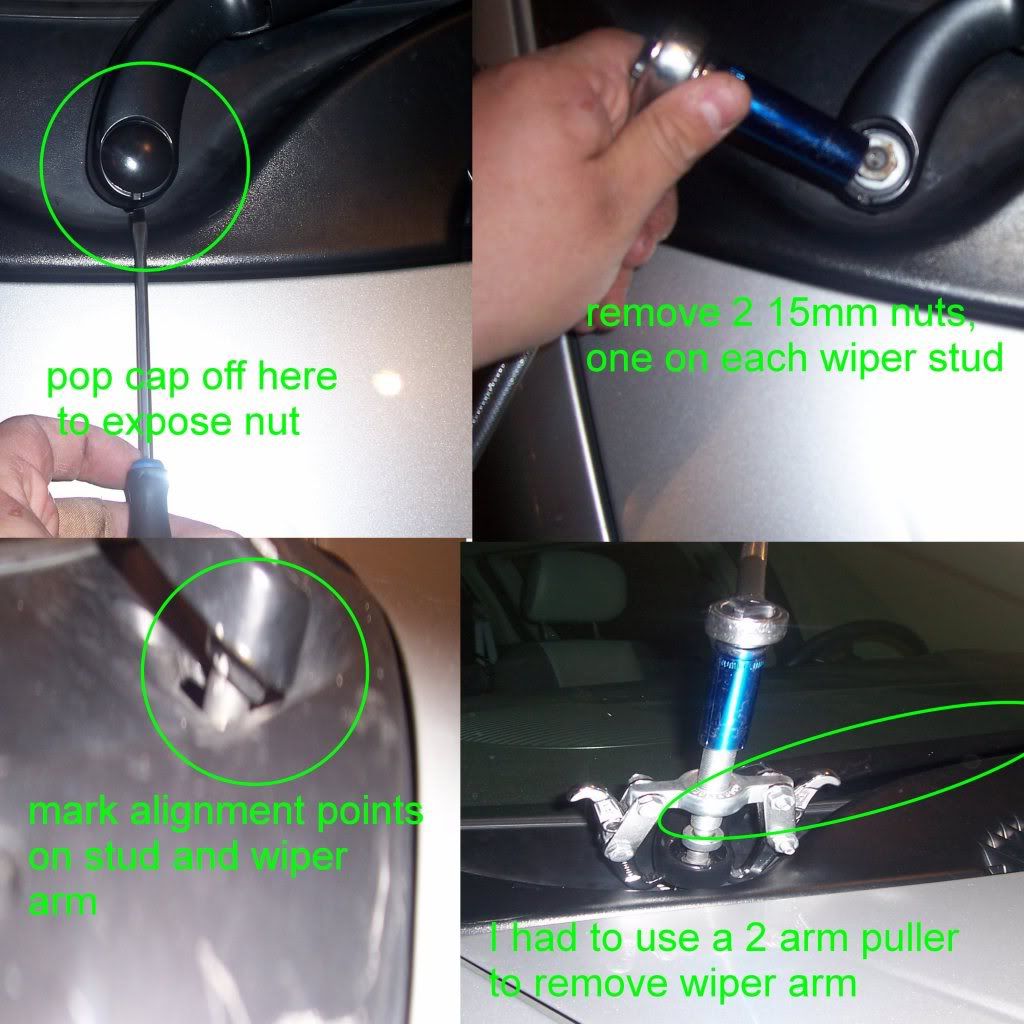
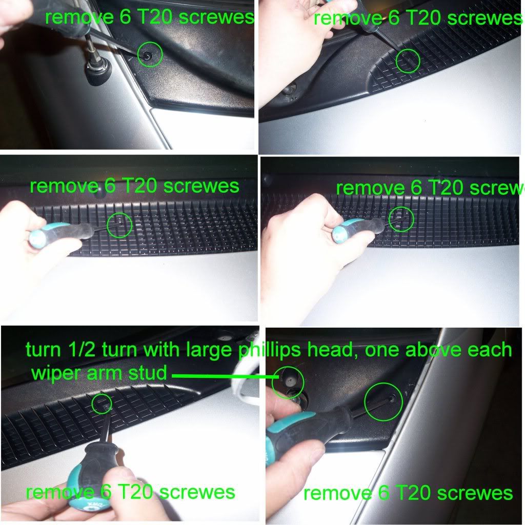
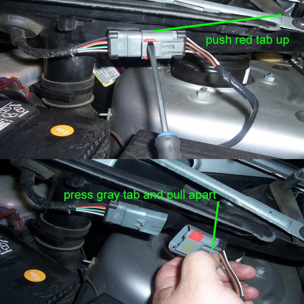
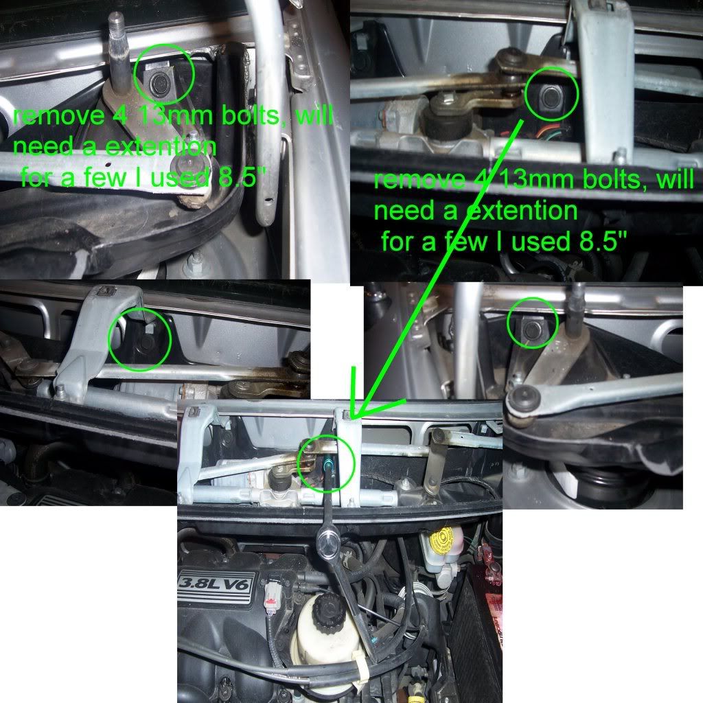
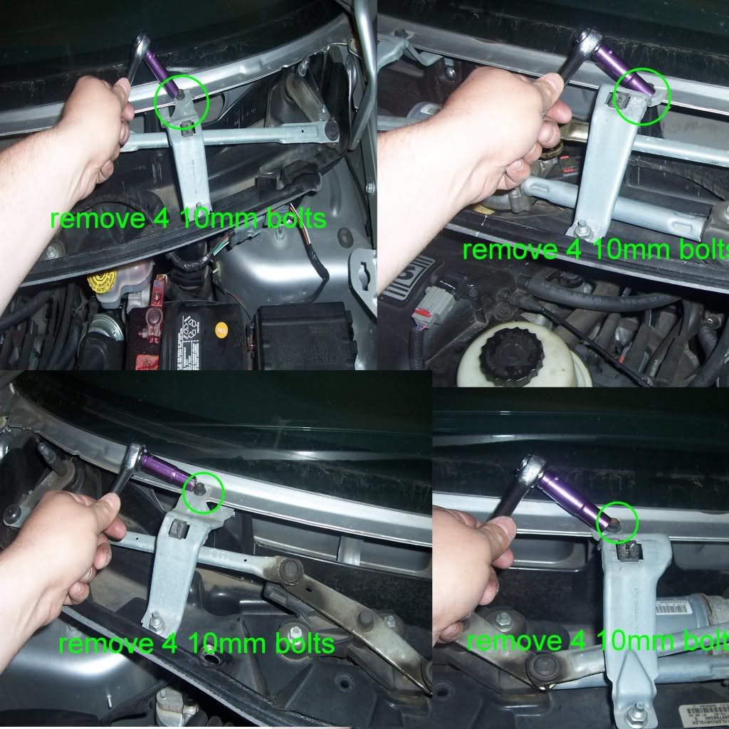
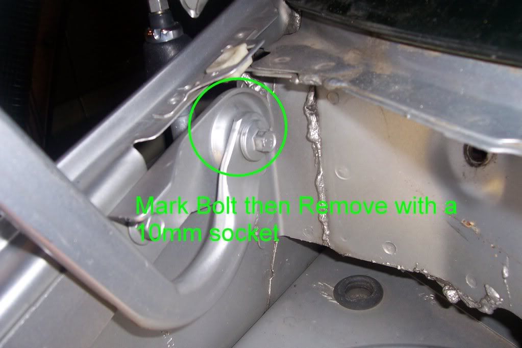
how to remove wiper crowl
this is on my 2006 DGC, takes about 15mins to take off, gives alot more room on the back side if needed
15mm socket
13mm socket
10mm socket
small screw driver
2-arm puller (got mine from Harbor Freight 3pc set, smallest size in the set is what I used)
8" or larger extention
T-20 screw driver

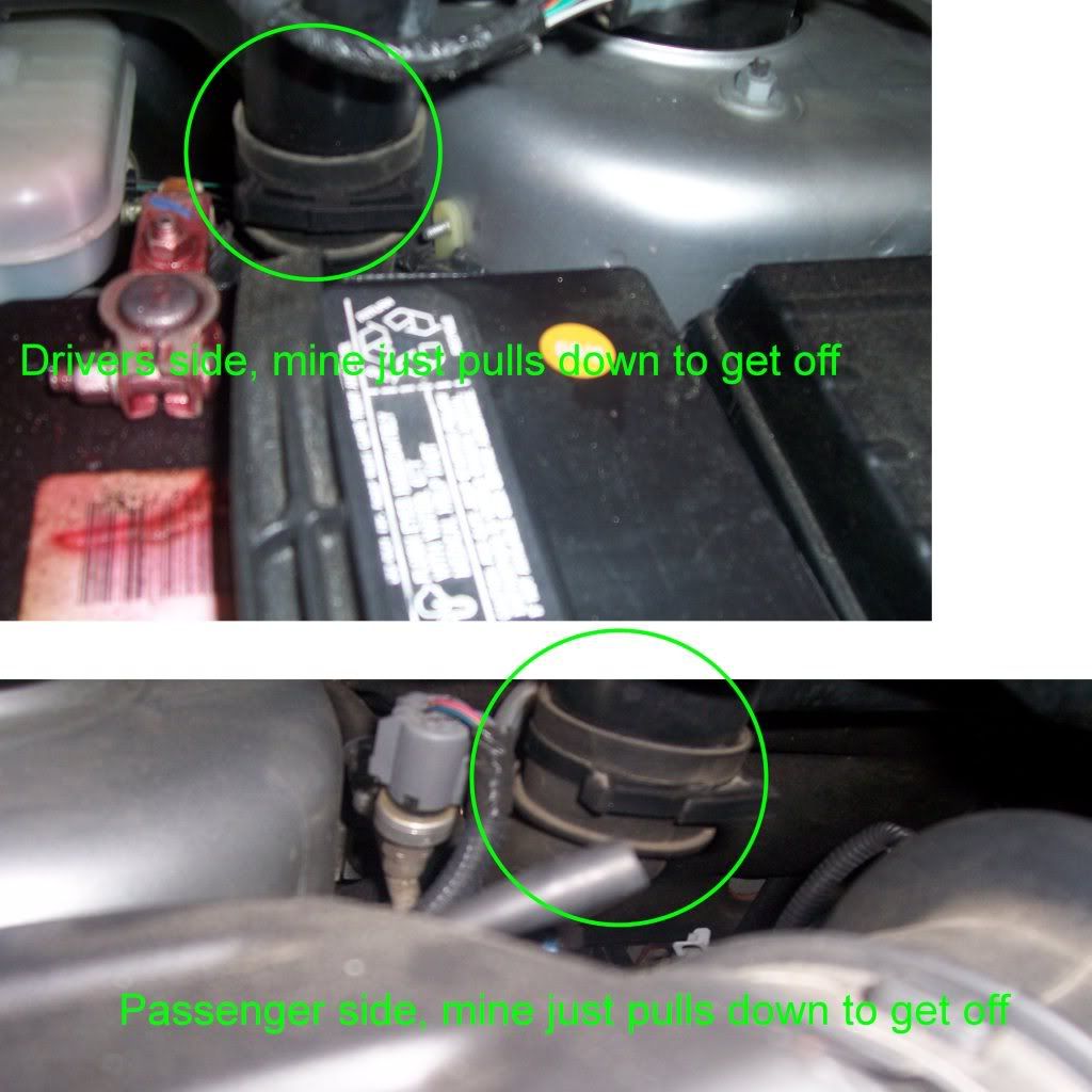
if you want to remove the hood for even more room
Notice how much more room there is
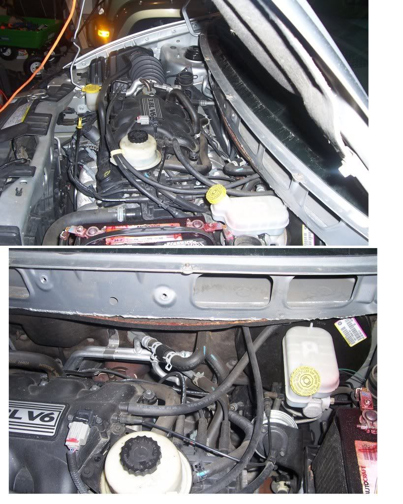
this is on my 2006 DGC, takes about 15mins to take off, gives alot more room on the back side if needed
15mm socket
13mm socket
10mm socket
small screw driver
2-arm puller (got mine from Harbor Freight 3pc set, smallest size in the set is what I used)
8" or larger extention
T-20 screw driver
if you want to remove the hood for even more room
Notice how much more room there is
Thanks So Much for these, It made changing the plugs on my wife's minivan ALOT easier
Again Thanks
CYLINDER HEAD
REMOVAL
Drain cooling system. Refer to COOLING SYSTEM for procedure.
Disconnect negative cable from battery.
Remove upper and lower intake manifolds. Refer to procedure in this section
WARNING: INTAKE MANIFOLD GASKET IS MADE OF VERY THIN METAL AND MAY CAUSE PERSONAL INJURY, HANDLE WITH CARE.
Disconnect coil wires, sending unit wire, heater hoses and bypass hose.
Remove PCV system hoses, evaporation control system hose and cylinder head covers.
Remove exhaust manifolds. Refer to procedure in this section.
Remove rocker arm and shaft assemblies. Remove push rods and mark positions to ensure installation in original locations.
Remove the nine head bolts from each cylinder head and remove cylinder heads Cylinder Head Bolts Location and Tightening Sequence
INSTALLATION
Clean all sealing surfaces of cylinder block and cylinder heads.
Install new gaskets on cylinder block Head Gasket Installation
The cylinder head bolts are torqued using the torque yield method, they should be examined BEFORE reuse. If the threads are necked down, the bolts should be replaced Checking Bolts for Stretching (Necking)
Necking can be checked by holding a scale or straight edge against the threads. If all the threads do not contact the scale the bolt should be replaced.
Tighten the cylinder head bolts 1 - 8 in the sequence shown in Cylinder Head Bolts Location and Tightening Sequence Using the 4 step torque turn method, tighten according to the following values:
Step 1: Bolts 1 - 8 to 61 N�m (45 ft. lbs.)
Step 2: Bolts 1 - 8 to 88 N�m (65 ft. lbs.)
Step 3: Bolts 1 - 8 (again) to 88 N�m (65 ft. lbs.)
Step 4: Bolts 1 - 8 turn an additional 1/4 Turn. (Do not use a torque wrench for this step.)
NOTE: Bolt torque after 1/4 turn should be over 122 N�m (90 ft. lbs.) If not, replace the bolt.
Tighten head bolt number 9 Cylinder Head Bolts Location and Tightening Sequence to 33 N�m (25 ft. lbs.) after head bolts 1 - 8 have been tighten to specifications.
Inspect push rods and replace worn or bent rods.
Install push rods, rocker arm and shaft assemblies with the stamped steel retainers in the four positions, tighten to 28 N�m (250 in. lbs.) Rocker Arm Shaft Retainers
Place new cylinder head cover gaskets in position and install cylinder head covers. Tighten to 12 N�m (105 in. lbs.)
Install exhaust manifolds and tighten bolts to 27 N�m (20 ft. lbs.) and nuts to 20 N�m (15 ft. lbs.)
Install upper and lower intake manifolds. Refer to procedure in this section.
Connect ignition cables, ignition coil connector, and sending unit connector.
Connect heater and coolant by-pass hose.
Fill cooling system. Refer to COOLING SYSTEM for procedure.
Connect negative cable to battery.
This is for the 1996 to 2000 NS mini vans with a 3.3 and 3.8 engines. TORQUE
DESCRIPTION N�m Ft. Lbs. In. Lbs.
Camshaft Sprocket - Bolt 54 40 -
Camshaft Thrust Plate - Bolts 12 - 105
Connecting Rod Cap - Bolts 54 + � turn 40 + � turn -
Crankshaft Main Bearing Cap - Bolts 41 + � turn 30 + � turn -
Crankshaft Oil Seal Retainer Rear - Bolts 12 - 105
Crankshaft Damper - Bolt 54 40 -
Cylinder Head - Bolts Refer to Procedure
Cylinder Head Cover - Bolts 12 - 105
Drive Plate to Crankshaft 95 70 -
Engine Mounting Refer to Procedure
Exhaust Manifold - Bolts 23 - 200
Exhaust Crossover Pipe - Bolts 33 25 -
Intake Manifold Lower - Bolts 23 - 200
Intake Manifold Gasket Retainer - Bolts 12 - 105
Intake Manifold Upper - Bolts 28 - 250
Oil Filter Attaching Nipple 41 30 -
Oil Filter 14 10 -
Oil Pan - Bolts 12 - 105
Oil Pan Drain - Plug 27 20 -
Oil Pump Cover Plate - Bolts 12 - 105
Oil Pump Pick-up Tube - Bolt 28 - 250
Oil Dipstick Housing - Bolt 48 35 -
Rocker Arm Shaft - Bolts 28 - 250
Spark Plug 27 20 -
Tappet Retainer Yoke - Bolts 12 - 105
Timing Chain Case Cover - - -
- M8 Bolt 27 20 -
- M10 Bolt 54 40 -
Water Pump - Bolts 12 - 105
Engine Oil Change Indicator System — If Equipped
Oil Change Required
Your vehicle is equipped with an engine oil change indicator system. The “Oil Change Required” message will flash in the EVIC display for approximately five seconds after a single chime has sounded, to indicate the next scheduled oil change interval. The engine oil change indicator system is duty-cycle based, which means the engine oil change interval may fluctuate dependent upon your personal driving style.
Unless reset, this message will continue to display each time you turn the ignition switch to the ON/RUN position. To turn off the message temporarily, press and release the Trip Odometer button on the instrument cluster. To reset the oil change indicator system (after performing the scheduled maintenance) refer to the following procedure.
Turn the ignition switch to the ON position. Do not start the engine.
Fully depress the accelerator pedal, slowly, three times within 10 seconds.
Turn the ignition switch to the OFF/LOCK position.
Note: If the indicator message illuminates when you start the vehicle, the oil change indicator system did not reset. If necessary repeat this procedure.