

DIY Installing an aftermarket air intake

This is my first DIY write up so be gentle 
Tools needed:
For removal of stock intake assembly:
Flat head screw driver
socket and/or pliers
For installation of new air intake (in addition to above):
Drill (for making your own mounting brackets)
Pliers for grasping and bending the metal brackets
Saw (I used a rotary tool, but a hacksaw will work fine to cut the metal for your brackets. In a real pinch, use your drill to drill multiple holes in a line across where you want your cut and then just bend and snap it off)
And Zip ties lol
Before I had my mounting solution figured out, I just had my intake held in there by zip ties for a couple of days.
Optional tools:
Rotary tool (dremel, etc) it makes some of the sanding easier.
Drill with a wire brush attachment (for stripping paint and rust off)
Acetone (to wipe the brackets down with before you paint them)
Total cost:
intake off of ebay $30 with free shipping
2 PCV (power crankcase 90* elbows) $5 (from advance auto parts)
Metal steel strip for brackets $4 (from home depot)
= $39 grand total
I think all of you will agree that this turned out great especially in comparison to name brand intakes. If you are really a stickler, you can always go and buy a k&n filter separately and use it.
If you're unsure which individual intake tubing pieces you need (if you're trying to piece one together from the intake aisle at advance auto parts), you can either get ideas from ebay ads or just buy the kit from ebay like I did. I didn't feel like working it out by trial and error. The $30 price tag was well worth it.
These steps and concepts can be applied to all air intakes. People who get a kit from a big name such as K&N or one of the others don't have to worry about mounting issues, but people who don't want to shell out the money just need a bit of imagination to figure these things out for themselves (and can get intake kits from ebay for $30'ish).
I am going to provide step by step instructions including removal of the stock intake assembly. I realize a lot of us on here can figure this out on our own, but I wanted to include it for anyone surfing the web or just for new guys who aren't quite sure how to go about it. When things get demystified, confidence levels rise. When confidence levels rise, we achieve more.
First things first: take your flat head screwdriver and loosen any and all clamps that you see on your intake.
Photo0354.jpg
Most likely you will have the two seen above and one more where the black plastic assembly connects to the throttle body.
The goal here is to just look for anything and everything that is holding the air intake assembly together.
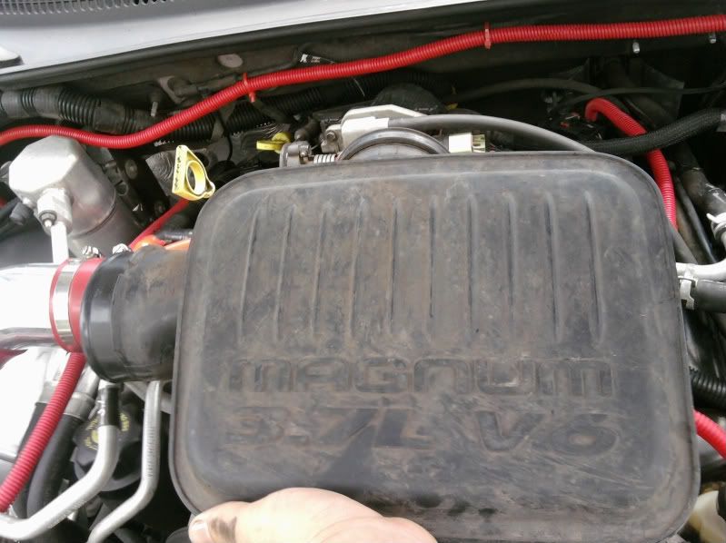
Next we are going to remove the air filter housing lid. Start by unsnapping the clips on the side
Photo0357.jpg
Then pull the breather hose off of the fitting
Photo0359.jpg
Go ahead and unplug the black breather hose from the other end where it connects. This hose will typically be replaced with a silicone hose that will come with your kit (even ebay kits). The other end goes where this red hose is at.
Photo0371.jpg
The black breather hose we just removed isn't in either of the 2 previous images, but is just runs from the nipple in the former to the "T" in the latter where the red one is just above.
Now there is nothing else holding the air filter housing lid in there. Just slide it a bit and it'll lift right out. Go ahead and pull it from the accordion tubing that you already loosened the clamp on earlier.
The accordion tubing can now be pulled right off of the assembly right next to the throttle body in the same fashion.
Before removing this assembly at the throttle body, it is important to pull out the IAT (Intake Air Temperature) sensor. You can choose to unplug it at this step if you want to get a better look at it and also to make sure it gets put aside without being damaged. Special note about removing these sensors and any other sensors or plugs: Always grasp it by the plastic plug/fitting, NEVER pull on the wires. Just press on the lever and pull.
Photo0364.jpg
This is what the sensor looks like. I didn't get a picture of it on the stock intake, but this is the same setup. Just ease it out of the rubber grommet.
The plug and sensor come apart like so
Photo0365.jpg
With the sensor pulled out, there is nothing else keeping you from removing it from the throttle body. If you haven't already, loosen this clamp all of the way and slide the assembly off of the throttle body and set it aside.
Now the only piece remaining of the stock intake assembly is the lower portion of the air filter housing which includes the 90* snorkel that runs to the fender.
I'm pretty sure there were only 3 fasteners holding it in place. 1 nut/washer holding it in place all the way at the passenger fender
Photo0323.jpg
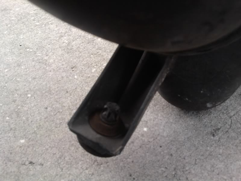
The other two fasteners are plastic dealies that screw over bolt studs fixed to the metal wheel well
Photo0320.jpg
This is what they look like when screwed on.
One is on the inside of the lower air filter housing
Photo0358.jpg
The other is on the side of the assembly
Keep in mind where these mounting points are in the vehicle. We are going to be using two of them for mounting our aftermarket intake.
Now you have the factory air intake assembly out. Isn't it already looking so much cleaner in there? It really does make a huge difference for un-cluttering the engine bay.
Not required, but feel free to clean things at this point while they are much easier to get to with the intake removed.
Once you get your new intake all put together and in there, it almost never positions itself just right the first time. Therefore, once you start putting pieces and clamps in, very lightly tighten the clamps just enough to hold the pieces together because we are going to do some wiggling to make it all line up right (We don't want the intake or filter vibrating all over something else in the engine bay).
Let's start at the throttle body. At this point go ahead and insert the rubber IAT sensor grommet in the tubing (there will be a hole where it goes somewhere near the throttle body).
Photo0362.jpg
Attach the first piece (it should be obvious from pictures which piece this is) with a coupler and TWO clamps (one for each end of the coupler). With the clamps on the coupler, slide it over both the throttle body and the first piece of intake tubing and go ahead and lightly tighten those clamps
Photo0361.jpg
Go ahead and gently insert the IAT sensor into the grommet and ease it all the way in there.
Photo0363.jpg
Next, go ahead and attach the next piece of tubing in the same way in the position seen here
Photo0372.jpg
Go ahead and lightly tighten those clamps
This is where it can go 2 ways based on your kit. This is the final piece of most kits and it will leave the end setup looking like this
Photo0324.jpg
If this is your setup and you are happy with it, then you will only be using the one mounting point. This works fine, but I chose to get the filter further from the exhaust manifolds and closer to the headlight.
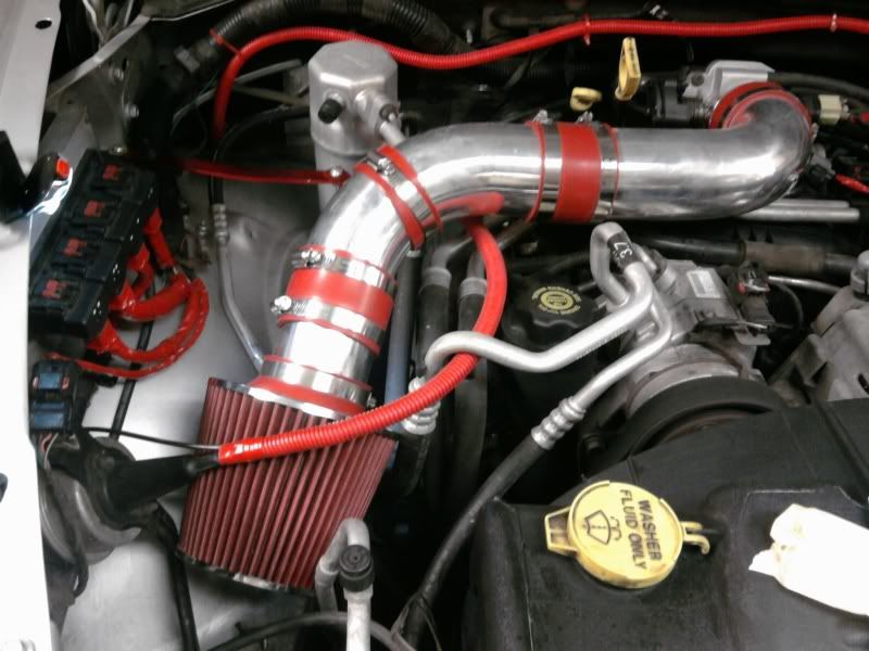
If you choose the same thing, your end result will look like this
With this option, you will need another coupler and 2 clamps and a 4" piece of the intake tubing (factor this into your cost<-- maybe another $15 if that. I got it for free from the ebay seller for writing up these installation instructions). You can get these additional pieces either from your parts store or from the ebay seller you bought the kit from. A competent and quality seller should have no problem setting up this custom order for you.
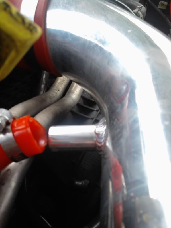
We are going to attach the first mounting point now. slide a coupler and a clamp over the curved portion approximately in the position seen in the previous two pictures (in the 1st of the two, it is where the black coupler and clamp are. The same ebay seller sent me an extra coupler to replace the black one). Once you determine how much of the coupler you will be using you can go ahead and trim off the rest. In the previous photo I had not done this yet. This clamp and coupler are going to be holding a bent strip of aluminum that the seller will provide you with in the kit (or you will have to get separately from home depot). Aluminum is suggested for this piece because of the need to manipulate it and bend it.
Photo0373.jpg
The steel strip needs to be approximately 10" long. It will need one hole drilled in it at the point seen in the picture above. It will then need 2 holes drilled in it where it will be attached to the black bracket mounting point.
Photo0376.jpg
Notice we are using the same stud and nut/washer that was used on the stock intake. There was already a 2nd hole in the black bracket so I just put a bolt and washer/nut in the 2nd hole. If you don't already have this 2nd hole in the black bracket, go ahead and drill one in there. It is important for the steel strip not to rotate around at this point. Just pay attention to the direction your holes are pointing. We are fortunate because this hole and stud point directly in the direction that we need the steel strip to go to reach the intake.
I put a slight bend in the steel strip to help encourage the intake to have some lift to it to increase clearance. Use your judgment and eyes here. The point is to just get it into a position where the intake isn't rubbing/vibrating on anything.
Go ahead and slip a bolt and nut through the hole joining the little twisted "L" piece and the steel strip to hold them together as seen 2 pictures above.
Now we are going to attach the breather hose to the 2nd intake piece. You will be using the provided silicone hose that came with your ebay kit or some hosing from the part store.
This is where I ran into an obstacle because the path that the hose has to travel is "S" shaped and it causes the hose to kink
Photo0312-1.jpg
I fixed this by utilizing the black 90* PCV elbows seen in the picture above. You will need to trim the hose into the needed lengths, but you can just eyeball the lengths. It doesn't have to be exact because the hose has flex to it.
These PCV elbows can be found at advance auto parts. I have suggested improvements to help get around this problem to the ebay seller (as part of my bartering). After they consider the cost of them, they may or may not choose to provide options to eliminate this issue. Mostly likely, the kit you get will be like mine.
Photo0330.jpg
Photo0332.jpg
You can either attach the silicone breather hose to the elbows with clamps or zip ties. The hose was a really snug fit on the elbows and the "T" so I just used matching zip ties. I chose a clamp for the connection to the fitting on the intake so that I can take it on and off as needed.
Now you can insert the 3rd and final optional 4" length intake piece (discussed above). Or you can attach this 4" piece to the filter first as seen below. Attach it with a coupler in the way as all of these. The lower of these two clamps is the one that we are going to use to hold the 2nd and final mounting bracket. This mounting bracket is going to be secured to one of the studs on the fender.
Photo0394.jpg
Because my strip of aluminum wasn't long enough, I cut it and extended it with some of my steel strip. The bent pieces in the vertical bracket in the picture above are aluminum while the straight piece is steel. They are attached with bolts and washer/nuts.
Here are some close ups of my bottom bracket so you can get an idea of the shape
Photo0388.jpg
Photo0387.jpg
Photo0321.jpg
This is the type of stud you'll be mounting to. The one you'll be using is actually on the wheel well hump.
Use pliers and to bend the aluminum into the shape you are looking for. One 90* lip will be at the bottom. Drill a hole in that lip so that it can slide over the stud seen above. Then use the plastic fastener that was already used there with the stock intake to hold the bracket to the stud.
The other bent lip of the bracket (approx. 120* maybe) is going to slide between the clamp and the coupler.
Now you can attach your filter.
Now that you have everything in place it is time to work on fitment. You will have already been working and improving upon this as you were attaching all of the mounting points, but this is the last check before we tighten everything up. The idea is to utilize the slack that the couplers allow us to take advantage of and to make minor adjustments with this slack. Once you find the positioning that you want for each piece, tighten its respective clamps down to hold them still.
Now you are done with the functional installation of your intake! Woohoo!
You should have something that looks like either:
This
Photo0324.jpg
Or this
You could have saved the mounting for another day and just used zipties for the time being, but don't rely on this for permanent solutions.
I got the sanding and painting done on the brackets. It can be seen in the pictures. The color choice here is up to you. I personally went with a base coat of chrome with a good coat of metallic red over that with some clear gloss over that. The paint job is a bit rough right now, but I may make it better in the future.
Here is my industrial paint booth
Photo0385.jpg
You can either sell your stock intake on ebay or craigslist or here on the forum. Or you can hold onto it for if you ever sell your truck, the buyer or you may want to put it back to stock first. That is the beauty of this- you have the flexibility to put it all back the way you want.
Guys, please feel free to make suggestions if you feel there is anything missing. Maybe this will make it into the DIY thread? I will make revisions as necessary. If more pictures are needed, I have more and I can always take more.
Tools needed:
For removal of stock intake assembly:
Flat head screw driver
socket and/or pliers
For installation of new air intake (in addition to above):
Drill (for making your own mounting brackets)
Pliers for grasping and bending the metal brackets
Saw (I used a rotary tool, but a hacksaw will work fine to cut the metal for your brackets. In a real pinch, use your drill to drill multiple holes in a line across where you want your cut and then just bend and snap it off)
And Zip ties lol
Before I had my mounting solution figured out, I just had my intake held in there by zip ties for a couple of days.
Optional tools:
Rotary tool (dremel, etc) it makes some of the sanding easier.
Drill with a wire brush attachment (for stripping paint and rust off)
Acetone (to wipe the brackets down with before you paint them)
Total cost:
intake off of ebay $30 with free shipping
2 PCV (power crankcase 90* elbows) $5 (from advance auto parts)
Metal steel strip for brackets $4 (from home depot)
= $39 grand total
I think all of you will agree that this turned out great especially in comparison to name brand intakes. If you are really a stickler, you can always go and buy a k&n filter separately and use it.
If you're unsure which individual intake tubing pieces you need (if you're trying to piece one together from the intake aisle at advance auto parts), you can either get ideas from ebay ads or just buy the kit from ebay like I did. I didn't feel like working it out by trial and error. The $30 price tag was well worth it.
These steps and concepts can be applied to all air intakes. People who get a kit from a big name such as K&N or one of the others don't have to worry about mounting issues, but people who don't want to shell out the money just need a bit of imagination to figure these things out for themselves (and can get intake kits from ebay for $30'ish).
I am going to provide step by step instructions including removal of the stock intake assembly. I realize a lot of us on here can figure this out on our own, but I wanted to include it for anyone surfing the web or just for new guys who aren't quite sure how to go about it. When things get demystified, confidence levels rise. When confidence levels rise, we achieve more.
First things first: take your flat head screwdriver and loosen any and all clamps that you see on your intake.
Photo0354.jpg
Most likely you will have the two seen above and one more where the black plastic assembly connects to the throttle body.
The goal here is to just look for anything and everything that is holding the air intake assembly together.
Next we are going to remove the air filter housing lid. Start by unsnapping the clips on the side
Photo0357.jpg
Then pull the breather hose off of the fitting
Photo0359.jpg
Go ahead and unplug the black breather hose from the other end where it connects. This hose will typically be replaced with a silicone hose that will come with your kit (even ebay kits). The other end goes where this red hose is at.
Photo0371.jpg
The black breather hose we just removed isn't in either of the 2 previous images, but is just runs from the nipple in the former to the "T" in the latter where the red one is just above.
Now there is nothing else holding the air filter housing lid in there. Just slide it a bit and it'll lift right out. Go ahead and pull it from the accordion tubing that you already loosened the clamp on earlier.
The accordion tubing can now be pulled right off of the assembly right next to the throttle body in the same fashion.
Before removing this assembly at the throttle body, it is important to pull out the IAT (Intake Air Temperature) sensor. You can choose to unplug it at this step if you want to get a better look at it and also to make sure it gets put aside without being damaged. Special note about removing these sensors and any other sensors or plugs: Always grasp it by the plastic plug/fitting, NEVER pull on the wires. Just press on the lever and pull.
Photo0364.jpg
This is what the sensor looks like. I didn't get a picture of it on the stock intake, but this is the same setup. Just ease it out of the rubber grommet.
The plug and sensor come apart like so
Photo0365.jpg
With the sensor pulled out, there is nothing else keeping you from removing it from the throttle body. If you haven't already, loosen this clamp all of the way and slide the assembly off of the throttle body and set it aside.
Now the only piece remaining of the stock intake assembly is the lower portion of the air filter housing which includes the 90* snorkel that runs to the fender.
I'm pretty sure there were only 3 fasteners holding it in place. 1 nut/washer holding it in place all the way at the passenger fender
Photo0323.jpg
The other two fasteners are plastic dealies that screw over bolt studs fixed to the metal wheel well
Photo0320.jpg
This is what they look like when screwed on.
One is on the inside of the lower air filter housing
Photo0358.jpg
The other is on the side of the assembly
Keep in mind where these mounting points are in the vehicle. We are going to be using two of them for mounting our aftermarket intake.
Now you have the factory air intake assembly out. Isn't it already looking so much cleaner in there? It really does make a huge difference for un-cluttering the engine bay.
Not required, but feel free to clean things at this point while they are much easier to get to with the intake removed.
Once you get your new intake all put together and in there, it almost never positions itself just right the first time. Therefore, once you start putting pieces and clamps in, very lightly tighten the clamps just enough to hold the pieces together because we are going to do some wiggling to make it all line up right (We don't want the intake or filter vibrating all over something else in the engine bay).
Let's start at the throttle body. At this point go ahead and insert the rubber IAT sensor grommet in the tubing (there will be a hole where it goes somewhere near the throttle body).
Photo0362.jpg
Attach the first piece (it should be obvious from pictures which piece this is) with a coupler and TWO clamps (one for each end of the coupler). With the clamps on the coupler, slide it over both the throttle body and the first piece of intake tubing and go ahead and lightly tighten those clamps
Photo0361.jpg
Go ahead and gently insert the IAT sensor into the grommet and ease it all the way in there.
Photo0363.jpg
Next, go ahead and attach the next piece of tubing in the same way in the position seen here
Photo0372.jpg
Go ahead and lightly tighten those clamps
This is where it can go 2 ways based on your kit. This is the final piece of most kits and it will leave the end setup looking like this
Photo0324.jpg
If this is your setup and you are happy with it, then you will only be using the one mounting point. This works fine, but I chose to get the filter further from the exhaust manifolds and closer to the headlight.
If you choose the same thing, your end result will look like this
With this option, you will need another coupler and 2 clamps and a 4" piece of the intake tubing (factor this into your cost<-- maybe another $15 if that. I got it for free from the ebay seller for writing up these installation instructions). You can get these additional pieces either from your parts store or from the ebay seller you bought the kit from. A competent and quality seller should have no problem setting up this custom order for you.
We are going to attach the first mounting point now. slide a coupler and a clamp over the curved portion approximately in the position seen in the previous two pictures (in the 1st of the two, it is where the black coupler and clamp are. The same ebay seller sent me an extra coupler to replace the black one). Once you determine how much of the coupler you will be using you can go ahead and trim off the rest. In the previous photo I had not done this yet. This clamp and coupler are going to be holding a bent strip of aluminum that the seller will provide you with in the kit (or you will have to get separately from home depot). Aluminum is suggested for this piece because of the need to manipulate it and bend it.
Photo0373.jpg
The steel strip needs to be approximately 10" long. It will need one hole drilled in it at the point seen in the picture above. It will then need 2 holes drilled in it where it will be attached to the black bracket mounting point.
Photo0376.jpg
Notice we are using the same stud and nut/washer that was used on the stock intake. There was already a 2nd hole in the black bracket so I just put a bolt and washer/nut in the 2nd hole. If you don't already have this 2nd hole in the black bracket, go ahead and drill one in there. It is important for the steel strip not to rotate around at this point. Just pay attention to the direction your holes are pointing. We are fortunate because this hole and stud point directly in the direction that we need the steel strip to go to reach the intake.
I put a slight bend in the steel strip to help encourage the intake to have some lift to it to increase clearance. Use your judgment and eyes here. The point is to just get it into a position where the intake isn't rubbing/vibrating on anything.
Go ahead and slip a bolt and nut through the hole joining the little twisted "L" piece and the steel strip to hold them together as seen 2 pictures above.
Now we are going to attach the breather hose to the 2nd intake piece. You will be using the provided silicone hose that came with your ebay kit or some hosing from the part store.
This is where I ran into an obstacle because the path that the hose has to travel is "S" shaped and it causes the hose to kink
Photo0312-1.jpg
I fixed this by utilizing the black 90* PCV elbows seen in the picture above. You will need to trim the hose into the needed lengths, but you can just eyeball the lengths. It doesn't have to be exact because the hose has flex to it.
These PCV elbows can be found at advance auto parts. I have suggested improvements to help get around this problem to the ebay seller (as part of my bartering). After they consider the cost of them, they may or may not choose to provide options to eliminate this issue. Mostly likely, the kit you get will be like mine.
Photo0330.jpg
Photo0332.jpg
You can either attach the silicone breather hose to the elbows with clamps or zip ties. The hose was a really snug fit on the elbows and the "T" so I just used matching zip ties. I chose a clamp for the connection to the fitting on the intake so that I can take it on and off as needed.
Now you can insert the 3rd and final optional 4" length intake piece (discussed above). Or you can attach this 4" piece to the filter first as seen below. Attach it with a coupler in the way as all of these. The lower of these two clamps is the one that we are going to use to hold the 2nd and final mounting bracket. This mounting bracket is going to be secured to one of the studs on the fender.
Photo0394.jpg
Because my strip of aluminum wasn't long enough, I cut it and extended it with some of my steel strip. The bent pieces in the vertical bracket in the picture above are aluminum while the straight piece is steel. They are attached with bolts and washer/nuts.
Here are some close ups of my bottom bracket so you can get an idea of the shape
Photo0388.jpg
Photo0387.jpg
Photo0321.jpg
This is the type of stud you'll be mounting to. The one you'll be using is actually on the wheel well hump.
Use pliers and to bend the aluminum into the shape you are looking for. One 90* lip will be at the bottom. Drill a hole in that lip so that it can slide over the stud seen above. Then use the plastic fastener that was already used there with the stock intake to hold the bracket to the stud.
The other bent lip of the bracket (approx. 120* maybe) is going to slide between the clamp and the coupler.
Now you can attach your filter.
Now that you have everything in place it is time to work on fitment. You will have already been working and improving upon this as you were attaching all of the mounting points, but this is the last check before we tighten everything up. The idea is to utilize the slack that the couplers allow us to take advantage of and to make minor adjustments with this slack. Once you find the positioning that you want for each piece, tighten its respective clamps down to hold them still.
Now you are done with the functional installation of your intake! Woohoo!
You should have something that looks like either:
This
Photo0324.jpg
Or this
You could have saved the mounting for another day and just used zipties for the time being, but don't rely on this for permanent solutions.
I got the sanding and painting done on the brackets. It can be seen in the pictures. The color choice here is up to you. I personally went with a base coat of chrome with a good coat of metallic red over that with some clear gloss over that. The paint job is a bit rough right now, but I may make it better in the future.
Here is my industrial paint booth
Photo0385.jpg
You can either sell your stock intake on ebay or craigslist or here on the forum. Or you can hold onto it for if you ever sell your truck, the buyer or you may want to put it back to stock first. That is the beauty of this- you have the flexibility to put it all back the way you want.
Guys, please feel free to make suggestions if you feel there is anything missing. Maybe this will make it into the DIY thread? I will make revisions as necessary. If more pictures are needed, I have more and I can always take more.
Last edited by Rantz; Sep 20, 2010 at 10:33 PM. Reason: Corrected name for the IAT sensor

Professional
Joined: Mar 2010
Posts: 228
Likes: 0
From: Okemos, MI
First, that looks pretty good. Especially for $40. I have a couple of comments related to the MAF that I have picked up from dealing with my Mustang...you might be able to gain a bit more out of it...
Clean that MAF. You have it apart anyhow, and that is the time to do it. First time I did that on the 'Stang, I swear I picked up like 20 hp. Not even kidding. You can buy MAF cleaner in an aerosol can at the parts store. Basically, over time your K&N filter (or whatever brand you have) oil will coat the wires inside the MAF and reduce its sensitivity. All you have to do is spray the heck out of it and let it dry...
Second, I am assuming your MAF is on the horizontal straight piece of tubing directly above the oil fill cap? If so, if it is possible, you might see a bit better throttle response by moving the MAF toward the filter iin front of any bends in the tubing. Like right where you have that band clamp that attaches the filter to the CAI. If you have the MAF in front of any bends in the tubing it will get a more consistent airflow across the elements inside of it, resulting in increased efficiency.
Just my two cents as to a couple of other things that cost next to nothing that may be worth a try if you are still in the experimenting mode.
Good job.
Currently the MAF is in the tubing immediately before the throttle body. I wiped and blew it off when I had it out. My current filter is a dry type, or at least that is what the seller told me. I will keep an eye on the cleanliness of the sensor. Thanks.
The wires are no where long enough for me to move it to the other end of the intake by the filter. Doesn't it give the computer a better indication of the air coming in by giving the reading right before it enters through the throttle body and into the intake manifold?
The wires are no where long enough for me to move it to the other end of the intake by the filter. Doesn't it give the computer a better indication of the air coming in by giving the reading right before it enters through the throttle body and into the intake manifold?
Professional
Joined: Mar 2010
Posts: 228
Likes: 0
From: Okemos, MI
Currently the MAF is in the tubing immediately before the throttle body. I wiped and blew it off when I had it out. My current filter is a dry type, or at least that is what the seller told me. I will keep an eye on the cleanliness of the sensor. Thanks.
The wires are no where long enough for me to move it to the other end of the intake by the filter. Doesn't it give the computer a better indication of the air coming in by giving the reading right before it enters through the throttle body and into the intake manifold?
The wires are no where long enough for me to move it to the other end of the intake by the filter. Doesn't it give the computer a better indication of the air coming in by giving the reading right before it enters through the throttle body and into the intake manifold?
I don't fully understand the reasoning, but I think it has something to do with the tubing messing with not the total flow of air but with the flow characteristics of the air as it passes through the MAF. That is, coming around the corner, some of the air is moving faster and some is moving slower, so it is possible that you are not getting a true indication of the overall flow through the tubing from the sample that is flowing over the elements in the MAF. Out at the filter, the flow through the MAF will be uniform.
If you can't do anything about it, then no biggie anyhow, right? I was just throwing it out there as a possibility that I know made a difference for me, albeit in a different car, that is pretty easy to try out.
Well I could extend the wires with some wiring if I really wanted to.
The thing is also that I am concerned that the MAFs reads are also influenced by the air. The air gets a bit warmed as it passes through the warm intake tubing. I figured that right before the air passes into the TB is the most honest place for the reading. If I am wrong with this, then I'd have no problem extending the wires and moving it towards the filter. I'd need to do a bit more homework before doing this though.
The thing is also that I am concerned that the MAFs reads are also influenced by the air. The air gets a bit warmed as it passes through the warm intake tubing. I figured that right before the air passes into the TB is the most honest place for the reading. If I am wrong with this, then I'd have no problem extending the wires and moving it towards the filter. I'd need to do a bit more homework before doing this though.

Captain
Joined: Dec 2009
Posts: 511
Likes: 0
From: California
Instead of re routing the PCV to the air intake you can buy these little filters from auto zone that you can put in the PCV tubing. They come in Red,Blue and Grey. They are only like 5 bucks and can save some time.
Mine passed smog with that and the intake, so it works fine!
Ill post up a picture once i get home today!
Mine passed smog with that and the intake, so it works fine!
Ill post up a picture once i get home today!
Trending Topics
It a pcv which is a positive crankcase vent tube which this is the air that is created when the engine is running and is just from all the stuff moving. I think auto makers did it this just so there wasnt a dead end tube in the engine bay. One on my jeep goes no where same goes for other friends vehicles
All I know is that it is called the breather hose. I just happened to use what were called PCV elbows because they happened to be the perfect size.
Now I am curious what exactly it is for. I will look into it...
Now I am curious what exactly it is for. I will look into it...