Starting the build process
#231
 12-24-2018, 09:23 PM


Bought the brake parts from O'Reilly. I'll pick them up on Friday, had to come from KC MO. Ball Joints will come from Rock Auto.
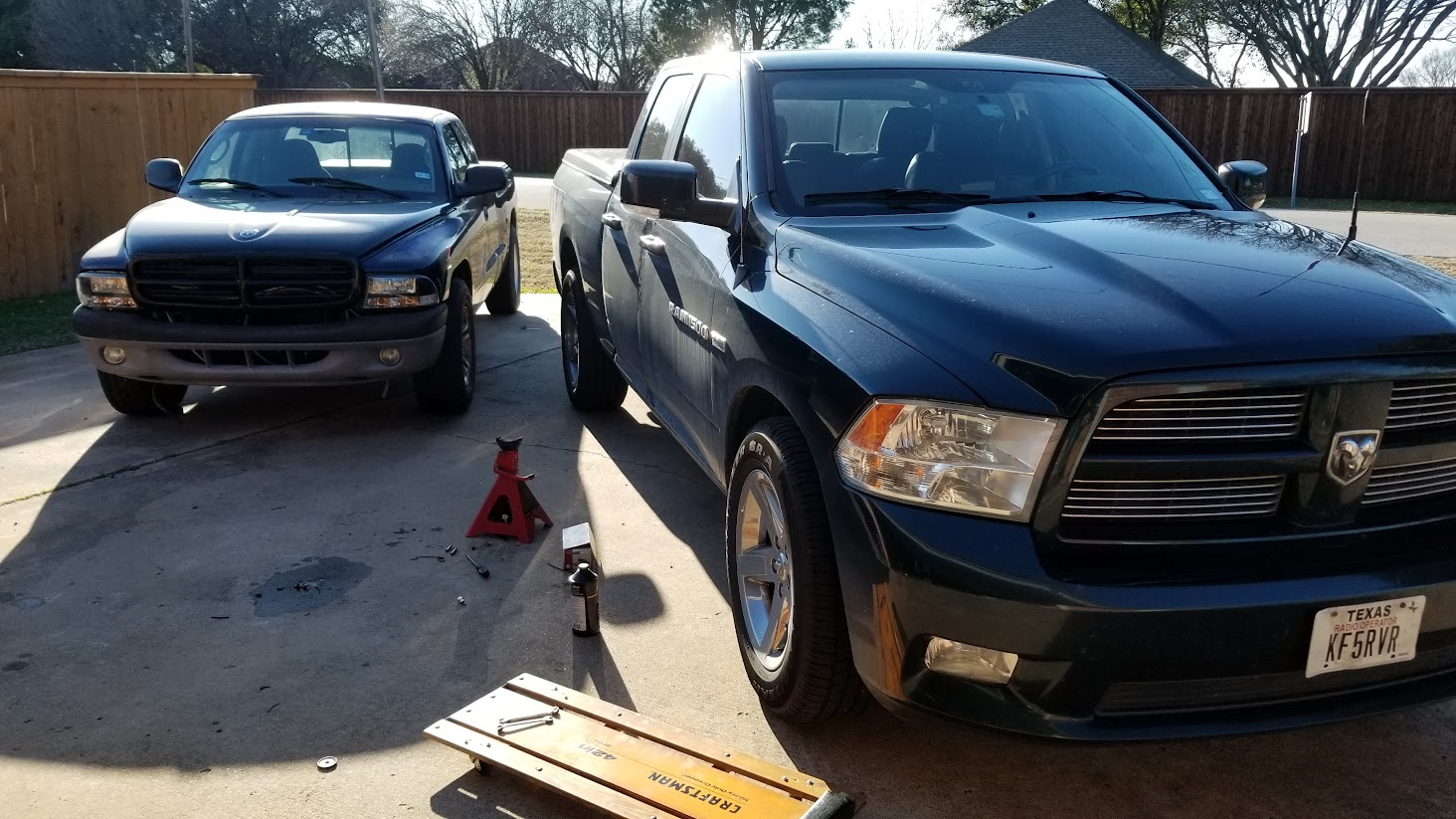
It's about to get nuts around here with both builds going simultaneously.
Dragster has the new wing, and we put the rear axle back in after getting the housing powdercoated, also put new axle shafts in. Short block is together, next step is valvetrain.
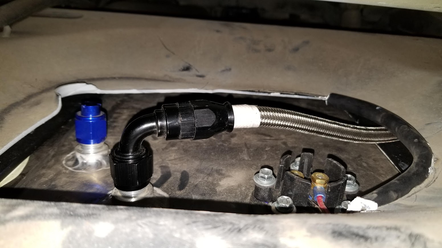
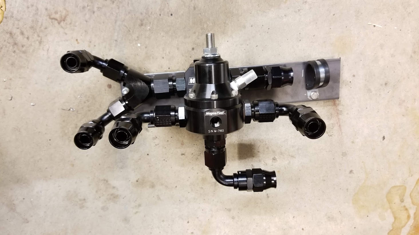
My last box from Magnafuel came today, so I can start piecing together the engine side of the fuel system. Fuel tank straps are painted, snubbers are glued on (Marine glue is NICE!), tank is ready to get hung back in the truck. I have the fuel lines ran semi-temporarily up to the engine bay, they'll need to be re-routed later, but I wanted to get the length figured out now. The pressure/supply runs up the driver side frame rail, curves around the brake booster and HVAC accumulator, and comes out on the passenger side. The return hose runs up the passenger frame rail and pops out behind the HVAC accumulator.


It's about to get nuts around here with both builds going simultaneously.
Dragster has the new wing, and we put the rear axle back in after getting the housing powdercoated, also put new axle shafts in. Short block is together, next step is valvetrain.
My last box from Magnafuel came today, so I can start piecing together the engine side of the fuel system. Fuel tank straps are painted, snubbers are glued on (Marine glue is NICE!), tank is ready to get hung back in the truck. I have the fuel lines ran semi-temporarily up to the engine bay, they'll need to be re-routed later, but I wanted to get the length figured out now. The pressure/supply runs up the driver side frame rail, curves around the brake booster and HVAC accumulator, and comes out on the passenger side. The return hose runs up the passenger frame rail and pops out behind the HVAC accumulator.
#232
12-26-2018, 06:02 PM


#233
12-27-2018, 10:47 PM
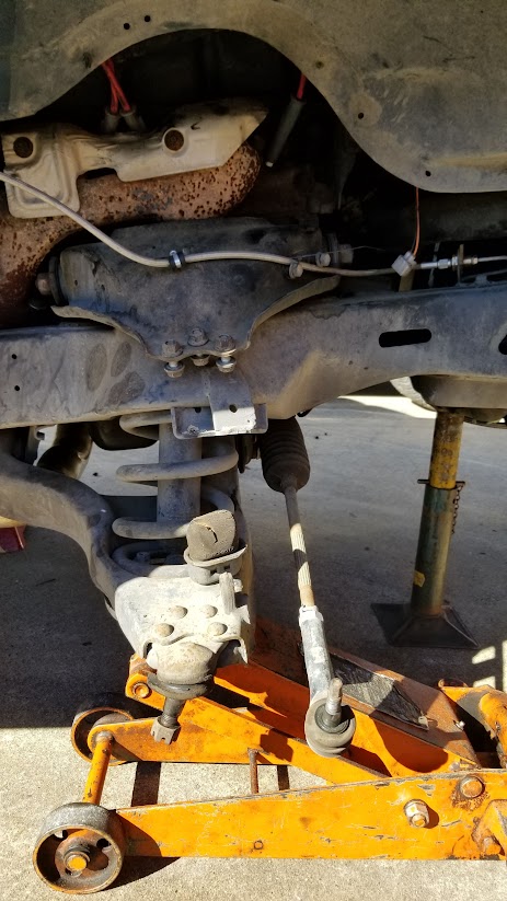
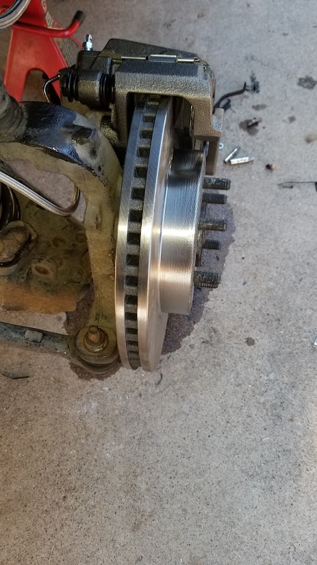
I got one side of the truck almost done today. Took the old brake stuff off, removed the hub/bearing assembly that was known good, removed the spindle, removed the shock, compressed the stock spring, pulled it out, compressed the new spring, stabbed it in, put the new spindle on, put my known good hub/bearing on, put the shock back on.
It wasn't anything REMOTELY easy done as said, but I got one side done today.
Tomorrow will be the other side.
Also got the second head on the dragster engine today.


It wasn't anything REMOTELY easy done as said, but I got one side done today.
Tomorrow will be the other side.
Also got the second head on the dragster engine today.
#234
12-28-2018, 01:02 AM
As I seek further information for the fuel cell wiring that is to be coming, I have found the following:
Fuel Pump Power: 16 AWG, Dark Green / Black
Fuel Pump Ground: 16 AWG, Black (attached to Splice 306)
Fuel Level Voltage: 18 AWG, Dark Blue / White
Fuel Level Ground: 18 AWG, Black / Light Blue (Attached to JC3, Splice 103, Splice 101)
Splice 101: Shared by all throttle body sensors and O2S 1/1
Splice 103: Shared by all O2S and Engine Vital Sensors
JC3:
Splice 306: Shared by all taillamps (all solid black wiring)
I plan to ground the fuel pump to the frame, so maintaining Splice 306 can be disregarded.
It looks like I will have to use the fuel sending unit leads though, not that I expected otherwise, but it looks like they are tied together to prevent a ground loop.
I will have to pick up the fuel pump supply wire, run it to a new relay, and that relay will supply power to the fuel pump. I do not trust the factory 16 gauge wire to feed a 20 amp fuel pump - calculator says it will be a 2.5 volt loss in the wire itself (no bueno). I don't exactly have room to be adding another barrier strip and relay in the rear compartment, but I'll find a space. It's only 1 wire in and out of the grommet, plus a local ground and local power.
Page 8W-30-4 (697) of the FSM indicates that on the fuel pump module, pin 1 is ground, pin 2 is sending unit ground (PCM C1P4), pin 3 is "Fuel Pump Relay Control" (PCM C3P26), and pin 4 is fuel pump power.
Page 8W-80-40 (925) of the FSM indicates that on the fuel pump module, pin 1 is ground, pin 2 is sending unit ground, pin 3 is "Fuel Pump Relay Control", and pin 4 is fuel pump power.
Page 8W-80-61 (946) of the FSM indicates that on PCM Connector C1, pin 4 is a "Sensor Ground"
Page 8W-80-63 (948) of the FSM indicated that on PCM Connector C3, pin 26 is "Fuel Pump Relay Control"
Page 14-6 (1,332) of the FSM states the following:
FUEL LEVEL SENDING UNIT / SENSOR
DESCRIPTION
The fuel gauge sending unit (fuel level sensor) is
attached to the side of the fuel pump module. The sending unit consists of a float, an arm, and a vari- able resistor track (card).
OPERATION
The fuel pump module has 4 different circuits
(wires). Two of these circuits are used for the fuel gauge sending unit for fuel gauge operation, and for certain OBD II emission requirements. The other 2 wires are used for electric fuel pump operation.
For Fuel Gauge Operation: A constant input voltage source of about 12 volts (battery voltage) is supplied to the resistor track on the fuel gauge send- ing unit. This is fed directly from the Powertrain Control Module (PCM). NOTE: For diagnostic pur- poses, this 12V power source can only be veri- fied with the circuit opened (fuel pump module electrical connector unplugged). With the con- nectors plugged, output voltages will vary from about 0.6 volts at FULL, to about 8.6 volts at EMPTY (about 8.6 volts at EMPTY for Jeep models, and about 7.0 volts at EMPTY for Dodge Truck models). The resistor track is used to vary the voltage (resistance) depending on fuel tank float level. As fuel level increases, the float and arm move up, which decreases voltage. As fuel level decreases, the float and arm move down, which increases voltage. The varied voltage signal is returned back to the PCM through the sensor return circuit.
Both of the electrical circuits between the fuel gauge sending unit and the PCM are hard-wired (not multi-plexed). After the voltage signal is sent from the resistor track, and back to the PCM, the PCM will interpret the resistance (voltage) data and send a message across the multi-plex bus circuits to the instrument panel cluster. Here it is translated into the appropriate fuel gauge level reading. Refer to Instrument Panel for additional information.
For OBD II Emission Monitor Requirements: The PCM will monitor the voltage output sent from the resistor track on the sending unit to indicate fuel level. The purpose of this feature is to prevent the OBD II system from recording/setting false misfire and fuel system monitor diagnostic trouble codes. The feature is activated if the fuel level in the tank is less than approximately 15 percent of its rated capacity. If equipped with a Leak Detection Pump (EVAP system monitor), this feature will also be acti- vated if the fuel level in the tank is more than approximately 85 percent of its rated capacity.
DIAGNOSIS AND TESTING - FUEL GAUGE
SENDING UNIT
The fuel gauge sending unit contains a variable
resistor (track). As the float moves up or down, elec- trical resistance will change. Refer to 8, Instrument Panel and Gauges for Fuel Gauge testing. To test the gauge sending unit only, it must be removed from vehicle. The unit is part of the fuel pump module. Refer to Fuel Pump Module Removal/Installation for procedures. Measure the resistance across the send- ing unit terminals. With float in up position, resis- tance should be 20 ohms �6 ohms. With float in down position, resistance should be 220 ohms �6 ohms.


#238
01-04-2019, 10:25 PM
Front suspension is complete sans taking the spindle nuts to 185 ft-lb.
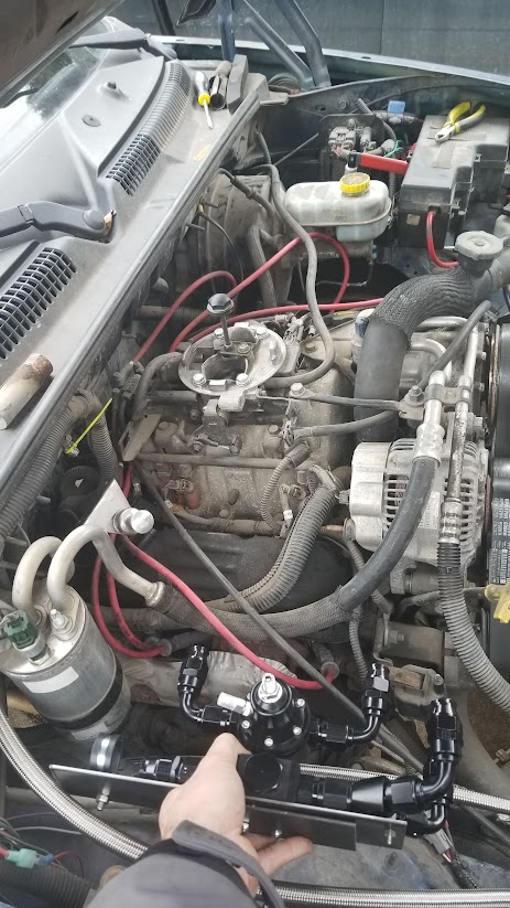
I have the bed elevated in the back so I can get to the fittings - sitting on a pair of 3" red clay bricks. I really need to pick the whole thing up about 6 inches but it's a wee bit heavy to do that myself, even using the floor jack. I have the bracket made to mount the fuel pressure regulator, just need to drill a couple holes and put it on the truck. I also need to finish the mounting bracket for the fuel pump/filter assembly.
We primed the dragster engine, so it's ready to go in the car now.
Last edited by magnethead; 01-04-2019 at 11:13 PM.


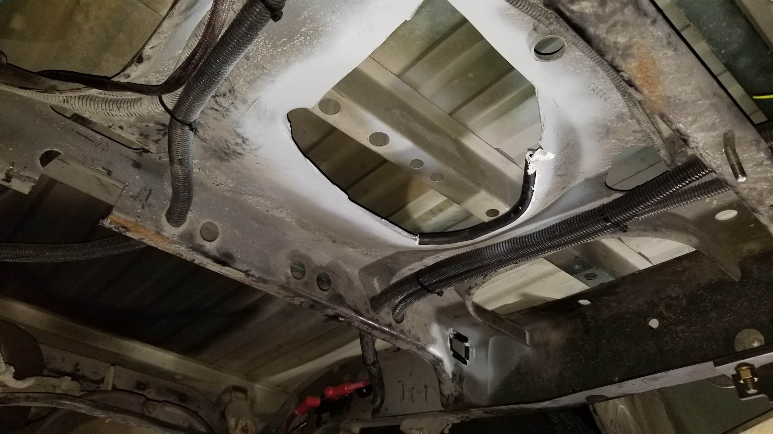
#240
01-08-2019, 02:19 AM
More progress tonight. Opened up the crossmember to make it easier to access the top fittings, made a hole for the return hose to go through, and center-spliced the 2 wires for the fuel level sending unit. Once soldered, 2 layers of electrical tape are applied over the solder joint. Having them offset ensures that they cannot short out under any circumstance. Also, the purple wire cut in the background is from the reverse light circuit. The splices needed to be such that they could not touch that wire - which I need to cap off with heat shrink.