

DIY Onboard Air - 2nd Gen Ram - ARB Compressor and 5 gallon Tank

Thread Starter
|
Champion
Joined: Sep 2011
Posts: 3,891
Likes: 8
From: NorCal
DIY On Board Air -- ARB CKMA12 and 5 Gallon Tank
This is a common air compressor for offroading these days being used for ARB air lockers. Additionally, this compressor is able to fill tires.
**Note this compressor cannot properly operate air tools. Specs are 2.18 CFM @ 29 psi. Nominal pressure for air tools is 90 psi.
Choice of tank (size, orientation, number of ports) is vehicle and owner dependent. Use the DIY as a guideline for your configuration.
I wrote this up to document what I've done so far and plan to add any changes as it is only ~90% complete.
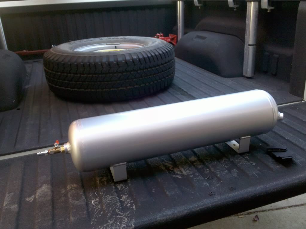
Here is the compressor and tank. Tank purchased off ebay. Shipping is the most inhibiting aspect. I did not find, what I thought, good deals from offroad shops or other stores. Best bet for low dollar, decent tank, is a semi-truck junkyard or salvage yard, such that you can get an air suspension tank. They are already rated for high pressure and plenty of ports. Mounting straps even accompany them. Unfortunately, I couldn't get one of these due to travel distance.

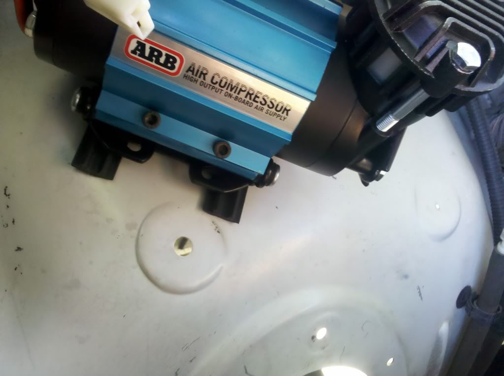
Use mounting plate to locate the compressor install spot. You can see my pilot holes drilled. I had already prefit for this lcoation.
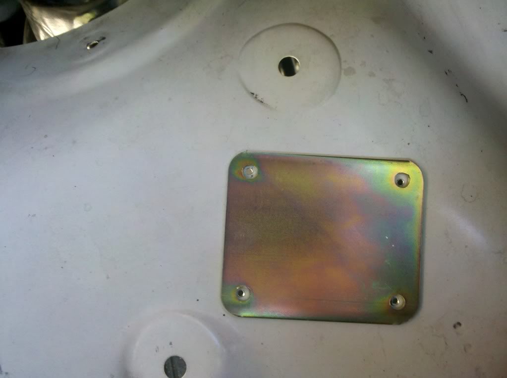
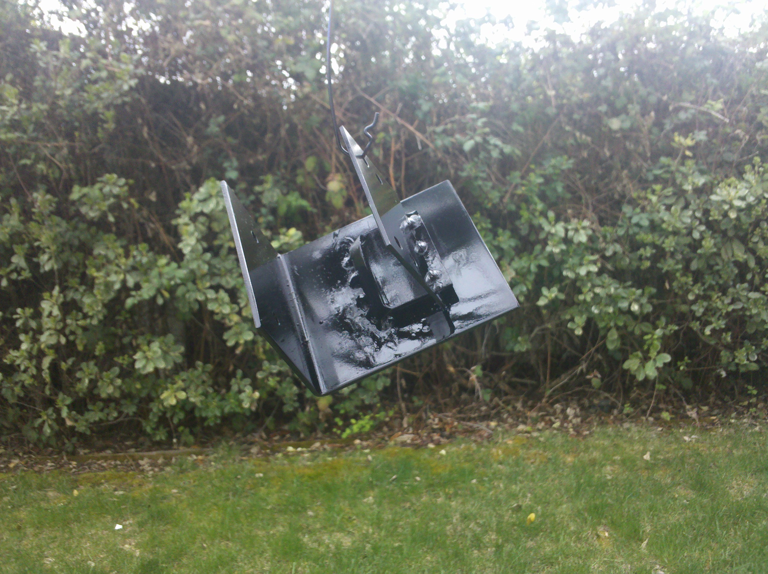
I went and painted the mounting plate
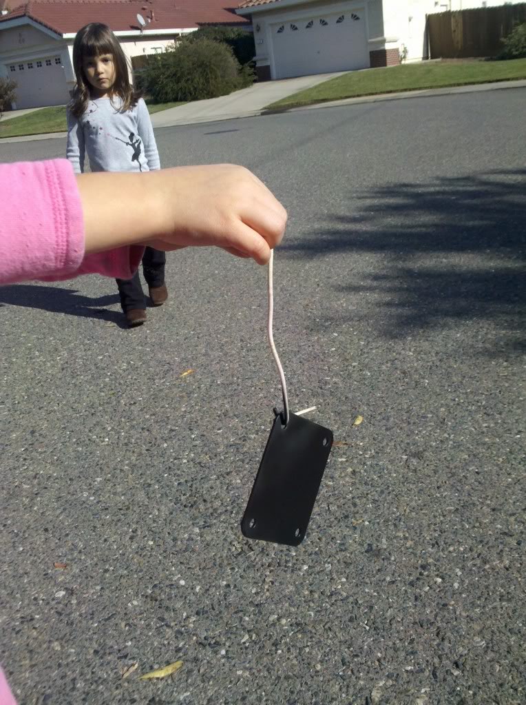
I had some rubber laying around (from my thule rack system) and used for vibration isolation.
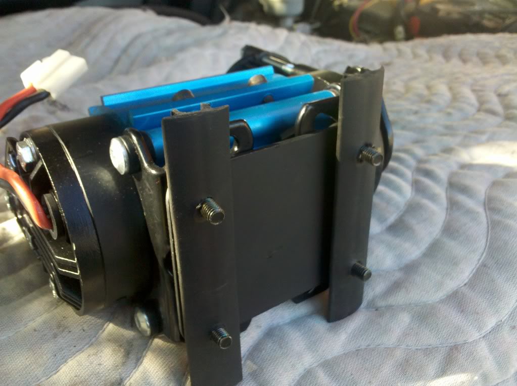
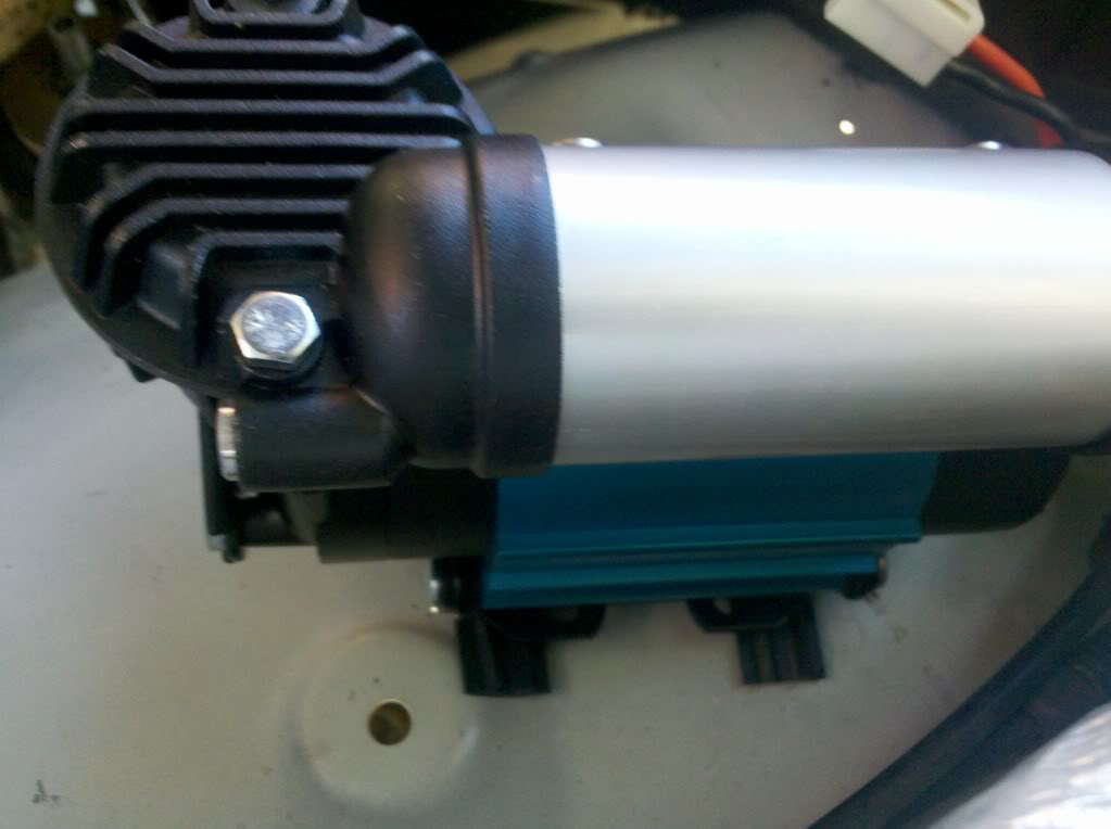
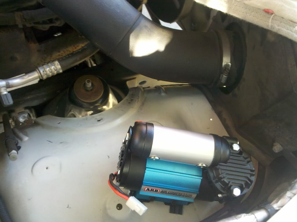
Set in place with mounting plate and rubber.
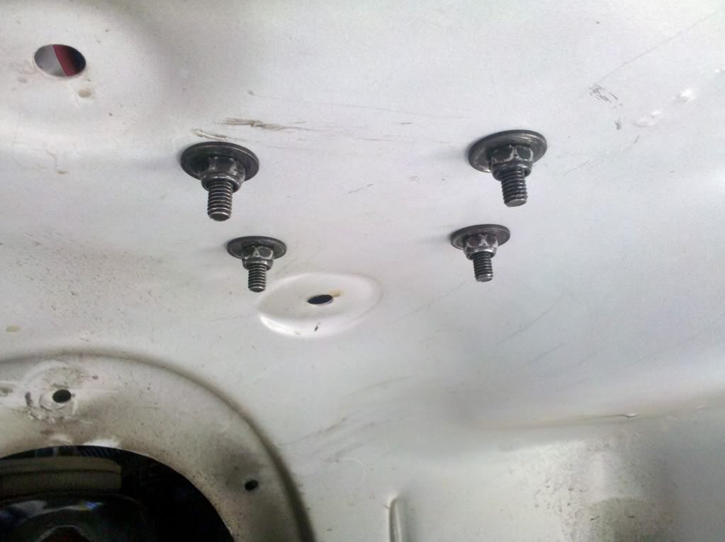
Bottom side of the wheel well. Those of you with wheel well covers, you'll have to remove them. You can get replacement grommets at Autozone. They are 1/4" size and come in packs of 10. They have a phillips head screw that engages and spreads the wings.
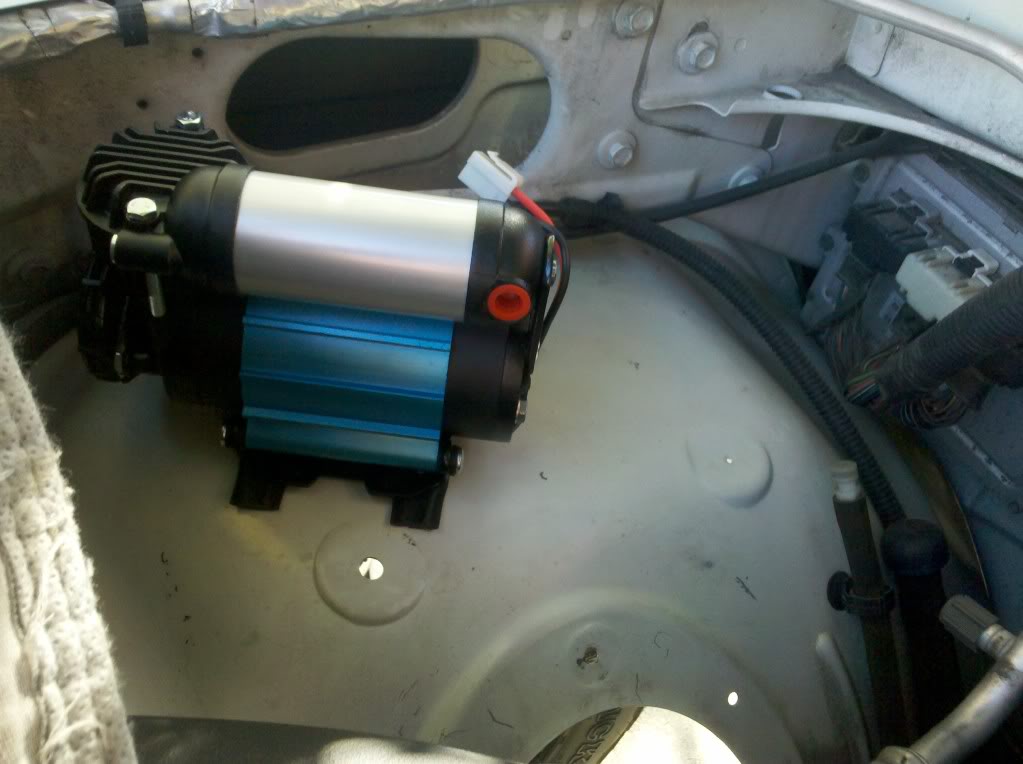
Wiring installed. Added the wiring conduit for protection, ease of routing and identification. Note that the relay is mounted to the wheel well (black box on the left).
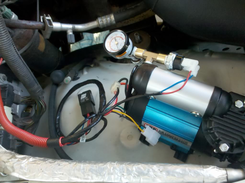
Current setup has a T-fitting, the pressure switch that came with the compressor, and a cheap pressure gauge. All 1/4" npt.
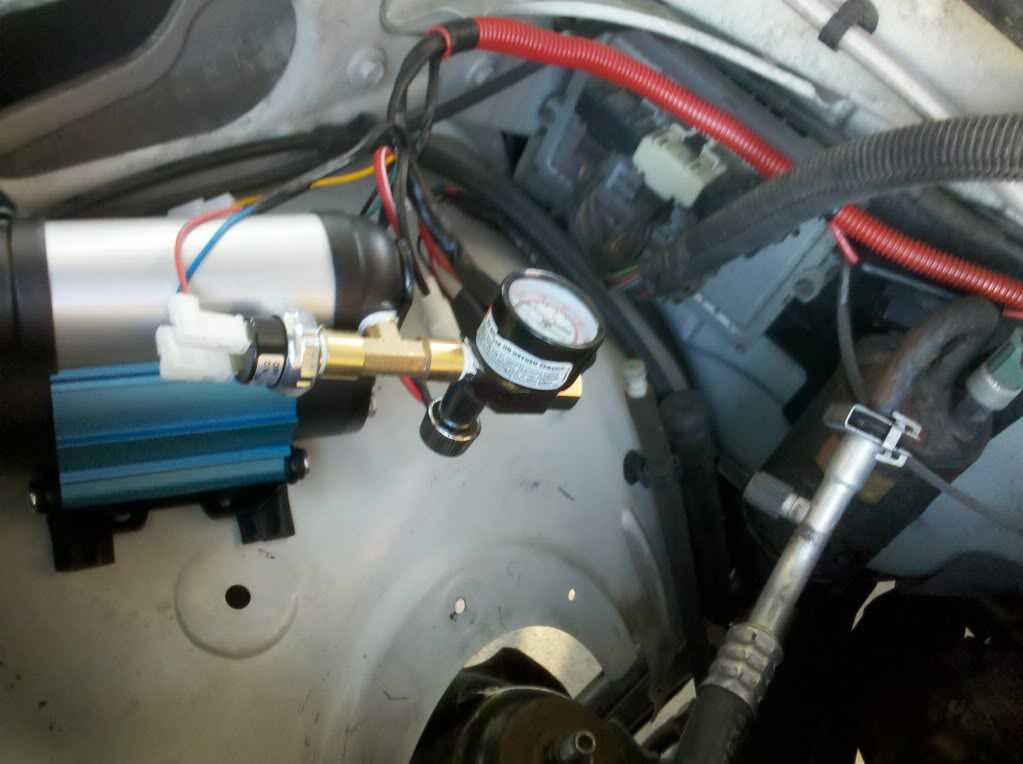
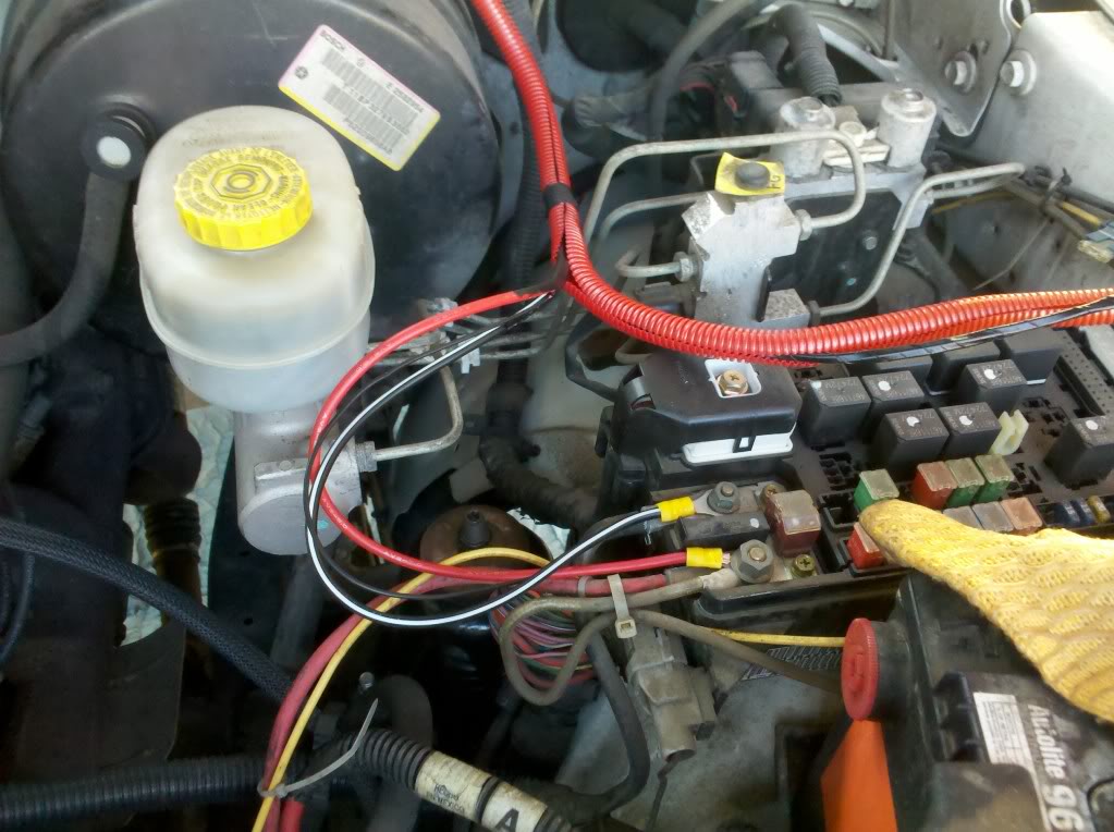
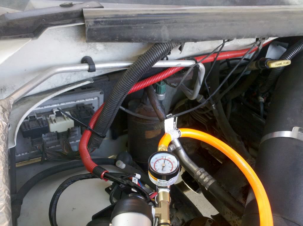
Wiring for Hot and Ground. The conduit off to the right is the harness that goes into the firewall. That location back behind the brake master cylinder.
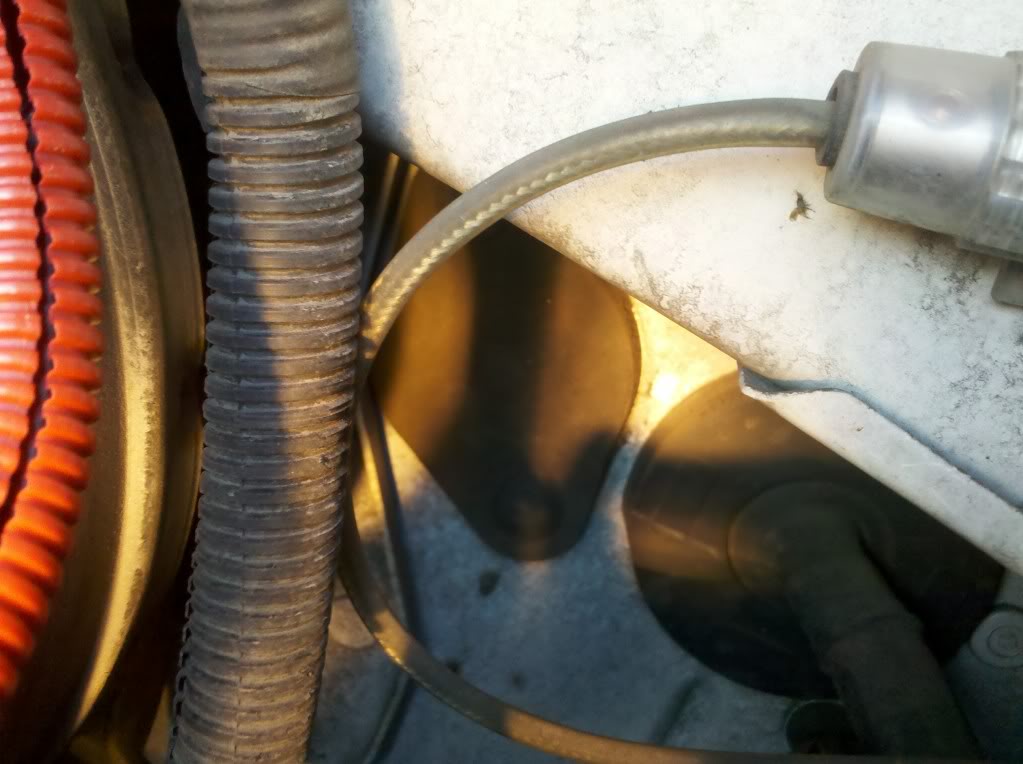
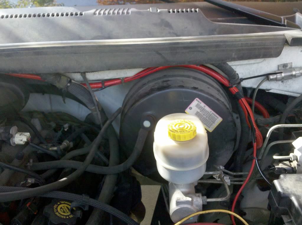
Fire wall access. I poked through the diamond shaped rubber on the left. The hole for the hood cable was maxed out.
So now wiring inside the cab. This is the wire bundle right on the steering column upon removing the kick panel. Three screws across bottom, then lift panel straight out and up.
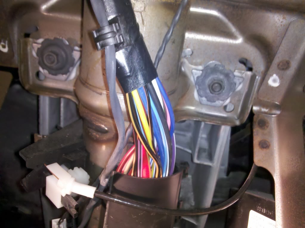
Used the Black and Yellow wire for Dash Illumination!!
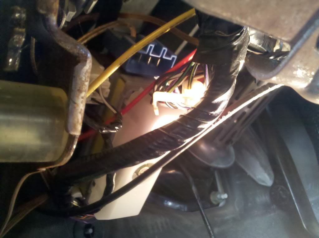
Tried to use Black and Orange for Ignition. THis one did NOT work. See next picture for correct wire, Dark Blue!!
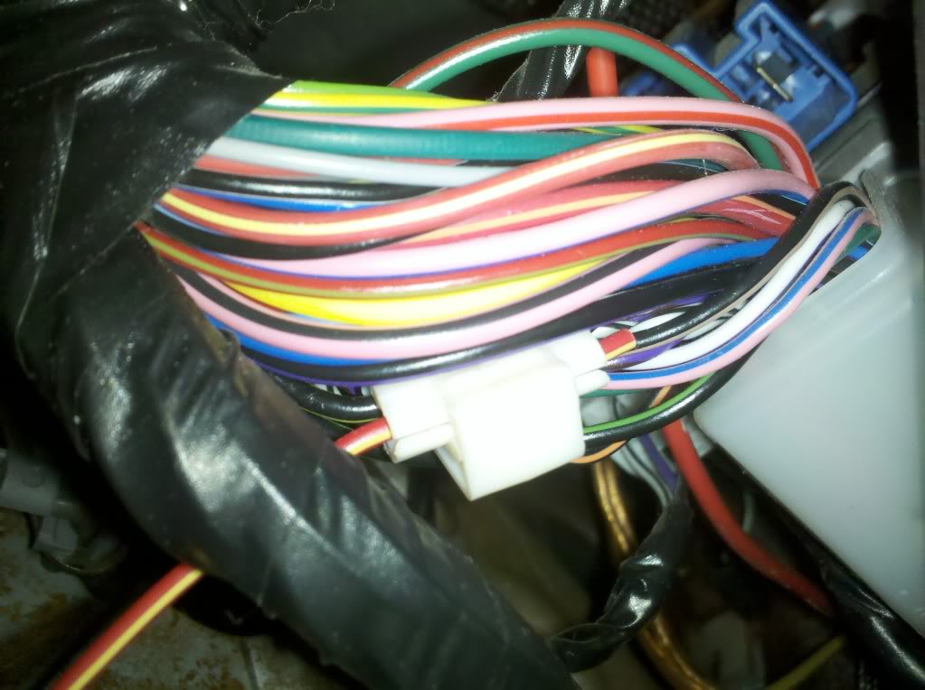
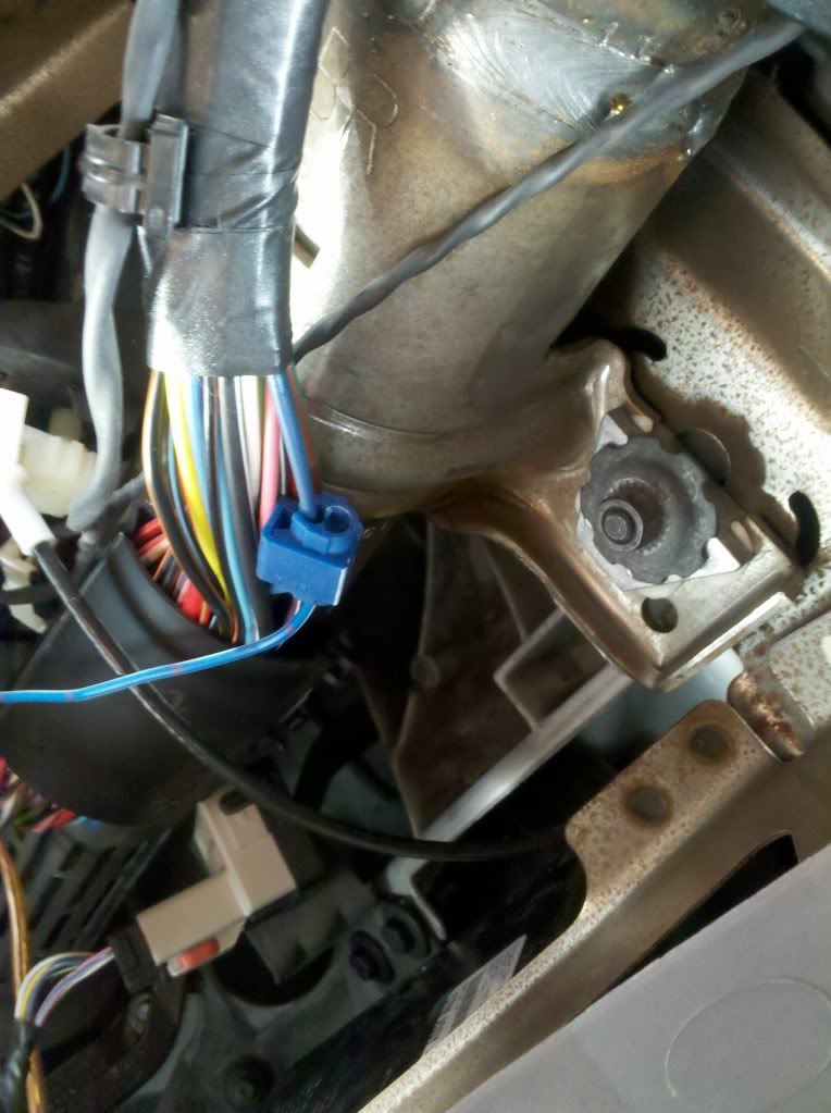
Used the small DARK Blue wire for Ignition.
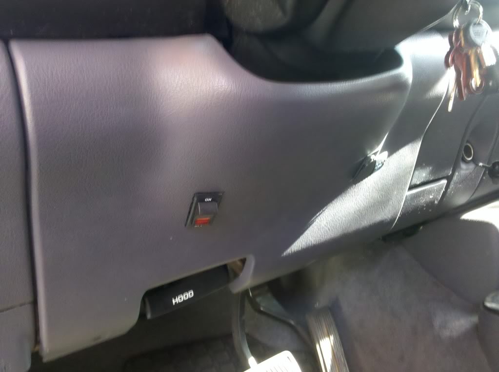
Kick Panel done. Left switch is Aux light in rear. Right switch is the compressor isolator switch. Start vehicle, then turn on switch for compressor to run.
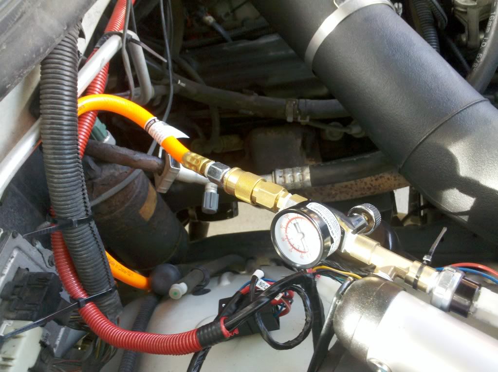
System tested with air line hooked up. Got 100' from HD for ~$25. Red wiring conduit all zip tied in place.
Zip tied on Driver Side.
Added Quick Connect at Comopressor for eash removal or changes in the future.
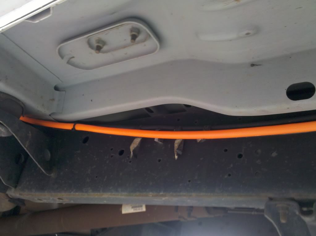
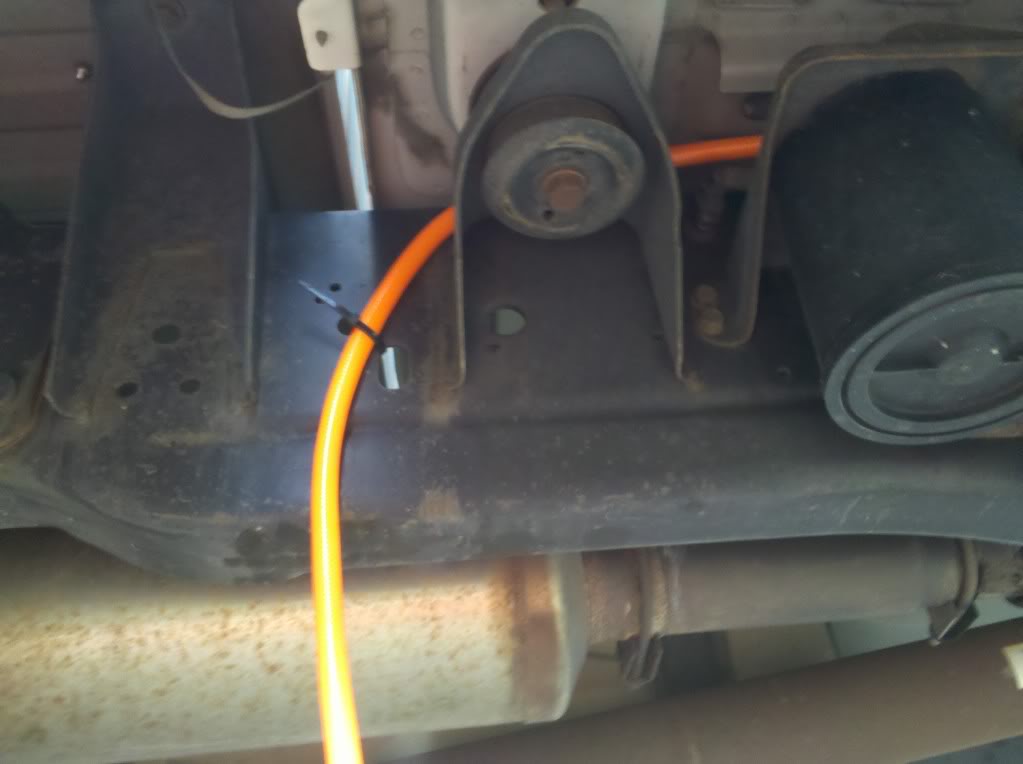
Routed hose down under passenger side. Zip tied to existing vacuum lines and emissions schtuff.
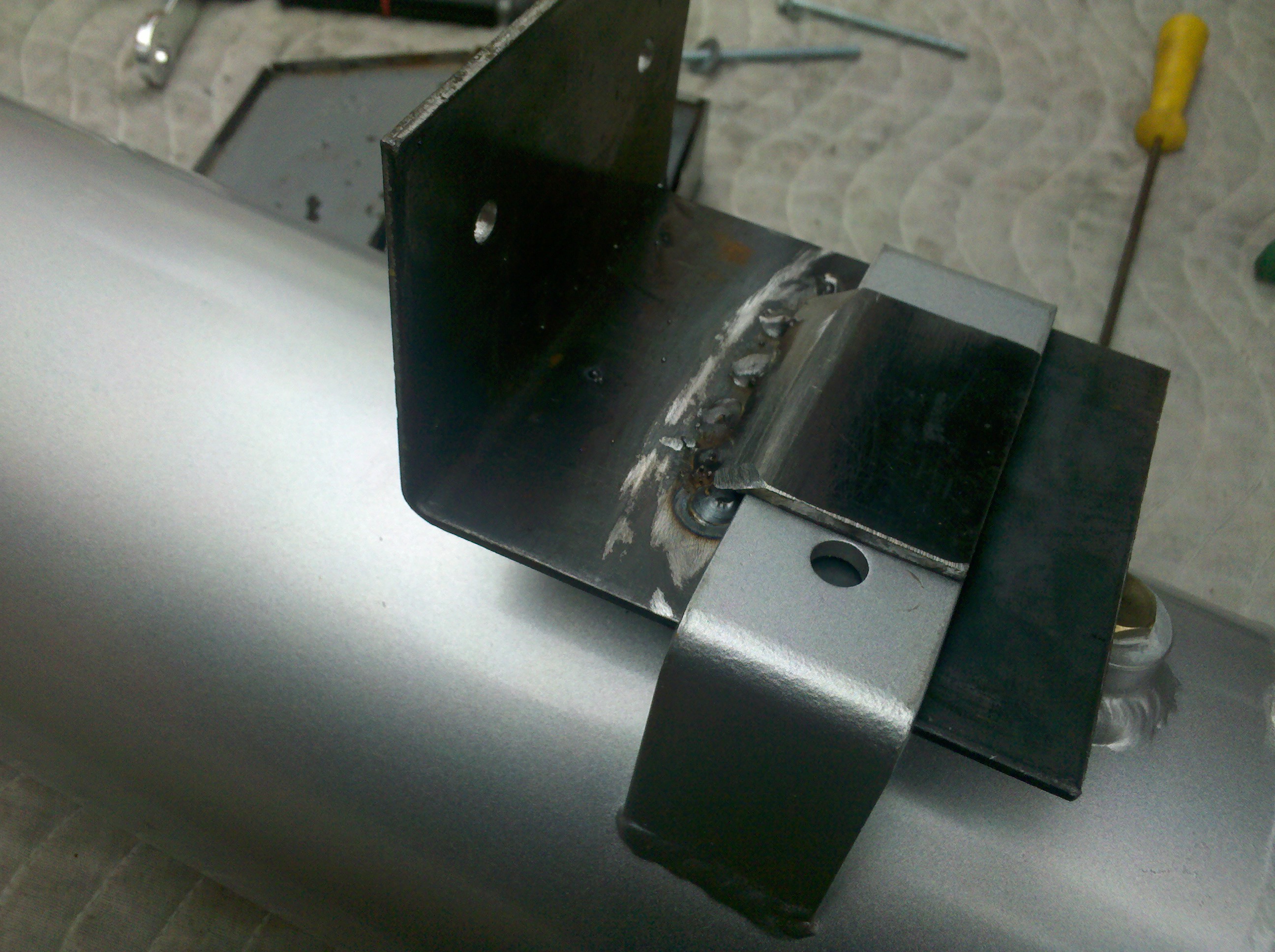
5 gallon tank getting prepped.
More to come. Current system is operational. My hose is rolled up and hung up inside, underneath the bed on passenger side. It's hidden away and partially protected from elements. Plan is to add a 5 port manifold to make for more options.
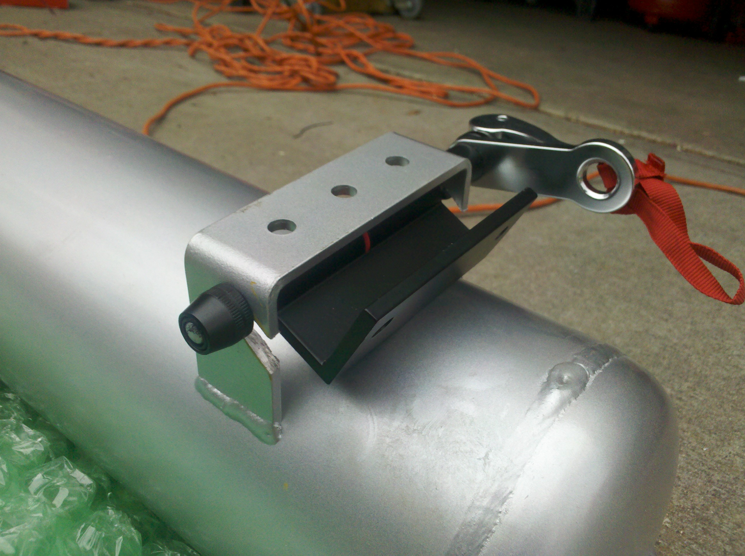
Plan is to route the hose to the tank. This will be once I've finalized tank location. Considering on front of bed, sideways. Then air hose to be run from tank. I'd like to have the tank mounting be quick disconnect too. Some sort of quick release such that the tank could be filled and taken away from the truck if need be to assist other vehicles.
This is a common air compressor for offroading these days being used for ARB air lockers. Additionally, this compressor is able to fill tires.
**Note this compressor cannot properly operate air tools. Specs are 2.18 CFM @ 29 psi. Nominal pressure for air tools is 90 psi.
Choice of tank (size, orientation, number of ports) is vehicle and owner dependent. Use the DIY as a guideline for your configuration.
I wrote this up to document what I've done so far and plan to add any changes as it is only ~90% complete.
Here is the compressor and tank. Tank purchased off ebay. Shipping is the most inhibiting aspect. I did not find, what I thought, good deals from offroad shops or other stores. Best bet for low dollar, decent tank, is a semi-truck junkyard or salvage yard, such that you can get an air suspension tank. They are already rated for high pressure and plenty of ports. Mounting straps even accompany them. Unfortunately, I couldn't get one of these due to travel distance.
Use mounting plate to locate the compressor install spot. You can see my pilot holes drilled. I had already prefit for this lcoation.
I went and painted the mounting plate
I had some rubber laying around (from my thule rack system) and used for vibration isolation.
Set in place with mounting plate and rubber.
Bottom side of the wheel well. Those of you with wheel well covers, you'll have to remove them. You can get replacement grommets at Autozone. They are 1/4" size and come in packs of 10. They have a phillips head screw that engages and spreads the wings.
Wiring installed. Added the wiring conduit for protection, ease of routing and identification. Note that the relay is mounted to the wheel well (black box on the left).
Current setup has a T-fitting, the pressure switch that came with the compressor, and a cheap pressure gauge. All 1/4" npt.
Wiring for Hot and Ground. The conduit off to the right is the harness that goes into the firewall. That location back behind the brake master cylinder.
Fire wall access. I poked through the diamond shaped rubber on the left. The hole for the hood cable was maxed out.
So now wiring inside the cab. This is the wire bundle right on the steering column upon removing the kick panel. Three screws across bottom, then lift panel straight out and up.
Used the Black and Yellow wire for Dash Illumination!!
Tried to use Black and Orange for Ignition. THis one did NOT work. See next picture for correct wire, Dark Blue!!
Used the small DARK Blue wire for Ignition.
Kick Panel done. Left switch is Aux light in rear. Right switch is the compressor isolator switch. Start vehicle, then turn on switch for compressor to run.
System tested with air line hooked up. Got 100' from HD for ~$25. Red wiring conduit all zip tied in place.
Zip tied on Driver Side.
Added Quick Connect at Comopressor for eash removal or changes in the future.
Routed hose down under passenger side. Zip tied to existing vacuum lines and emissions schtuff.
5 gallon tank getting prepped.
More to come. Current system is operational. My hose is rolled up and hung up inside, underneath the bed on passenger side. It's hidden away and partially protected from elements. Plan is to add a 5 port manifold to make for more options.
Plan is to route the hose to the tank. This will be once I've finalized tank location. Considering on front of bed, sideways. Then air hose to be run from tank. I'd like to have the tank mounting be quick disconnect too. Some sort of quick release such that the tank could be filled and taken away from the truck if need be to assist other vehicles.
Last edited by Wh1t3NuKle; Nov 15, 2011 at 11:56 AM. Reason: Added note for no air tool capability, 2 typos
Thread Starter
|
Champion
Joined: Sep 2011
Posts: 3,891
Likes: 8
From: NorCal
Reserved Post for later
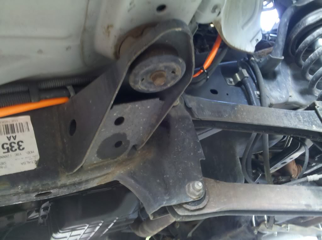
I finally got around to mounting the tank after various mockups. Having recently removed the spare tire, much more room was available then originally thought. Here you go.
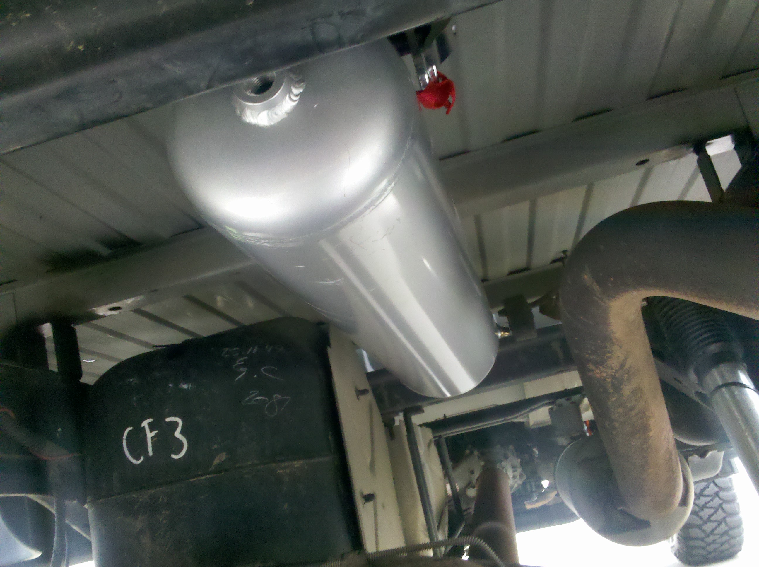
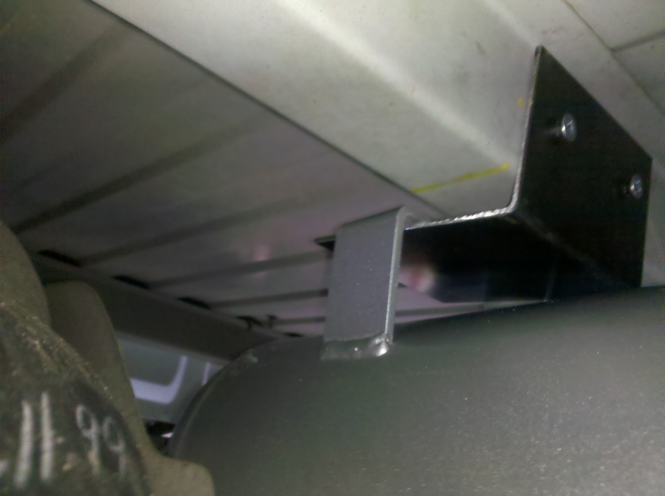
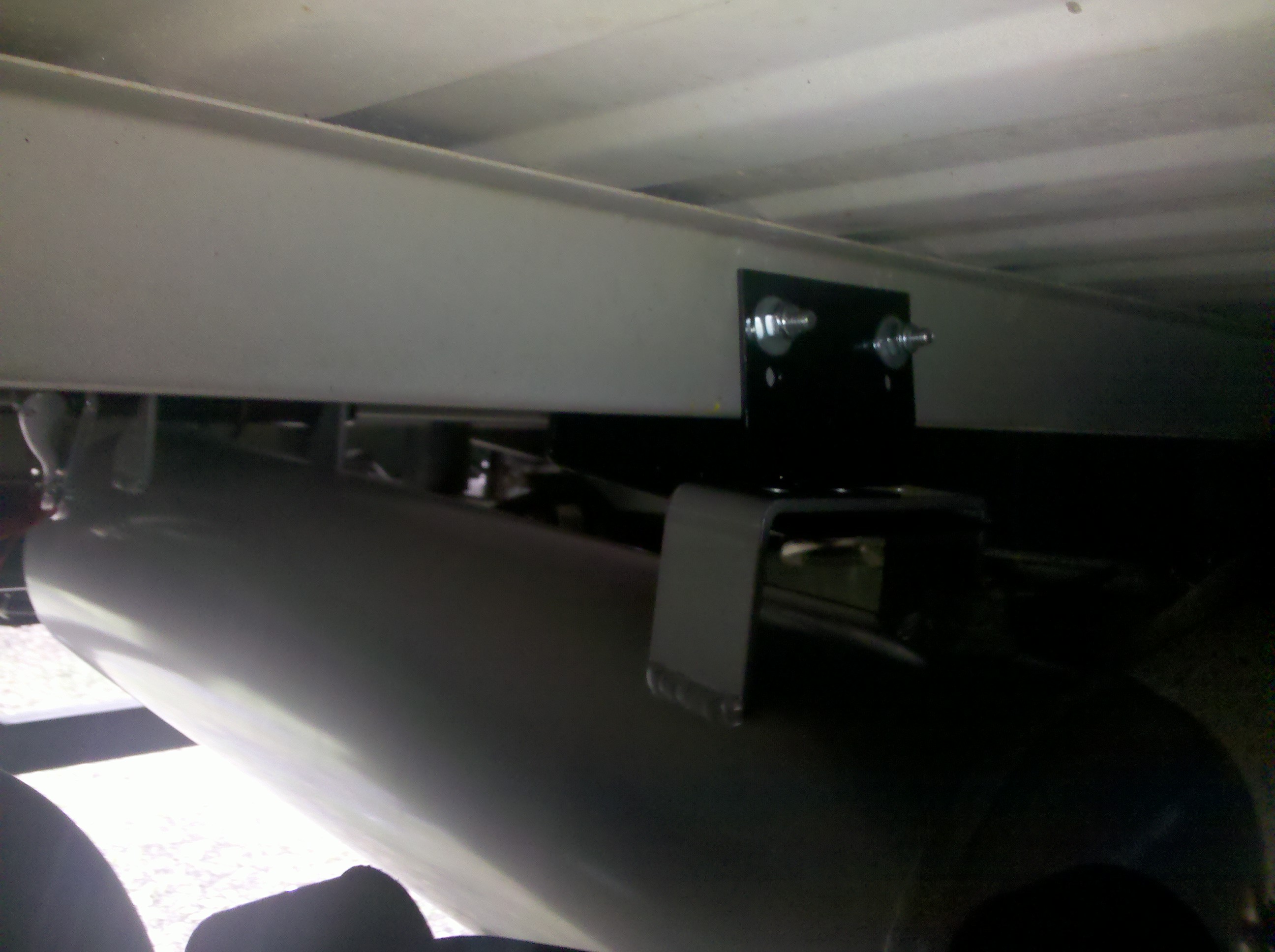
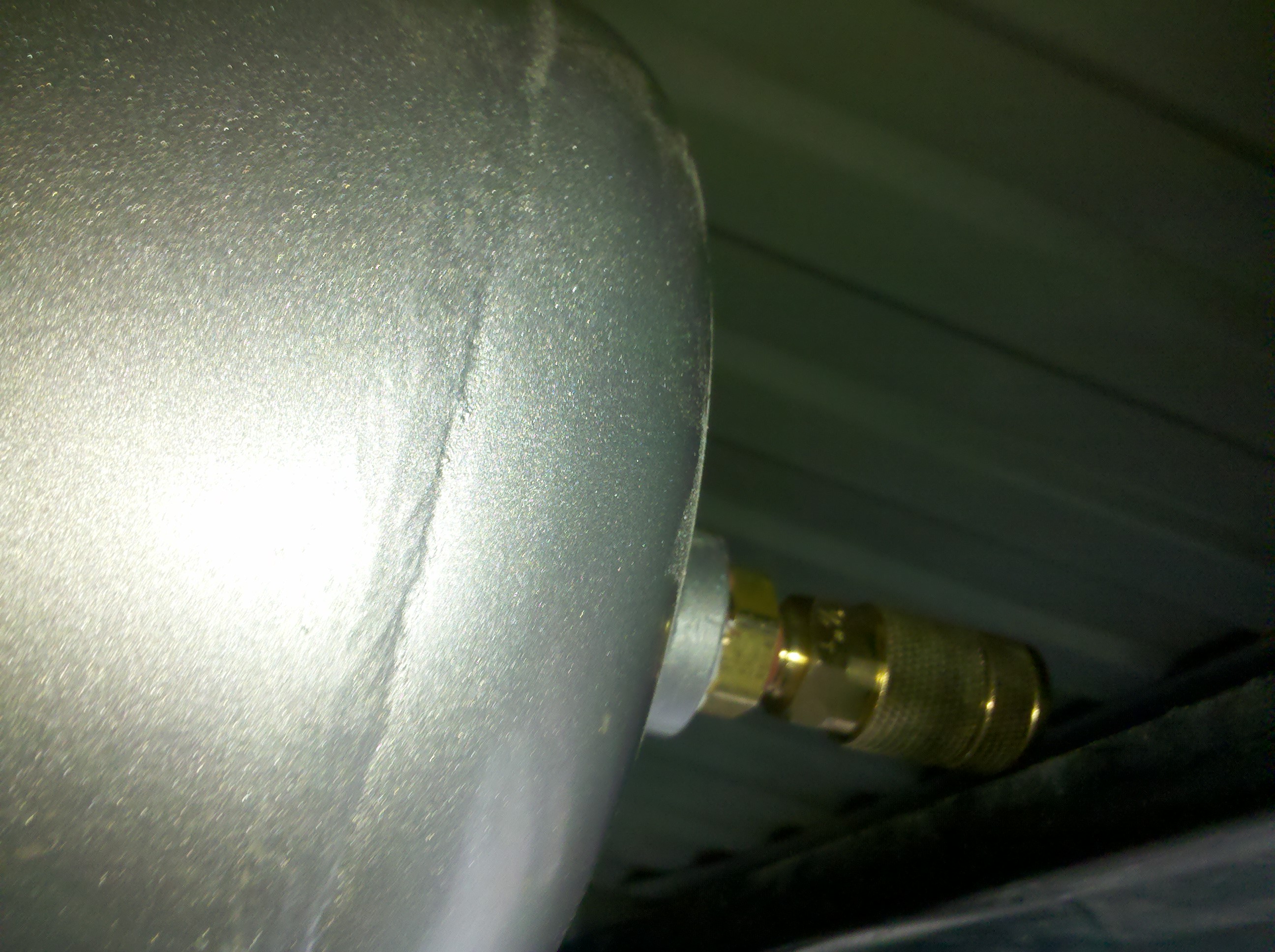
I finally got around to mounting the tank after various mockups. Having recently removed the spare tire, much more room was available then originally thought. Here you go.
Last edited by Wh1t3NuKle; Mar 26, 2012 at 02:53 AM. Reason: Update for Tank
Administrator


Joined: Apr 2010
Posts: 87,487
Likes: 4,223
From: Clayton MI
OOOooooooo, cooooolllll. Onboard air is always a plus. Looking forward to seeing this one complete. Gotta do some tests.  See how long it takes to air your tires up from 10 PSI, to whatever road pressure you use.
See how long it takes to air your tires up from 10 PSI, to whatever road pressure you use.
Thread Starter
|
Champion
Joined: Sep 2011
Posts: 3,891
Likes: 8
From: NorCal
Place your bets!!
The orange wire was for the dimmer control. It would have been used if I had not found the Black/Yellow, which was directly for Illlumination. Much appreciated for that wiring diagram though.
Champion


Joined: Oct 2009
Posts: 4,717
Likes: 10
From: N/A
Your welcome for the diag. One thing I did not see was a water separator, you might want to install one between the comp and the tank; or is it in your plans?
Trending Topics
Thread Starter
|
Champion
Joined: Sep 2011
Posts: 3,891
Likes: 8
From: NorCal
I have tossed that back and forth. The tank has a drain on it. Think its a necessity or "just a good idea" kinda thing? Just didn't think the volume warranted it. However, I'm open to your wit and charm to convince its something good to do. I'm not opposed to it at all.

I would love to run this setup in my toolbox and mount the tank below the toolbox. What else would need to be done to be able to run air tools, just the size of the tank? or would I need to look at a bigger compressor?
Thread Starter
|
Champion
Joined: Sep 2011
Posts: 3,891
Likes: 8
From: NorCal
Here is the specifications for the ARB compressors.
http://www.arbusa.com/uploads/PDF/ai...rTechSpecs.pdf