


pcm ?
#3
 02-11-2011 | 10:12 AM

Thread Starter
|
Registered User
Joined: Jul 2010
Posts: 37
Likes: 0
From: PA
In the morning when I go to start it if its cold out i turn the key to the on position and let it sit my check engine light will start to blink for like 5 mins or so depending on how cold it is then it will stop the check engine light will go off and then i can start it lol. runs good after that
#4
02-11-2011 | 10:15 AM
Administrator
Joined: Apr 2010
Posts: 82,710
Likes: 3,425
From: Clayton MI
#6
02-11-2011 | 12:09 PM

The other problem with this method is that the hairdryer will impart a serious ESD charge on all the components inside and, since the PCM is directly grounded to chassis, ground, it will build up the charge and rapidly discharge the high voltage static charge >25,000 volts.
Again, please do not mention or inform anyone to use a hair dryer to warm up ANY electronic devices for, it will induce failure at the micro circuit traces, the wirebonds, smaller diodes, ICs, LOGIC circuits, RAM, VRAM, PRAM etc.
If you want to properly test your PCM, I recommend you disconnect the NEG battery terminal and wait 3 minutes for all power to drain.
REMOVE CONNECTORS AT PCM. (There's three large connectors, Black, White, Gray)
REMOVE PCM
Take PCM into the house and let it warm to AMBIENT / ROOM temp for a while. Let it totally thaw out and become dry.
When it's fully warmed up and totally dried out:
INSTALL PCM into vehicle.
ATTACH connectors
ATTACH NEG (-) BAT terminal to BAT.
NOTE: Prior to attaching the NEG terminal, make sure all lights, all doors are closed, the dome light is off, the radio is off etc, prior to connecting the negative battery cable.
TEST: Start vehicle.
<IF> vehicle starts up without issue, you've got a problem at the PCM level.
<IF> vehicle FAILS to start up, it may not be PCM related.
REPEAT TEST FIVE TIMES to rule out a bad connection.
<IF> in most test runs, it starts without issue, you now know for sure the problem is rooted at the PCM level. So, if you get 4 out of 5 starts, the problem is most likely rooted at the PCM.
<IF> in most test runs, it still exhibits the same symptoms, I'd be checking the relays in the PDC / Power Distrubution Center per SPEC or Haynes Manual. There's a method of testing those.
That's where I'd be starting. Let me know how you make out and what the test results are.
CM
Last edited by cmckenna; 02-11-2011 at 12:14 PM. Reason: Test info
#7
02-11-2011 | 01:51 PM
Thread Starter
|
Registered User
Joined: Jul 2010
Posts: 37
Likes: 0
From: PA
Trending Topics
#8
02-11-2011 | 02:27 PM

Banned
Joined: Jul 2010
Posts: 123
Likes: 1
DO NOT USE A HAIRDRYER on the PCM. This is the second time I've had to mention that's not a good idea because, when the PCM is cold and you blast it with hot air, it's going to condense on the inside of the circuit in the PCM case and, water droplets will form thus creating potential for shorting out the PCM.
Again, please do not mention or inform anyone to use a hair dryer to warm up ANY electronic devices for, it will induce failure at the micro circuit traces, the wirebonds, smaller diodes, ICs, LOGIC circuits, RAM, VRAM, PRAM etc.
REMOVE CONNECTORS AT PCM. (There's three large connectors, Black, White, Gray)
Last edited by stands2p; 02-11-2011 at 02:31 PM.
#9
02-12-2011 | 05:18 PM
never been inside a pcm have you?no.in 1995 the pcm is a SBEC2 and is incased in epoxy thuslol it can not short due to condensation/water.96-up pcm is a JTEC and it to is encased in this epoxy to protect the curcits from water/vibration.
how would he remove 3 connectors?never seen a 95 pcm i see.so ill tell ya.it has only one 60pin sealed connector.
To answer your question Stands.... I have seen the insides and have worked on a couple here and there over the years and, it just so happens that I've got a 96-PCM sitting in front of me. It's got an Al housing in what's called a clam-shell design. It's sealed using RTV gray sealant only at the clam shell cover.
As seen here, there's no epoxy.
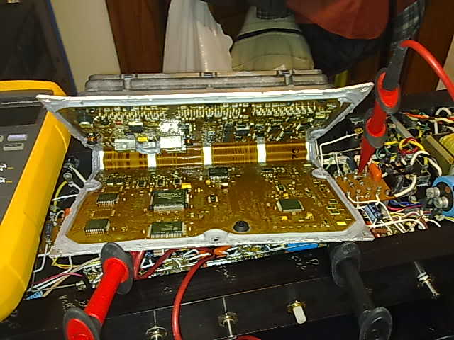
There's no potting compound that protects the circuit components from vibration either as you'd stated. Just thought for the readers who come here I'd set the record straight and show them as well as you what's really going on within a PCM assembly.
This design employs Flex. And, clearly seen are all the SMT components minus through hole connector pins which, directly mount to the flex print vias and, three radial leaded components which are secured by means of mechanical restraints. Some designs use lacing cord, some use special rubber bands and in this application, mechanical clamps are employed.
Here's an example of mechanically securing a cap to a PCB substrate with a two part, high strength epoxy.
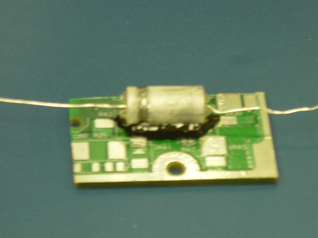
I've used epoxy to secure caps into high vibe profiled electronic assemblies many times such as on Boeing's 787 braking electronics. The assembly mounts at the axle of the aircraft but despite it being an aerospace application, no potting was necessary. The electronic assembly that this cap went into, was not potted.
That cap was the problem due to running high G-load tests that Boeing was asking for and until I was brought in, they'd failed three attempts in securing it to the CCA as it kept flying off during vibe test.
The use of potting compound can be problematic and, depending on design and materials selected, it can induce failure at the solder joints. Even just the drying and / or curing process of those materials can shred the crap out of the components and tear them apart. Flex circuit is not robust and, considering when trying to open a unit that has been potted 100% and, it being of PCB (Glass and Epoxy) material base, that the PCB material de-laminates and the components and traces are ripped to shreds.
The CTE of the potting compound over such a large surface area would stress the solder joints and components and, it would also make these PCMs unrepairable for, if one were to open one up, they would literally rip all the components apart as well as the substrate. There would be no remans on these to which, they're a dime a dozen places that perform this service.
Not only is the TCE a concern here but, so is thermal overheating due to no air flow. The only way around this would be to use a thermally conductive material and, even then, you'd need something to wick the heat away such as a heat sink. This is why this PCM is open on the inside and has a breather vent. This is a convection cooled only device and, if it were potted 100%, it would overheat and kill the components inside.
In this case, the PCM is vented. In fact, pull out a 2nd Gen PCM. Look at the rear panel. Note the breather vent there. That's a breather port to allow for expanding air and moisture to escape. In fact, remove the plug and take a peek inside- no potting.
Hairdryer and ESD:
There is no special EMI / ESD shielding coating used on these PCMs. Those coatings for ESD proofing are filled with carbon fiber and are conductive as are other EMI / ESD coatings.
The components are susceptible to ESD shock and, they are not isolated or shielded either with a special anti ESD coating or mechanical Faraday cage. In fact, when testing for ESD per GM9109P, air discharge voltage of 25kV is applied, it is considered a destructive test. A destructive test is one in which, after the test is run, the assembly will no longer function normally due to inducing failure at the component level.
Some electronic components / devices are so sensitive that they will blow when you get near them within a distance of 3-4 feet just from moving around. While these are not found in this PCM, it's just an example of how some components are extremely ESD sensitive and precaution should be taken into consideration.
Again, the use of a hair dryer blowing hot, dry, charged air near any electronic device is a bad idea - period. Bad idea, bad recommendation. Placing a cell phone that dropped into the swimming pool into a convection oven on low with the door open to bake it out works better than taking a hair dryer to it.
CM
Last edited by cmckenna; 02-12-2011 at 05:55 PM. Reason: Typos
#10
02-13-2011 | 07:22 AM
Banned
Joined: Jul 2010
Posts: 123
Likes: 1
This is incorrect. See below
100% accurate info……
I thought he had a later PCM style thus, the mention of the three connectors as found on a later models. I missed thhe year and, aside from scrutiny on that minute detail, there's your reason for three connectors mentioned.
As seen here, there's no epoxy.
There's no potting compound that protects the circuit components from vibration either as you'd stated. Just thought for the readers who come here I'd set the record straight and show them as well as you what's really going on within a PCM assembly.
let me explain this to you Christopher……..this coating is an epoxy which is used for the encasement(typically dipped or sprayed and then heat cured) of the micro circuitry for the purpose(among others) of protecting against moisture,vibration or any auto fluid/chemical which may find its way into the case.the pcm would not last with out this epoxy coating.
Heres a close-up of a JTEC PCM in which we all can now clearly see this epoxy encasement on the main Motorola mc68hc16z2 microcontroller which would be in the center,lower left is the k4 fuel microcontroller and the two flash proms to the right.
As we can see everthing else said is invalid in regards to the SBEC2/JTEC and is an attempt to sound edjamacated.
EDIT.....for all the SCT users the main Z2 CPU is what gets burned when loading a tune.
Last edited by stands2p; 02-13-2011 at 10:53 PM.