


Connector Pinouts in manual are wrong?

I'm trying to troubleshoot my drivers door switch panel, but looking at the manual's connector pinouts they appear to be wrong.
The manual shows 12 pins, my connector has 12 pins, but they don't match up with what's in the book.
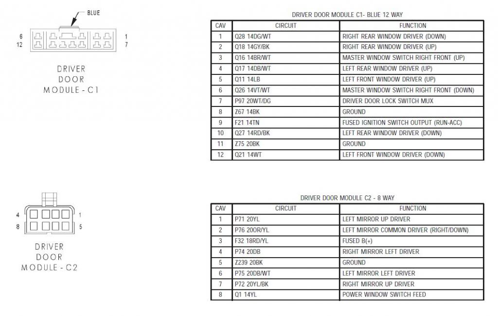
This is what the book shows.
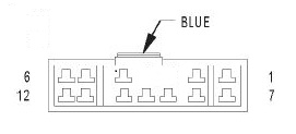
But this is what mine actually looks like, and the pin numbers don't match up...so wtf? do I have the wrong manual?
The manual shows 12 pins, my connector has 12 pins, but they don't match up with what's in the book.
This is what the book shows.
But this is what mine actually looks like, and the pin numbers don't match up...so wtf? do I have the wrong manual?

Anybody??
I'm just trying to figure out where to put power to get just the LEDs to come on.
My connector has 12 pins but they aren't in the right order or something....for instance, which pin is number 4??
This just isn't making much sense to me.... the last pin on the top row would have to be pin 5 and not 6.
Moderate User


Joined: Oct 2008
Posts: 17,003
Likes: 21
From: Albany, NY
That's strange. They do match up to whats in the book, but the book doesnt match up to itself.
If the center hole for the puch connector is pin #4, the manual shouldnt show that as having a connection...lol
I do know the wire colors were slightly diff from year-year, but their place is all the same.
If you want door led's to come on when you open up the door, NONE of those connections will do that for you unfortunately. You'll need to tap into the dome light circuit which is inside the truck. Then routing the wire through the connectors is impossible...which is why I haven't done it.
wait...dont we have a door pocket light? maybe that's my beater car I'm confusing with???
It's not to make the lights come on when the door is open, I'm trying to figure out what's going on with my switch LEDs.
From time to time they just go out..... 4 out of the 5 anyway, simply are not on. The windows and locks work fine but 4 of the switches aren't illuminated.
Eventually they will come back with no rrhyme or reason as to why they go out in the first place.
They went out a couple of days ago, and I unplugged the module to try and troubleshoot it to no avail, I did nothing but plug it back in and the lights are on again functioning as they should.
At this point I'm almost entirely convinced that it isn't the LED mod or the drivers door module at all, but something in the wiring elsewhere.
They could have done this when the LED's were the factory green but they were so dim I never would have noticed.
I'm really just trying to figure out which pins are power and ground so I can put 12V on it and see if the LEDs still light up.
Almost moot now since they are working again, but give it some time and they will go out again.

Registered User
Joined: Jan 2013
Posts: 6
Likes: 0
I can't help with your problem, but thank you two for the above chart and photo of your harness. That helps me huge with a problem of crossed wires I am having! I think I may be able to finally get my controls working the correct window now.
When you get your problem solved post the results here.....theres a good chance you can help me with mine since I have no god damn pin 4 and the diagram completely doesn't match what I have.
I just don't want to risk further complicating my problem by applying power ***** nilly all over the place, especially if you've already figured out the wiring
I just don't want to risk further complicating my problem by applying power ***** nilly all over the place, especially if you've already figured out the wiring
Trending Topics
Registered User
Joined: Jan 2013
Posts: 6
Likes: 0
You do have the correct harness. Look from the left corner, theres two pins in the top row before your gap. Then there's three pins on the right hand side and seven all along the bottom. Thats the same as I have and your picture matches the first diagram from your posts. So if you go left to right along the top row you have pins 5,4, -, -, 3,2,1 and then on the bottom you pin 12 directly under # 5 and pin 6 is right below #1.
To answer your power question the LEDS go out if the Tan power (run-acc) is pulled. Atleast thats what I figured out for mine.
My problwm is that my trucks an 07 and has wires from an 02 AND my left rear wires are switched with my right front wires. But your post helped me figure that out and now my windows and locks are perfect!
Last edited by jilane16; Jan 15, 2013 at 11:40 PM.
Thanks, that should help me out a great deal the next time my lights go out.
They're back on again now lol.
If you pull the tan wire the LEDs go out, but does the rest of the module continue to work? Can you still use the windows and such?
They're back on again now lol.
If you pull the tan wire the LEDs go out, but does the rest of the module continue to work? Can you still use the windows and such?