

The Victim Build Thread -- Featuring frame replacement

Thread Starter
|
All Star
Joined: Apr 2013
Posts: 941
Likes: 22
From: Connecticut
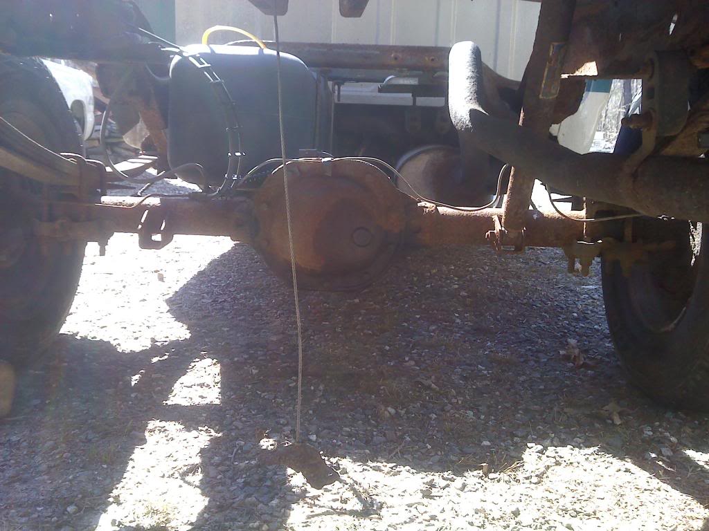
Brake Lines
Every single brake line on this truck is now new. I used SUR&R nickel-copper alloy lines. This is my second time using them; the first time I used them I replaced all the hard lines on a Silverado. They are quite honestly a pleasure to work with. Unless you're trying to match intricate factory tight bends, you don't need a tubing bender at all. They also flare very easily. Here is a video I made (click) which is just a short overview of the lines and the applications.

I actually riveted the rear-bound lines to the inside of the frame. Same thing with the right front brake line. I don't anticipate having to ever remove these lines and if I do for some reason, it's no big deal to grind off the rivets. I'll get pictures of the whole setup soon.
Old Rear End Lines
New Rear End Lines
Every single brake line on this truck is now new. I used SUR&R nickel-copper alloy lines. This is my second time using them; the first time I used them I replaced all the hard lines on a Silverado. They are quite honestly a pleasure to work with. Unless you're trying to match intricate factory tight bends, you don't need a tubing bender at all. They also flare very easily. Here is a video I made (click) which is just a short overview of the lines and the applications.
I actually riveted the rear-bound lines to the inside of the frame. Same thing with the right front brake line. I don't anticipate having to ever remove these lines and if I do for some reason, it's no big deal to grind off the rivets. I'll get pictures of the whole setup soon.
Old Rear End Lines

New Rear End Lines

Last edited by tbugden; Dec 13, 2014 at 09:11 PM.
Thread Starter
|
All Star
Joined: Apr 2013
Posts: 941
Likes: 22
From: Connecticut
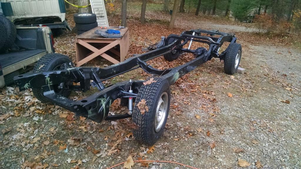
Paint
Did I mention that it's a rolling chassis now? It actually is more complete than this picture. Since this picture I have put up the fuel tank, installed all the steering stuff, and dropped the motor back onto its mounts.
I guess now is a good time to talk about paint.
I used two main paints for the frame and all major components. SPI Epoxy Primer coats the entire outside of the frame by brush, while Eastwood's Internal Frame Coating takes care of the inside of the frame. The only other paint that got significant use was VHT caliper paint, which I used for the drum backing plates front & back as well as the calipers.
Eastwood's Internal Frame Coating is green as you can see here. Two cans were just barely enough to put a coating in the boxed front of the frame. Four probably would have been better, but I'm not that concerned about the inside of the frame.
Did I mention that it's a rolling chassis now? It actually is more complete than this picture. Since this picture I have put up the fuel tank, installed all the steering stuff, and dropped the motor back onto its mounts.

I guess now is a good time to talk about paint.
I used two main paints for the frame and all major components. SPI Epoxy Primer coats the entire outside of the frame by brush, while Eastwood's Internal Frame Coating takes care of the inside of the frame. The only other paint that got significant use was VHT caliper paint, which I used for the drum backing plates front & back as well as the calipers.
Eastwood's Internal Frame Coating is green as you can see here. Two cans were just barely enough to put a coating in the boxed front of the frame. Four probably would have been better, but I'm not that concerned about the inside of the frame.

Thread Starter
|
All Star
Joined: Apr 2013
Posts: 941
Likes: 22
From: Connecticut
Tomorrow I may be welding the floor in! I have pictures of the low-budget process of floor pan forming and replacement. So far it has gone awesome. The floor test fit better than I could ever have hoped. That's the last major thing I have to do!!! Still have to make the other 7 body mounts (see this thread), bolt up the front differential, transmission, make and run the fuel supply line and vent line, run the rear wiring back, install the rear driveshaft, connect up exhaust, adjust the rear brakes, fill the diffs, replace a couple heater hoses, replace the clutch master/slave assembly, reinstall the cab on the frame, install the front parking brake cable, connect all the wiring, fill motor with oil, install master cylinder and associated lines, test start, install the fenders and radiator support, install dash, headliner, and rest of interior, along with 20 or 30 other things I forgot, and I'll be DONE!!!
And I'm coating everything with Fluid Film. This thing will not ever rust again. Okay, it will, but it's got a lot of life ahead of it.
I still have plenty of other stuff to post up...pictures for days. Eventually it will all be here.
And I'm coating everything with Fluid Film. This thing will not ever rust again.
Okay, it will, but it's got a lot of life ahead of it. I still have plenty of other stuff to post up...pictures for days. Eventually it will all be here.
Thread Starter
|
All Star
Joined: Apr 2013
Posts: 941
Likes: 22
From: Connecticut
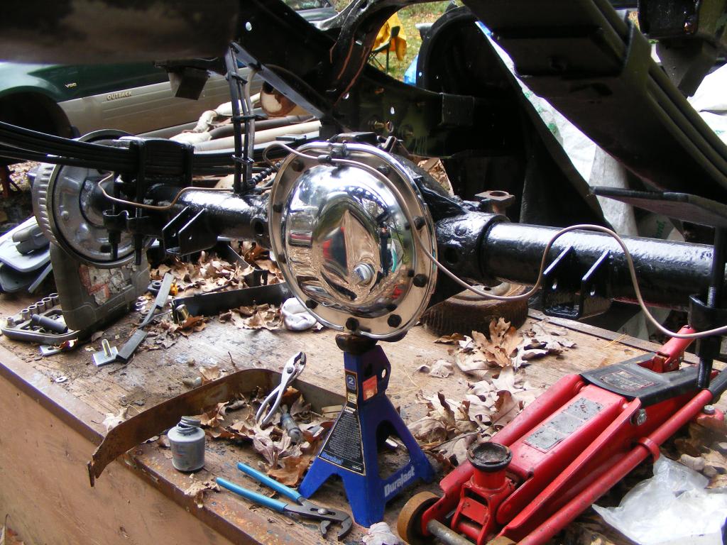
Making New Transmission Mount
As with other parts of this truck, the transmission mount was completely rotted. I made a new one from a piece of the old frame.
First I cut a replacement piece of steel out of the front crossmember of my old frame, approximately copying the dimensions of the old one.
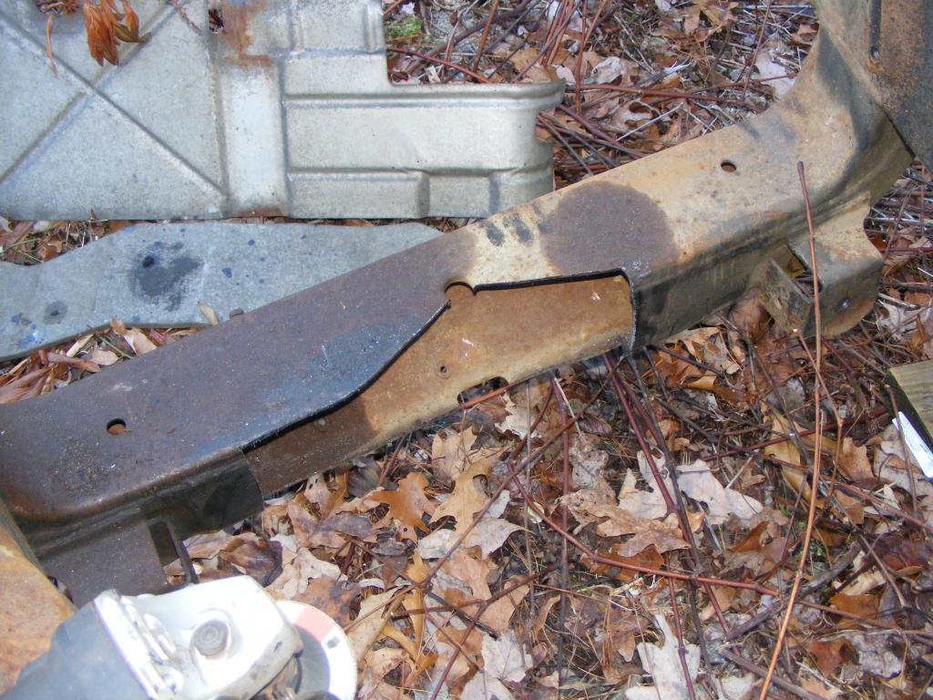
I ground off all the welds from the block to which the transmission actually bolts to because I planned to reuse that piece. That was fun. Well, I mean sparks are fun to make, but it gets old when you have to grind off about a foot of thick welds.
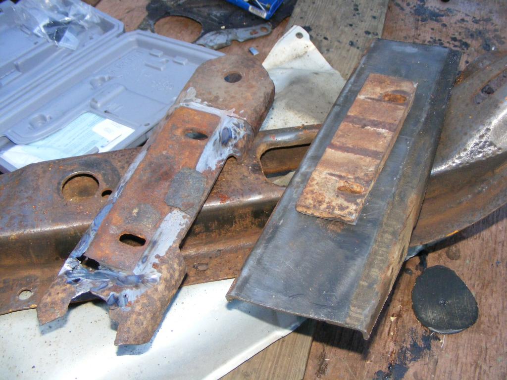
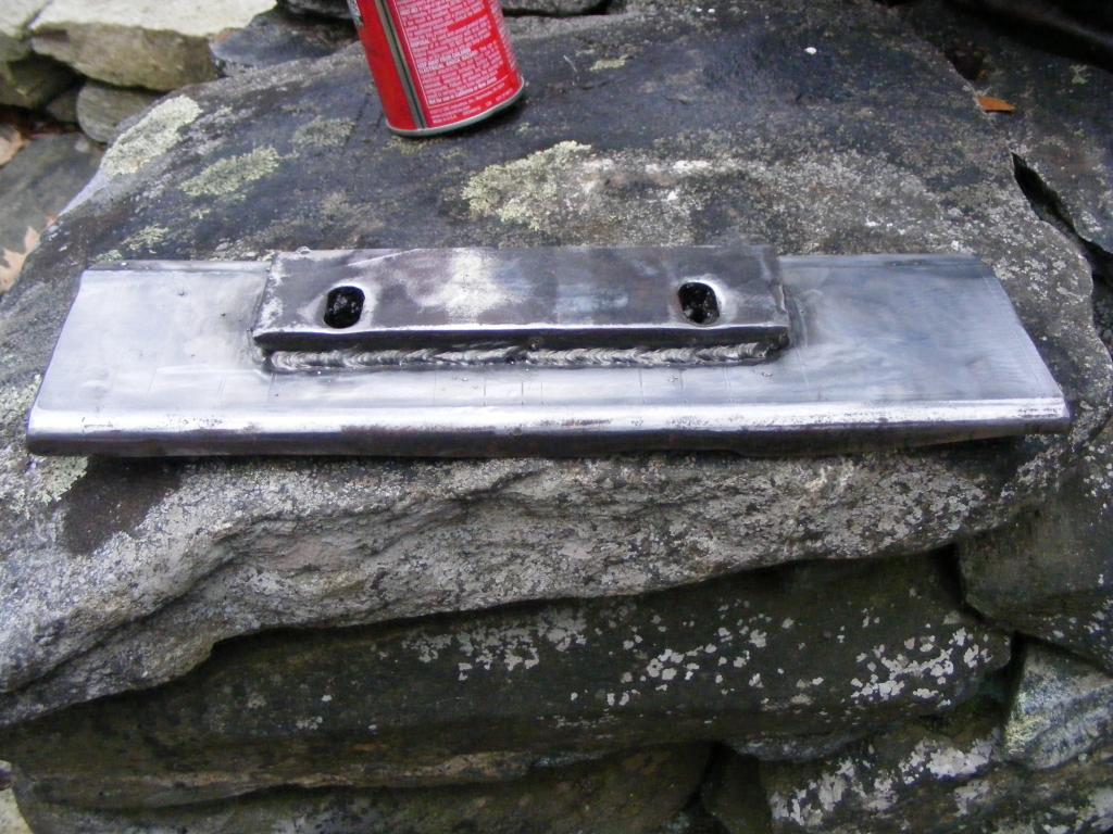
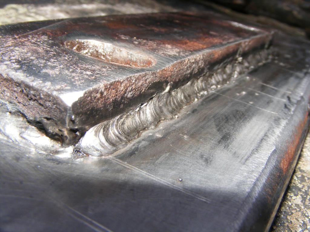
I used the rotted piece as a guide and traced the holes to cardboard. Only problem was the right side had no hole to trace; that side was completely rotted to pieces. So I more or less estimated. I cleaned up both pieces and welded them together. These are some of my better welds, not great, but decent I think. It doesn't really matter for this...I could've welded it just at the corners and I bet it would be fine. This was more for practice.
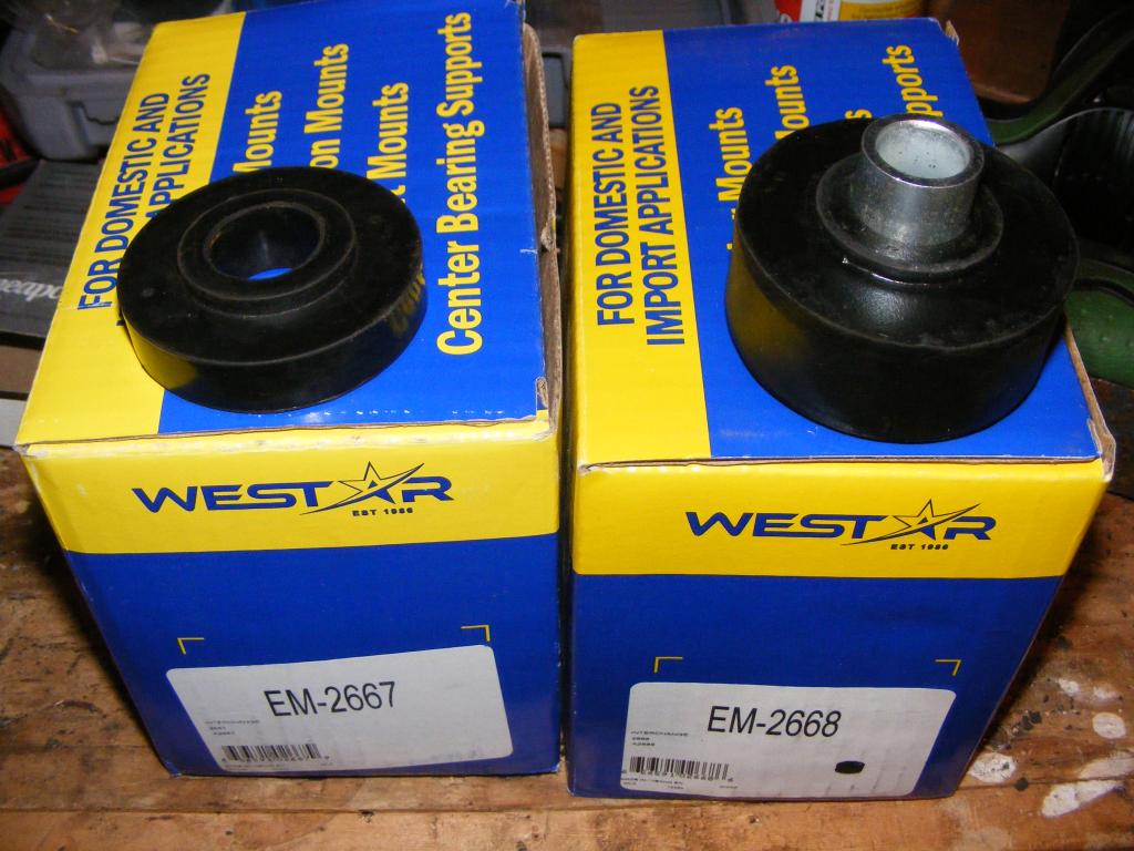
These are the replacement isolators I used. Westar part # em-2667 for the lowers, Westar part # em-2668 for the uppers. You just have to reuse your washers which even on my rust bucket were plenty reusable.
Bushings
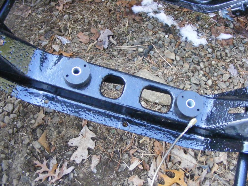
I cleaned up and painted the washers, and used brake caliper grease between all surfaces.
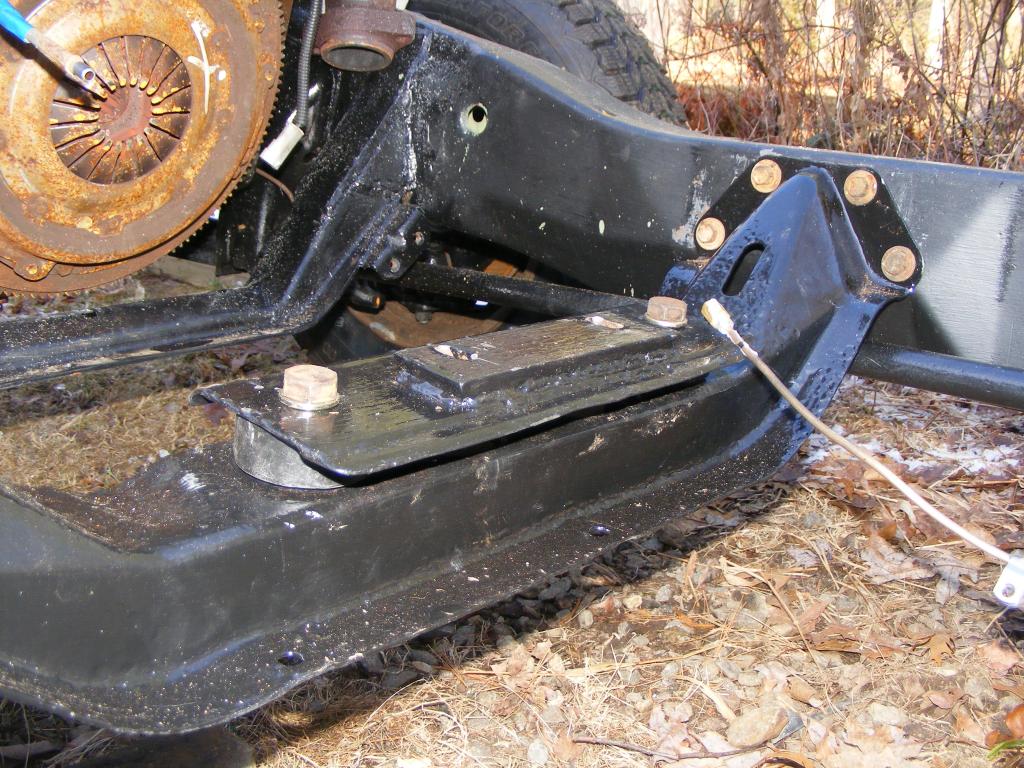
All set to go. Not perfect, but it should do.
As with other parts of this truck, the transmission mount was completely rotted. I made a new one from a piece of the old frame.
First I cut a replacement piece of steel out of the front crossmember of my old frame, approximately copying the dimensions of the old one.

I ground off all the welds from the block to which the transmission actually bolts to because I planned to reuse that piece. That was fun. Well, I mean sparks are fun to make, but it gets old when you have to grind off about a foot of thick welds.

I used the rotted piece as a guide and traced the holes to cardboard. Only problem was the right side had no hole to trace; that side was completely rotted to pieces. So I more or less estimated. I cleaned up both pieces and welded them together. These are some of my better welds, not great, but decent I think. It doesn't really matter for this...I could've welded it just at the corners and I bet it would be fine. This was more for practice.


These are the replacement isolators I used. Westar part # em-2667 for the lowers, Westar part # em-2668 for the uppers. You just have to reuse your washers which even on my rust bucket were plenty reusable.

Bushings

I cleaned up and painted the washers, and used brake caliper grease between all surfaces.
All set to go. Not perfect, but it should do.

Thread Starter
|
All Star
Joined: Apr 2013
Posts: 941
Likes: 22
From: Connecticut
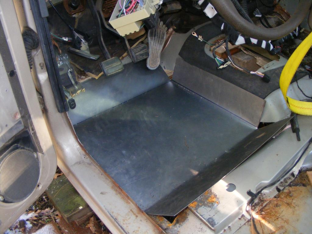
Planning, Bending, and Forming Floor Pan (for the poor idiot who doesn't care how it looks)
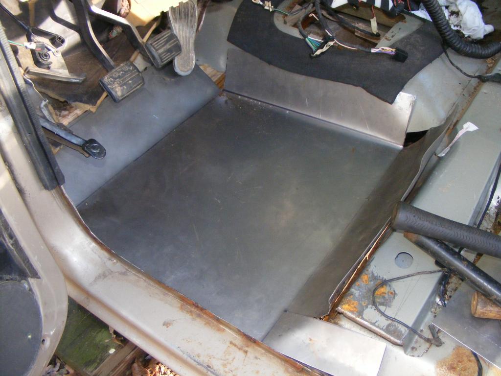
The driver's side floor was rotted. You might be able to tell from this picture if you look closely.
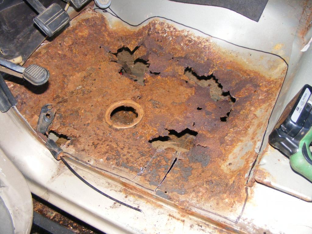
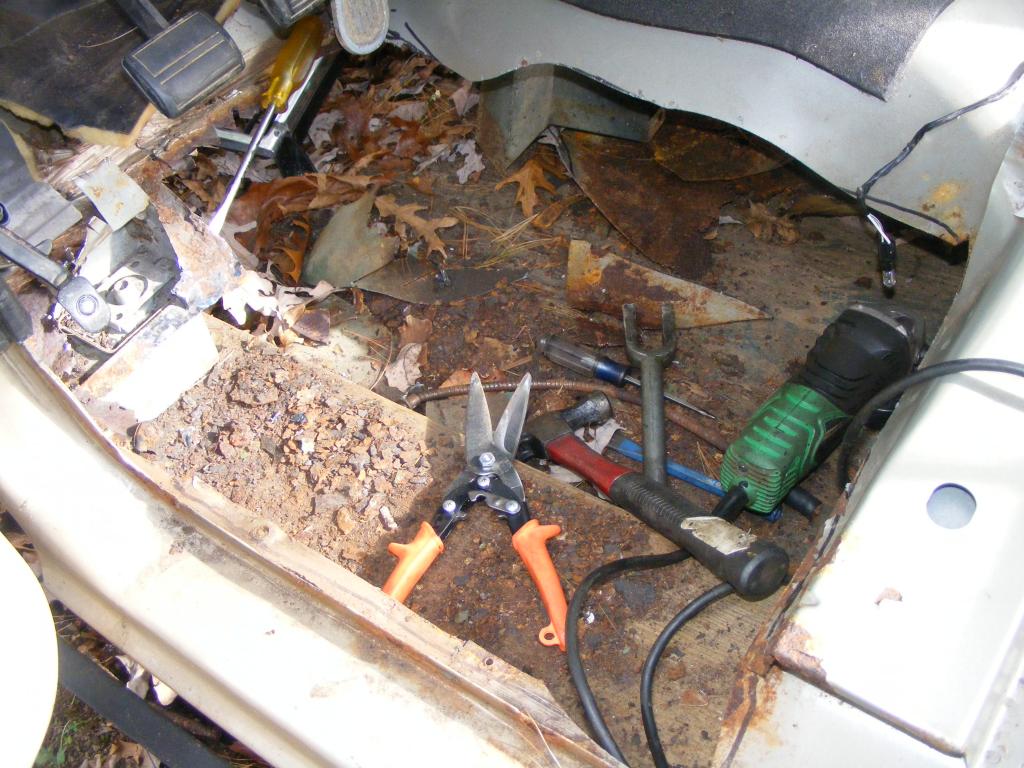
It's all cut/cleaned up and has weld-thru primer on it now.
This is approximately what needs to be replicated in sheet metal form. There are 3 locations that will require patches after the floor is welded in, simply because I can't bend metal how it needs to be bent.
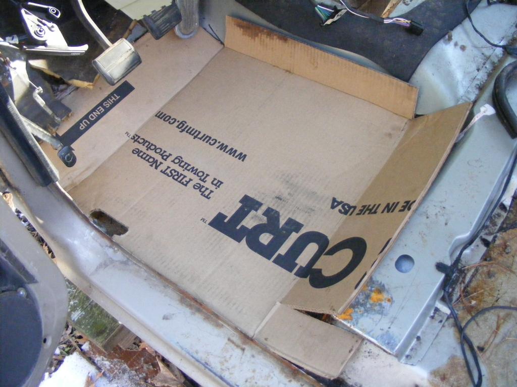
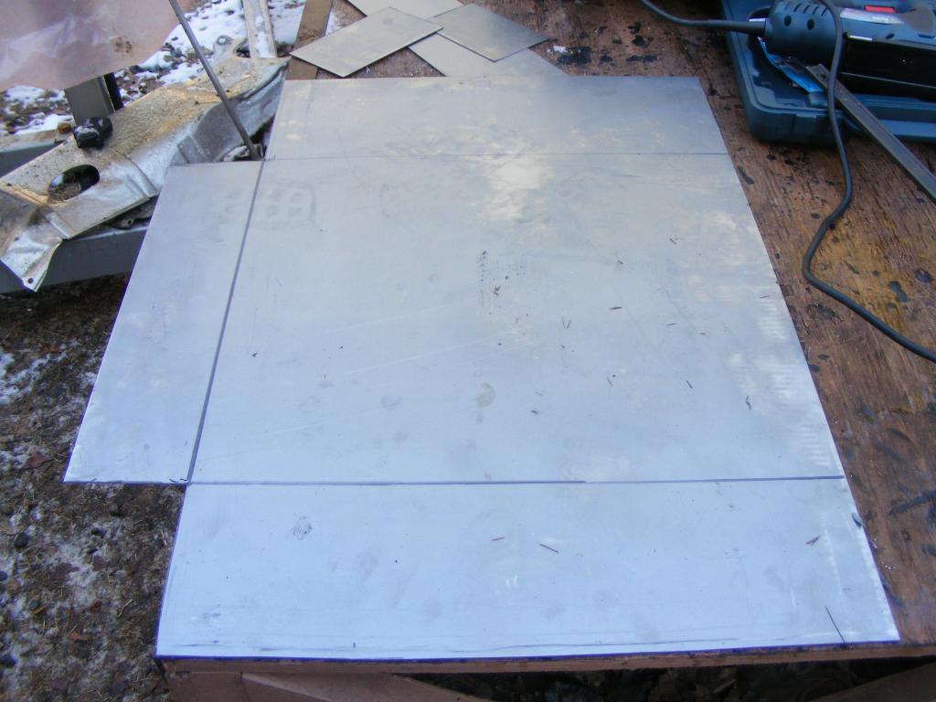
This is a piece of 18 gauge 24"x36" metal. The 24" width is just about perfect, so I only cut the length down.
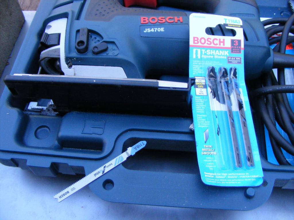
I used a jigsaw with a metal blade to do all the cutting.
After cuts...I've marked where it needs to be bent.
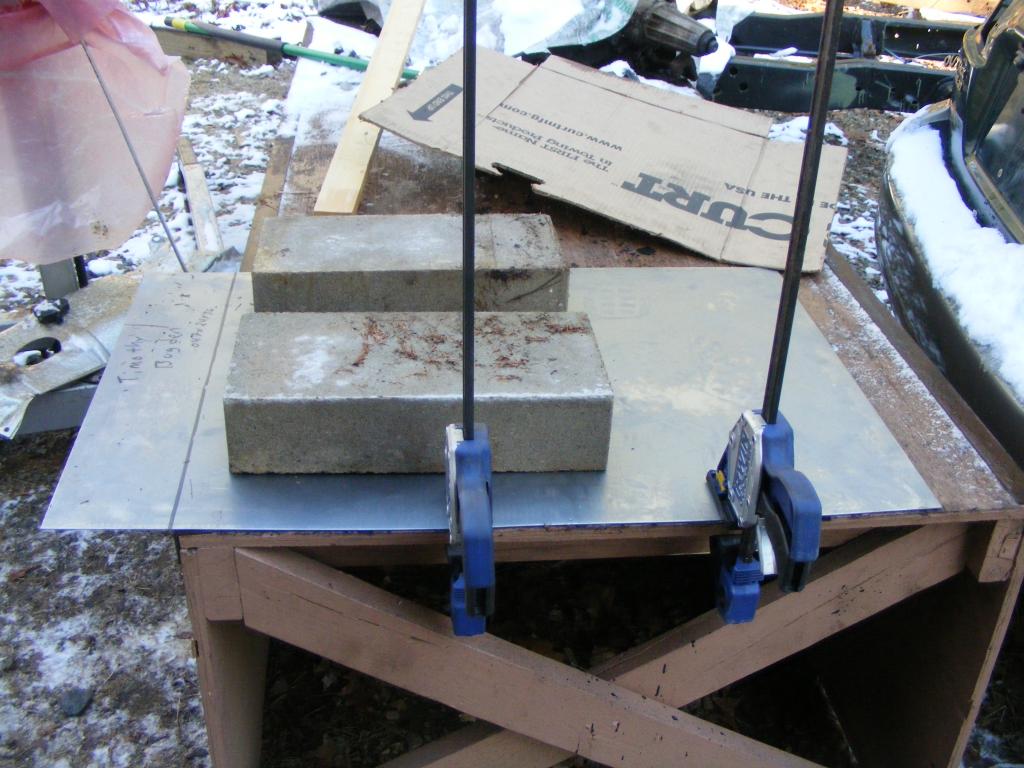
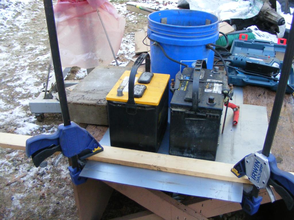
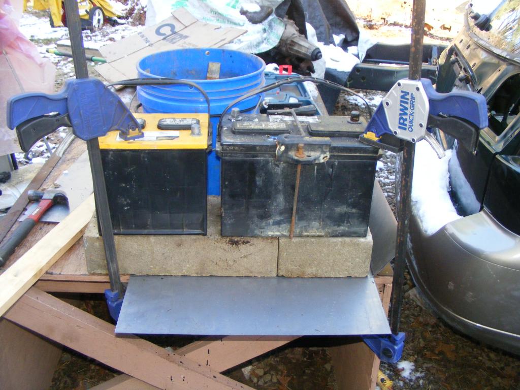
This is how I bent the metal. With respect for actual legitimate sheet metal brakes, I will not call this a sheet metal brake. It's just a thing and it will be referred to as such. I got this idea from hieroglyphics drawn shortly after man first learned how to use tools.
Roughed in.
After a bit of hammering and cutting. Again, there are 3 locations that will require patches after the floor is welded in, simply because I can't bend metal how it needs to be bent...and it's pretty obvious where those locations are.
Rivets will be used at intervals so that the floor is pulled tight against the metal it will be welded to. The holes need to be drilled bigger. I'm going to use 5/16" holes for the plug welds and 1/4" holes for the rivets, only because I have 1/4" pop rivets.
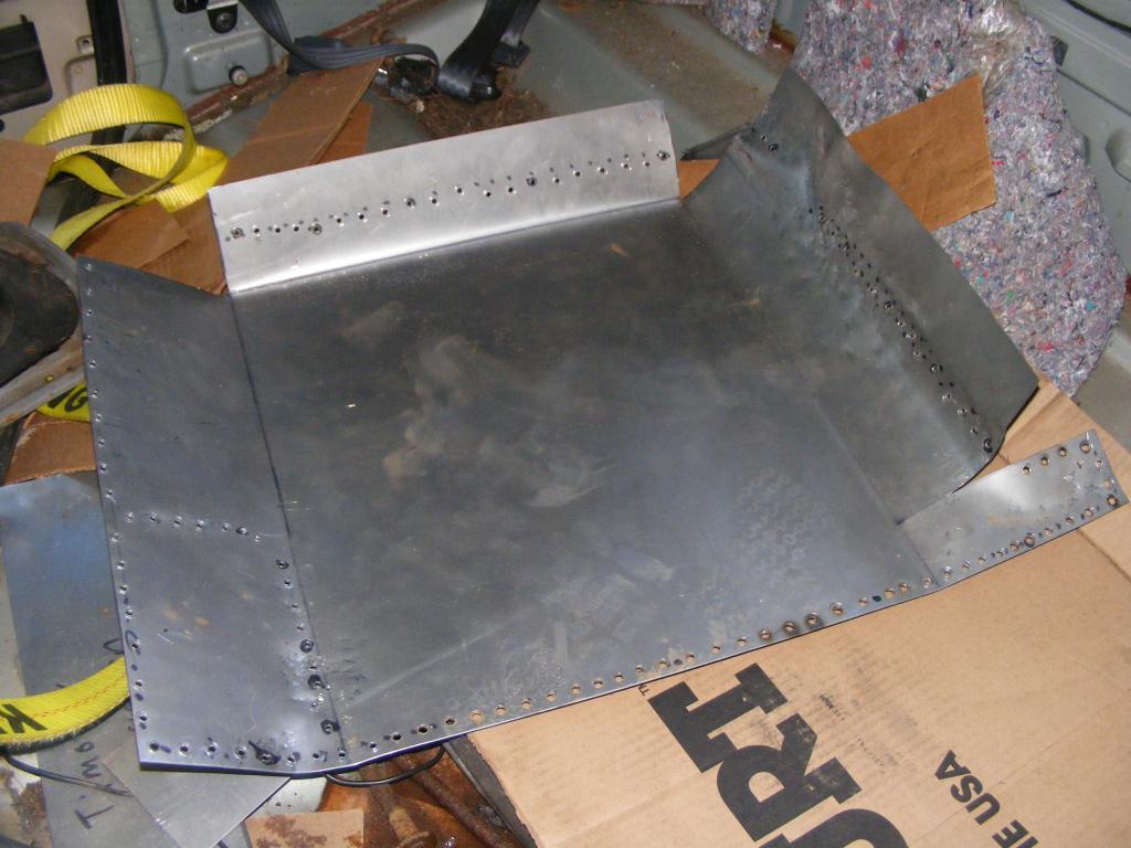
I am extremely happy with how well it fits. It follows the contours on almost all of the floor perfectly. There's only two small places that I can't hammer it enough to contact where it needs to contact but I'll deal with that.
The driver's side floor was rotted. You might be able to tell from this picture if you look closely.


It's all cut/cleaned up and has weld-thru primer on it now.
This is approximately what needs to be replicated in sheet metal form. There are 3 locations that will require patches after the floor is welded in, simply because I can't bend metal how it needs to be bent.

This is a piece of 18 gauge 24"x36" metal. The 24" width is just about perfect, so I only cut the length down.

I used a jigsaw with a metal blade to do all the cutting.

After cuts...I've marked where it needs to be bent.

This is how I bent the metal. With respect for actual legitimate sheet metal brakes, I will not call this a sheet metal brake. It's just a thing and it will be referred to as such. I got this idea from hieroglyphics drawn shortly after man first learned how to use tools.


Roughed in.

After a bit of hammering and cutting. Again, there are 3 locations that will require patches after the floor is welded in, simply because I can't bend metal how it needs to be bent...and it's pretty obvious where those locations are.

Rivets will be used at intervals so that the floor is pulled tight against the metal it will be welded to. The holes need to be drilled bigger. I'm going to use 5/16" holes for the plug welds and 1/4" holes for the rivets, only because I have 1/4" pop rivets.

I am extremely happy with how well it fits. It follows the contours on almost all of the floor perfectly. There's only two small places that I can't hammer it enough to contact where it needs to contact but I'll deal with that.
Last edited by tbugden; Jul 26, 2016 at 09:20 PM.
Thread Starter
|
All Star
Joined: Apr 2013
Posts: 941
Likes: 22
From: Connecticut
This is the current state of affairs in my yard.

Last edited by tbugden; Dec 15, 2014 at 05:54 PM.

All Star
Joined: Mar 2012
Posts: 752
Likes: 2
From: Southeastern Virginia
Dang good work Tbug. You've really covered a lot of territory in a short time, and I'd say you're really getting the hang of the welding thing. That thin floor board metal ought to be fun. What kind of welding gear are you using?
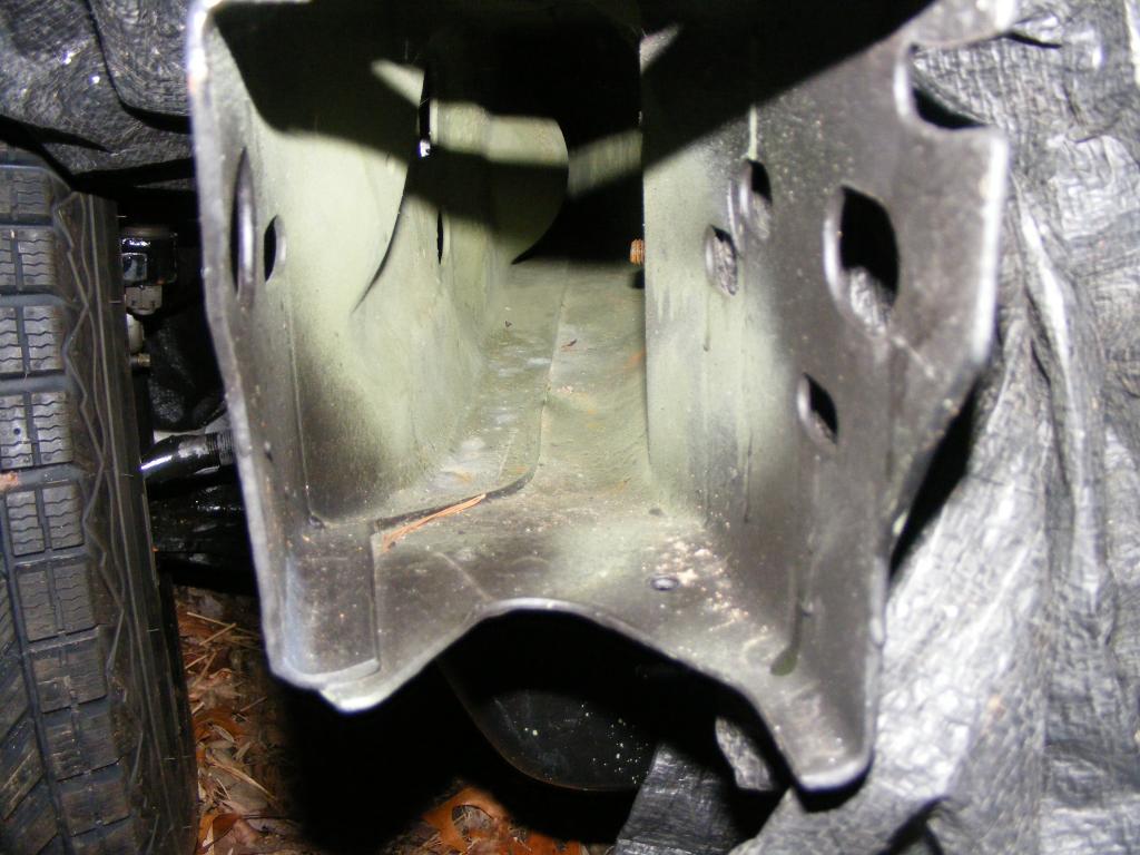
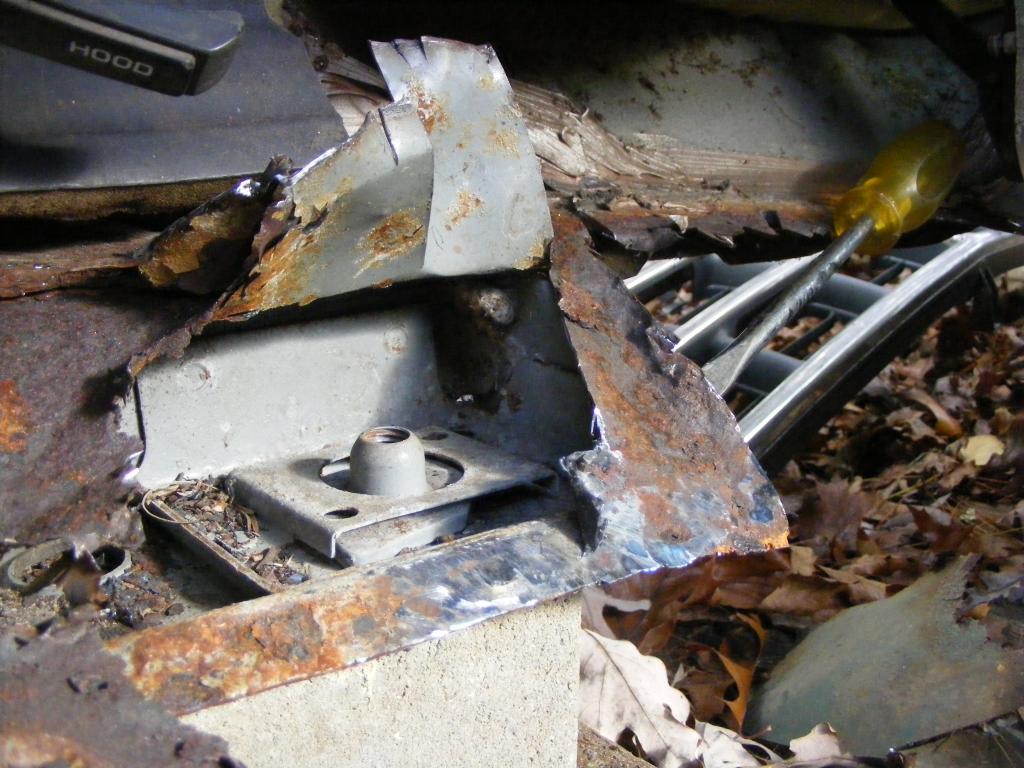
In the picture that shows the cab mounting point at the corner of the driver's side floor plan, it looks like that mount's support was largely provided by the floor pan area. If so, did that mount collapse at all, as a result of the floor board rot? Also, do you think anything needs to be done to bolster that area, as part of your repairs?
Thanks much for posting those pictures of the inside of the cab mount. Now I can clearly see how the capture nut is shaped and how it fits into it's bracket.
Thread Starter
|
All Star
Joined: Apr 2013
Posts: 941
Likes: 22
From: Connecticut
Dang good work Tbug. You've really covered a lot of territory in a short time, and I'd say you're really getting the hang of the welding thing. That thin floor board metal ought to be fun. What kind of welding gear are you using?
In the picture that shows the cab mounting point at the corner of the driver's side floor plan, it looks like that mount's support was largely provided by the floor pan area. If so, did that mount collapse at all, as a result of the floor board rot? Also, do you think anything needs to be done to bolster that area, as part of your repairs?
Thanks much for posting those pictures of the inside of the cab mount. Now I can clearly see how the capture nut is shaped and how it fits into it's bracket.
I've got a Hobart Handler 210MVP. I've only got it hooked up to a 110 right now as I haven't purchased a 220V cable (have plenty of outlets in my house though). Also I'm still using flux core. At this point I don't really see the need to go to MIG w/gas for me, as the welder handles the flux core brilliantly and there isn't much spatter. For the picture of my new tranny mount above, the only thing I did was clean up the welds with a wire brush on a drill. So I would say the thing welds great. My skills are definitely the limiting factor; but I can say that this welder is really damn easy to use. It's also the only welder I've ever used. I am still an absolute novice, but the learning curve seems to be less steep than I anticipated. Oh, and I will be sure to practice some plug welds on 18gauge before going at my floor to find the right settings and get the right technique.
Ragged, you're probably not going to believe me here...but I don't think the cab mount is supported much by the floor. I see no signs of it having bent in any direction neither before I cut the floor out, nor after I've removed all the floor. I know what it looks like, but I think the vast majority of the weight is carried by the attachment points at the front and side of the cab. Of course, I wouldn't say that the floor does nothing structural for the mount, but I think it provides only a relatively small percentage of the mount's integrity. That's my honest opinion. I promise I'm not lying to myself to try to convince myself that the mount isn't fubar (
)...really it seems absolutely fine.I might however do some work to where the floor is supposed to be welded to the mount. The tab on the mount that runs horizontal is one of the two places where there is a gap and I can't get my new floor to contact the tab. The old floor was simply bent/stamped in a way that I cannot duplicate. So I will likely end up shimming the space between that tab or something. Not sure yet. I'm not going to do any extra bolstering though...the floor will be welded to the tabs that it was originally welded to, and I think that will provide at least as much support as the original floor provided.
Last edited by tbugden; Dec 16, 2014 at 12:06 AM.
