

snowboundrmk's 360 build

Thread Starter
|
All Star
Joined: Mar 2013
Posts: 835
Likes: 2
From: Fargo, ND
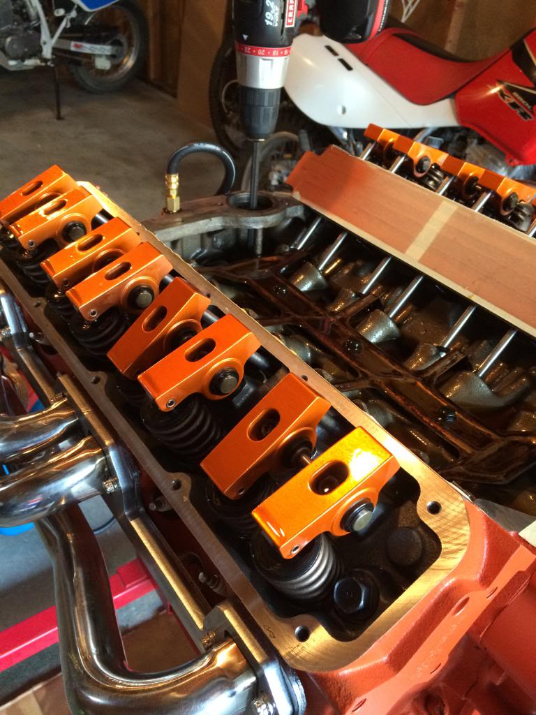
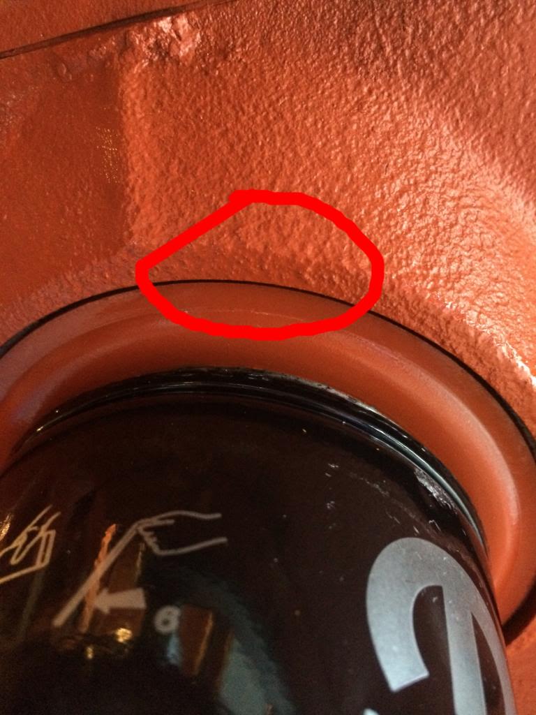
I got my rockers and put them on. I filled the engine with oil and primed it. I think my gauge said like 50-60psi. I didn't have time to pay attention because I had to stop since oil was leaking from between the oil filter adapter and block. I think I'm going to take it off and put some rtv on it. Is that the right thing to do? I googled it and it came up that this was a known issue with the magnums. I circled where I think it was leaking from.


Thread Starter
|
All Star
Joined: Mar 2013
Posts: 835
Likes: 2
From: Fargo, ND
Well I googled it more and it looks like there is supposed to be a gasket in there  . I do remember scrapping off a ton of stuff from that spot though. I though it was just oil sludge. I remember seeing that gasket in my gasket set but I thought it was for in between the throttle body and air cleaner. Haha
Record Breaker
Joined: Mar 2013
Posts: 1,130
Likes: 15
From: Somewhere in Kentucky
I made that mistake before too! I built an engine once, fired it up and oil was shooting out the side from where the oil filter sits. I thought the gasket was for my throttle body. Oops...

Thread Starter
|
All Star
Joined: Mar 2013
Posts: 835
Likes: 2
From: Fargo, ND
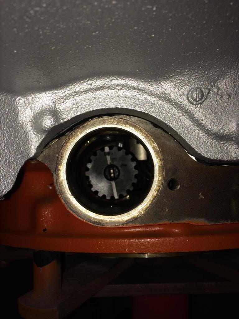
Does this all look right for the distributor. Engine is at #1 cylinder tdc compression stroke. Slot in intermediate shaft points toward left front intake bolt. Rotor points at mark in cam sensor plate.


edit: nevermid, youre good... had to look over my info again. and verify, but yours is fine!
Last edited by redneck_ram; Jun 18, 2014 at 09:10 AM.
Thread Starter
|
All Star
Joined: Mar 2013
Posts: 835
Likes: 2
From: Fargo, ND
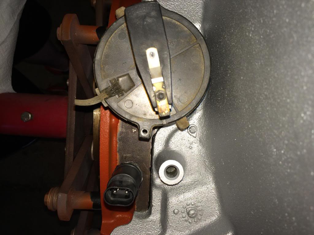
I found a picture from before the motor was apart and I can see how the distributor was. When I put it like in the picture the rotor is a little bit off from the mark on the cam sensor plate. I think the comp cam is advanced a few degrees over stock so that might be why. So should i set it so the rotor is lined up with the mark like in my picture, or how it was stock and have the rotor off a little?
I found a picture from before the motor was apart and I can see how the distributor was. When I put it like in the picture the rotor is a little bit off from the mark on the cam sensor plate. I think the comp cam is advanced a few degrees over stock so that might be why. So should i set it so the rotor is lined up with the mark like in my picture, or how it was stock and have the rotor off a little?