

Fitting a Five-Speed - NV4500
#21
 12-20-2020, 06:52 AM


I haven't got a whole lot further with this recently...
Too many things to do and the problem areas get left behind. One problem I've been facing has been the need to make a new gearbox mount hoop to hang down from the crossmember which supports the box. Here's the regular setup:
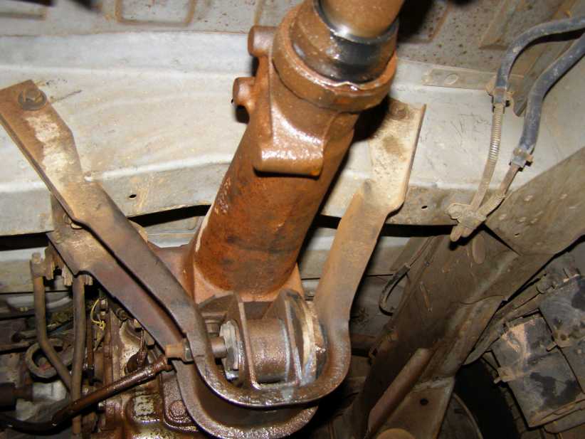
But the NV4500 is wider at this point, this hoop isn't going to work at all. I've recognised this for a while, but it's been a seemingly insurmountable problem because I'd hate to destroy the original hoop (in case I need it some time) but the top ends of it would be difficult to duplicate even if I could make up what I need at the lower end.
For some time I've had two pickups for sale. A man saw them two years ago and told me he'd be in touch, now he's got back to me (after having lost my phone number) and we did a deal. "I have a couple of vans like yours, would you trade them?" he asked. My ears pricked up, there are none of these vans in Australia. Well, maybe half a dozen of them. "They're very rusty and I chopped the bodies off them," he continued. I told him I'd have to have a look at them.
So I went to his place and had a look. They were the earlier model vans, but the gearbox mount and crossmember were the same, so once I did the deal these bits were available to me to use. Hoops to cut up and modify, crossmembers to bolt them to while fabricating the new lower sections.
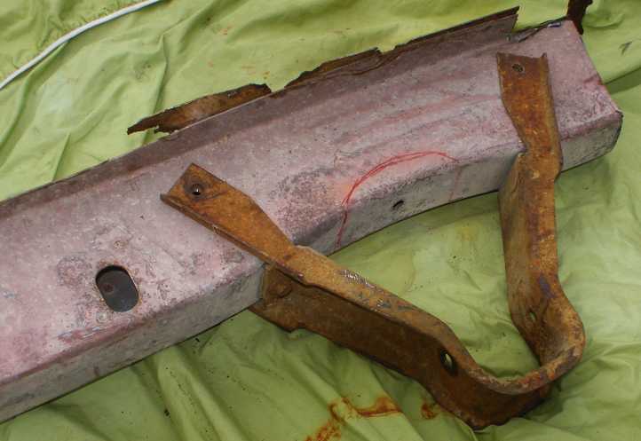
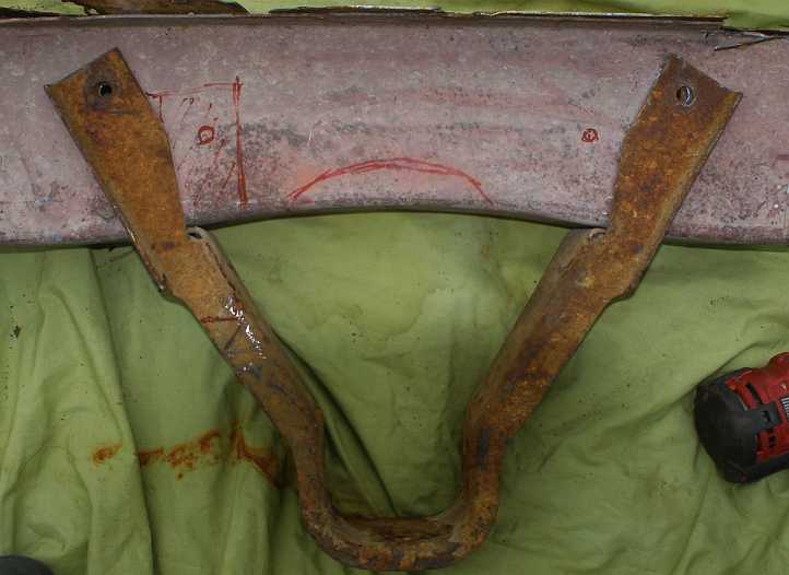
The red marks are the modifications that I plan to make. The centre of the crossmember has to be relieved to clear the top of the new gearbox, it's an inch higher than the original at that point. And because the gearbox is 35% heavier I want to boost the bolt fixings by adding an extra one each side on the front and rear of the crossmember, one being drawn in. And because the gearbox is wider at that point the whole lower section has to be remade. But there's more...
This section in red has to be cut out to clear the 5th gear housing. Obviously it will not just be cut out, new ribbing will be added. And because the gearbox mount itself is further back there will be an addition about the same size to the other side of the hoop. This actually means that the rear of the hoop will be carrying most of the load, so additional bolts are called for and I'll be putting some strap inside both sides of the crossmember, along with some through-bolts and ferrules, to give it more strength.
It's getting pretty complicated!
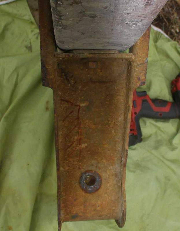
In the meantime, I've removed the 360s and 727s and Dana rears and one steering box from these relics for future reference:
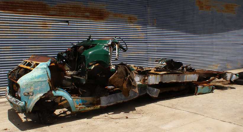
The remains await carting away for scrap.
Too many things to do and the problem areas get left behind. One problem I've been facing has been the need to make a new gearbox mount hoop to hang down from the crossmember which supports the box. Here's the regular setup:
But the NV4500 is wider at this point, this hoop isn't going to work at all. I've recognised this for a while, but it's been a seemingly insurmountable problem because I'd hate to destroy the original hoop (in case I need it some time) but the top ends of it would be difficult to duplicate even if I could make up what I need at the lower end.
For some time I've had two pickups for sale. A man saw them two years ago and told me he'd be in touch, now he's got back to me (after having lost my phone number) and we did a deal. "I have a couple of vans like yours, would you trade them?" he asked. My ears pricked up, there are none of these vans in Australia. Well, maybe half a dozen of them. "They're very rusty and I chopped the bodies off them," he continued. I told him I'd have to have a look at them.
So I went to his place and had a look. They were the earlier model vans, but the gearbox mount and crossmember were the same, so once I did the deal these bits were available to me to use. Hoops to cut up and modify, crossmembers to bolt them to while fabricating the new lower sections.
The red marks are the modifications that I plan to make. The centre of the crossmember has to be relieved to clear the top of the new gearbox, it's an inch higher than the original at that point. And because the gearbox is 35% heavier I want to boost the bolt fixings by adding an extra one each side on the front and rear of the crossmember, one being drawn in. And because the gearbox is wider at that point the whole lower section has to be remade. But there's more...
This section in red has to be cut out to clear the 5th gear housing. Obviously it will not just be cut out, new ribbing will be added. And because the gearbox mount itself is further back there will be an addition about the same size to the other side of the hoop. This actually means that the rear of the hoop will be carrying most of the load, so additional bolts are called for and I'll be putting some strap inside both sides of the crossmember, along with some through-bolts and ferrules, to give it more strength.
It's getting pretty complicated!
In the meantime, I've removed the 360s and 727s and Dana rears and one steering box from these relics for future reference:
The remains await carting away for scrap.
#22
12-20-2020, 07:36 AM

Professional
#23
12-20-2020, 06:15 PM
Mine may well finish up looking a bit like that, however, I'm intent on keeping the original mounting points and their method of attachment.
I do intend adding an extra link to it, however. It has to be a workmanlike job, the crossmember is 16SWG material (zinc plated, I think) with the captive nuts attached to pieces which are formed to conform to the shallow 'V' shape of the crossmember. It's about half an inch wider at the top than the bottom.
I have to cut that slice out of the lower section at the middle, so I can put some fresh things in there for additional mounting - but I'm also looking at the strengthening.
Sometimes I go to a whole lot of effort to do things...
#24
12-21-2020, 10:41 AM
Mine may well finish up looking a bit like that, however, I'm intent on keeping the original mounting points and their method of attachment.
I do intend adding an extra link to it, however. It has to be a workmanlike job, the crossmember is 16SWG material (zinc plated, I think) with the captive nuts attached to pieces which are formed to conform to the shallow 'V' shape of the crossmember. It's about half an inch wider at the top than the bottom.
I have to cut that slice out of the lower section at the middle, so I can put some fresh things in there for additional mounting - but I'm also looking at the strengthening.
Sometimes I go to a whole lot of effort to do things...
I do intend adding an extra link to it, however. It has to be a workmanlike job, the crossmember is 16SWG material (zinc plated, I think) with the captive nuts attached to pieces which are formed to conform to the shallow 'V' shape of the crossmember. It's about half an inch wider at the top than the bottom.
I have to cut that slice out of the lower section at the middle, so I can put some fresh things in there for additional mounting - but I'm also looking at the strengthening.
Sometimes I go to a whole lot of effort to do things...

#25
12-21-2020, 09:52 PM
Especially seeing as one day I might need to OVERwork it...
I do think the crossmember is getting on towards its limits with this weight. The engine mounts are way forward, the gearbox mount right near the back, so half the weight between Nos 3 & 4 cylinder and the back of the gearbox, not to mention the front half of the driveshaft, is hanging on there.
Then add the complication of a worn front universal shaking things to bits.
#26
04-26-2021, 11:20 AM
I've been steadily working away on things...
A major interruption to all of this has been the need to prepare a Ford Territory to do pilot/escort work, which will become my income mainstay in the near future. Doing all the electrical work on that and overcoming Ford's useless (should I say 'dangerous'?) roof rail attachments took up a lot of my time. I will also set up the van to do this work, so I have made all the electrical gear portable so I can just take it from vehicle to vehicle.
I have now made up two braces to go within the crossmember with a whole lot of captive nuts that will enable me to increase the number of bolts retaining the new gearbox mounting frame and also provide a very secure pair of braces across the section of the crossmember I have to relieve to clear the back of the gearbox. I've also been working on that bell crank for the clutch and I've been machining a whole new setup to replace that which uses Acetal as a bush and is both larger diameter and longer to eliminate the lost motion I was seeing in this area of the clutch linkage.
Photos will follow as I actually get on with the fitment of these things. The gearbox mount which was supplied when I bought the gearbox still needs to have some brackets made to attach it, but it's a handsome mount and will do the job nicely:
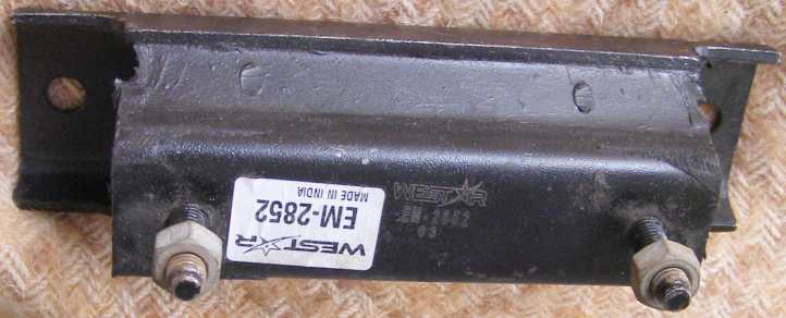
Ultimately I plan to use one of the Dana 60 rear ends in my van, too. These were fitted to the earlier model and I have two from the wrecks. Unfortunately only one of the four brake drums was not rusted to the brake shoes and it took a bit of effort to get the one on the other end off:
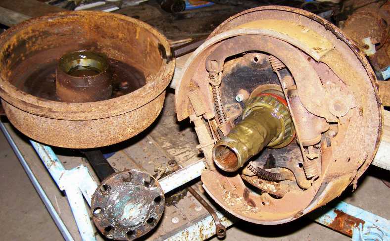
One brake shoe was bent up a bit in this process. These are the same, dimensionally, as the 9� rear end I have, same ratio, same brake size, but I have a Power-Lok on hand which I can instal and which will come in handy.
Slow progress, I know, but as I do a little bit every day I feel that I'm getting closer to fitting day all the time. I also mounted a piece of very rusty drag link from one of those wrecked vans in the lathe today. It became a clutch alignment tool to suit the 19-spline clutch plate I needed. I don't think I mentioned that my time on the lathe at the Men's Shed has also yielded some offset dowels for the bellhousing.
A major interruption to all of this has been the need to prepare a Ford Territory to do pilot/escort work, which will become my income mainstay in the near future. Doing all the electrical work on that and overcoming Ford's useless (should I say 'dangerous'?) roof rail attachments took up a lot of my time. I will also set up the van to do this work, so I have made all the electrical gear portable so I can just take it from vehicle to vehicle.
I have now made up two braces to go within the crossmember with a whole lot of captive nuts that will enable me to increase the number of bolts retaining the new gearbox mounting frame and also provide a very secure pair of braces across the section of the crossmember I have to relieve to clear the back of the gearbox. I've also been working on that bell crank for the clutch and I've been machining a whole new setup to replace that which uses Acetal as a bush and is both larger diameter and longer to eliminate the lost motion I was seeing in this area of the clutch linkage.
Photos will follow as I actually get on with the fitment of these things. The gearbox mount which was supplied when I bought the gearbox still needs to have some brackets made to attach it, but it's a handsome mount and will do the job nicely:
Ultimately I plan to use one of the Dana 60 rear ends in my van, too. These were fitted to the earlier model and I have two from the wrecks. Unfortunately only one of the four brake drums was not rusted to the brake shoes and it took a bit of effort to get the one on the other end off:
One brake shoe was bent up a bit in this process. These are the same, dimensionally, as the 9� rear end I have, same ratio, same brake size, but I have a Power-Lok on hand which I can instal and which will come in handy.
Slow progress, I know, but as I do a little bit every day I feel that I'm getting closer to fitting day all the time. I also mounted a piece of very rusty drag link from one of those wrecked vans in the lathe today. It became a clutch alignment tool to suit the 19-spline clutch plate I needed. I don't think I mentioned that my time on the lathe at the Men's Shed has also yielded some offset dowels for the bellhousing.
#27
05-17-2021, 11:58 PM
Here's something I found I had to do with this installation, completed a long time ago:
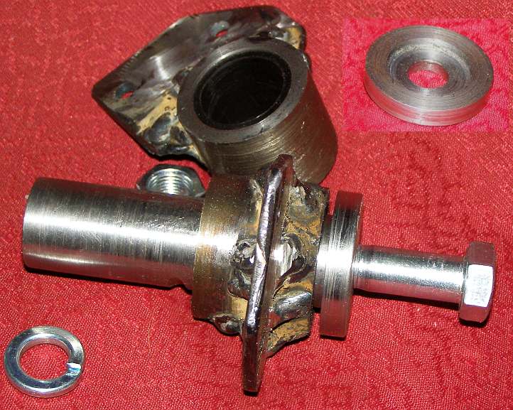
Because the spigot shaft is shorter than the A833, I machined up this spacer to press into the back of the crank. I may use something like Loctite to hold it in, but it will also be a neat fit for the spigot bush itself. For that I went out and bought a 3" long piece of bronze bush of the right dimensions and I've cut it to length, so it goes into this spacer and also into the crank.
More recently I've made up a whole new bell-crank arrangement to get rid of the steel-on-steel (and very worn out) original. I've used a bush made from Acetal (or Delrin) and machined up pieces to make the whole thing larger, it was just as easy to make two while I was at it in case I mucked up somewhere at the last minute:
And here it is in a 'trial assembly' mode, the lever part still to be bolted to the core:
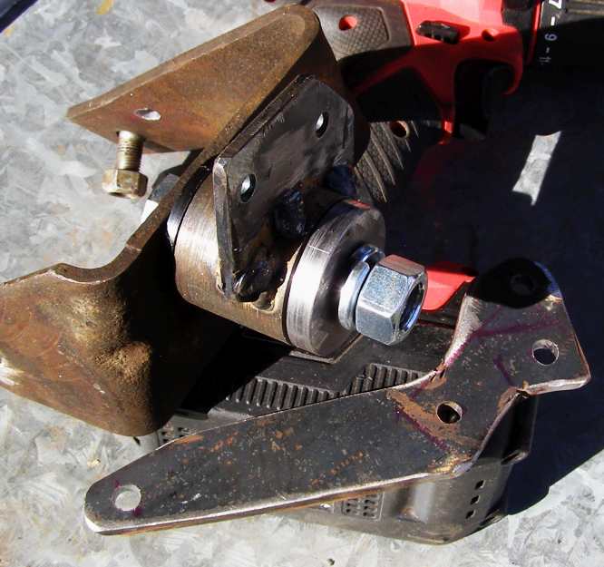
Note that there's a second hole in the rear leg of the mount... this is on the vehicle chassis, but not on the mount, so I've drilled it and will fit a bolt as I found that the mount was twisting on the chassis as it was. And by welding a tab between the heads of the bolts it will finish up easier to bolt in place. Anyone who's worked on this area will know what I mean.
Because the spigot shaft is shorter than the A833, I machined up this spacer to press into the back of the crank. I may use something like Loctite to hold it in, but it will also be a neat fit for the spigot bush itself. For that I went out and bought a 3" long piece of bronze bush of the right dimensions and I've cut it to length, so it goes into this spacer and also into the crank.
More recently I've made up a whole new bell-crank arrangement to get rid of the steel-on-steel (and very worn out) original. I've used a bush made from Acetal (or Delrin) and machined up pieces to make the whole thing larger, it was just as easy to make two while I was at it in case I mucked up somewhere at the last minute:
And here it is in a 'trial assembly' mode, the lever part still to be bolted to the core:
Note that there's a second hole in the rear leg of the mount... this is on the vehicle chassis, but not on the mount, so I've drilled it and will fit a bolt as I found that the mount was twisting on the chassis as it was. And by welding a tab between the heads of the bolts it will finish up easier to bolt in place. Anyone who's worked on this area will know what I mean.
#28
01-28-2023, 08:31 AM
It's about time I gave an update here...
Especially since I've actually taken out the A833 and been working on aligning the bellhousing for the NV4500.
The latest pics of the bell-crank shows that it's all ready to go:
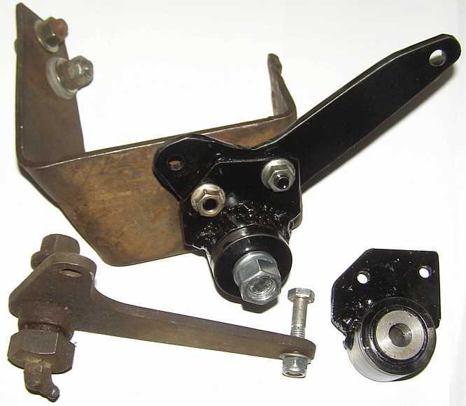
I really should explain that the central piece is drilled out for the �" UNF bolt for most of its length, then tapped at the outer end so that the bolt directly retains this securely against the bracket. The rest of the components are then assembled and held in place by the outer cap which is retained by the nut and spring washer. Having made two of each component for the core of this I have a spare on hand in case anything goes wrong.
The clutch alignment tool is machined to the ID of the 19-spline drive of the clutch plate:
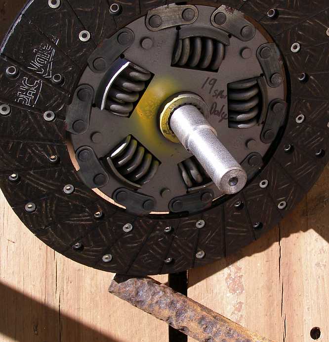
The rusty drag link from whence it came is seen below it.
As the clutch plate supplied was too big in diameter I had to get that changed. No such thing as 19-spline clutch plates in Australia in any size, but I found among my new 10�" clutch plates there was one with the same rivet pattern as the 11" plate. I have a good contact who plays with clutches and he took care of swapping it over:
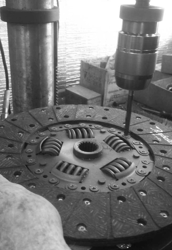
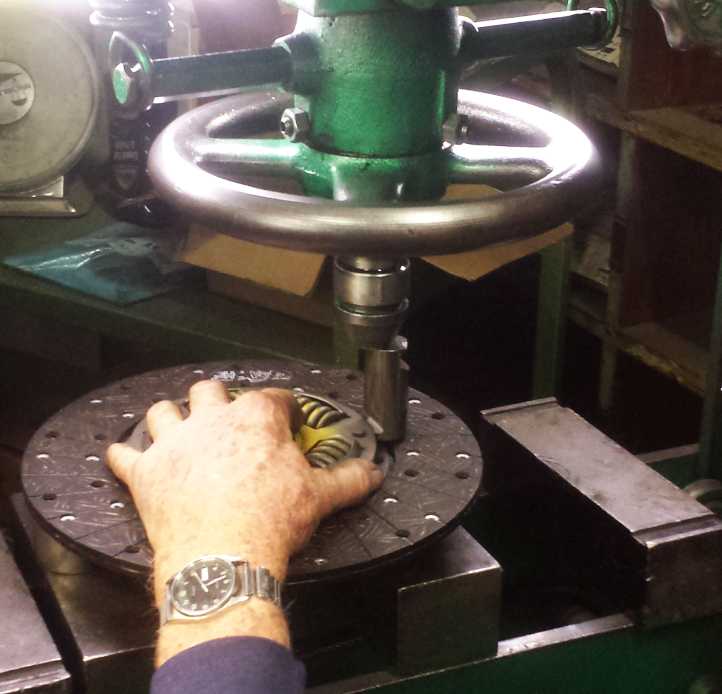
And so the rivets were drilled out, new ones pressed in and the swap made - all very professional like.
There is more, I'll have to catch up with all of this soon.
Especially since I've actually taken out the A833 and been working on aligning the bellhousing for the NV4500.
The latest pics of the bell-crank shows that it's all ready to go:
I really should explain that the central piece is drilled out for the �" UNF bolt for most of its length, then tapped at the outer end so that the bolt directly retains this securely against the bracket. The rest of the components are then assembled and held in place by the outer cap which is retained by the nut and spring washer. Having made two of each component for the core of this I have a spare on hand in case anything goes wrong.
The clutch alignment tool is machined to the ID of the 19-spline drive of the clutch plate:
The rusty drag link from whence it came is seen below it.
As the clutch plate supplied was too big in diameter I had to get that changed. No such thing as 19-spline clutch plates in Australia in any size, but I found among my new 10�" clutch plates there was one with the same rivet pattern as the 11" plate. I have a good contact who plays with clutches and he took care of swapping it over:
And so the rivets were drilled out, new ones pressed in and the swap made - all very professional like.
There is more, I'll have to catch up with all of this soon.
#29
03-21-2023, 06:36 PM
Now I've come up against a real problem!
I should have checked, I should have realised earlier, my new bellhousing is for the larger flywheel, not the 130-tooth that I've been running. I do have a flywheel to suit except that it hasn't been balanced (either drilled or had weight added) for the 360's external balance needs.
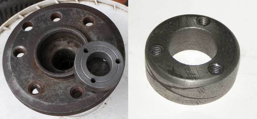
I know the pattern that most are drilled to, three 1 13/64" holes at set distance and in a set location on the flywheel, but the difficulty of getting that size drill daunts me and apart from that, my existing flywheel was drilled to a different pattern altogether:
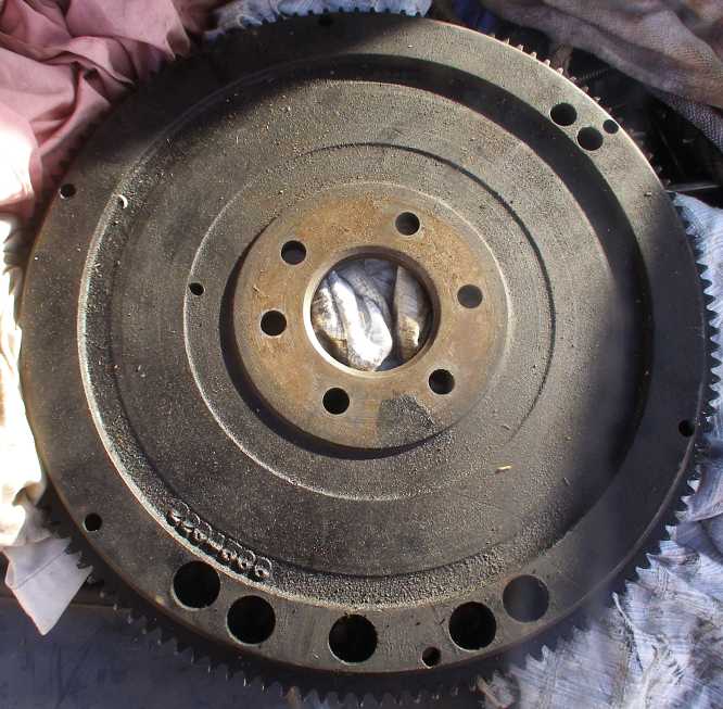
This was done for me in Spokane when I fitted the A833, the people who did it said that it was a pattern used on some different flywheels from the factory. The holes are 0.75" in diameter and 0.6" deep, while they are further outboard than the other pattern, being about 5.4" from the flywheel centre. I'm sure it worked fine, but what I'd like to know is whether or not there is a drawing or description anywhere of this so I can duplicate it into the bigger flywheel.
Can anyone help with this?
I should have checked, I should have realised earlier, my new bellhousing is for the larger flywheel, not the 130-tooth that I've been running. I do have a flywheel to suit except that it hasn't been balanced (either drilled or had weight added) for the 360's external balance needs.
I know the pattern that most are drilled to, three 1 13/64" holes at set distance and in a set location on the flywheel, but the difficulty of getting that size drill daunts me and apart from that, my existing flywheel was drilled to a different pattern altogether:
This was done for me in Spokane when I fitted the A833, the people who did it said that it was a pattern used on some different flywheels from the factory. The holes are 0.75" in diameter and 0.6" deep, while they are further outboard than the other pattern, being about 5.4" from the flywheel centre. I'm sure it worked fine, but what I'd like to know is whether or not there is a drawing or description anywhere of this so I can duplicate it into the bigger flywheel.
Can anyone help with this?
#30
03-21-2023, 07:20 PM