When you click on links to various merchants on this site and make a purchase, this can result in this site earning a commission. Affiliate programs and affiliations include, but are not limited to, the eBay Partner Network.
oh, hell I have 3 people locally that can TIG aluminum all day long. One already volunteered to weld the timing cover for me.
I haven't found any hard data that I need for the water pump situation. But it's a single in/single out. I have to figure out if I want to Y it out and have a bung in front of each opening to the block, or just have one hose come in the center of the plate. I know the former is more popular, but i'm not sure how the water reacts with the big void in the middle where the impeller would normally be.
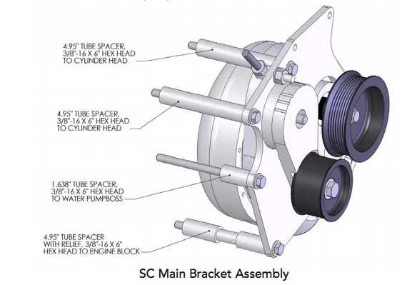
Found a couple pics of the procharger 7.65" 12 rib crank pulley. Looks like it should work just fine with the mendrel plate I made.
Ordered the LT1 blower pulley from TRE Performance. Should have dropshipped from ATI on Friday, should be here Wednesday or Thursday. The photos above show it as being a 6 bolt, but TRE/PC claims it's 3 on 3.2". Either way, I'm going to bolt it to the GM pattern on my mandrel plate, then drill the pulley for the chrysler pattern...if there's room for it. If not, then I'll have to do some voodoo.
Nick North at TRE says that I'll be better off with an F1A, good for around 1100 HP off a 400HP NA baseline. He also mentioned that the F1A-94 is a slightly newer and more efficient design good for 1300 HP. Key thing for me is "more efficient". Less drag to make the same boost means more power, right?
This build over on LS1 tech is absolute eye candy. Much nicer than what I'm putting together. But it's also giving me ideas on how I'll package the blower in - our trucks have ALOT more room than a little F body...I would know since I can put both platforms next to eachother in the driveway. haha. My idea is to mount the blower up high above the exhaust manifold - about where the stock power steering pump used to be. It should put the air filter somewhere around the master cylinder, then blow down into the A2A in the lower bumper, then come back up the passenger side. Probably use a 3/8" laser cut steel plate for the mounting plate off the block (since 3/8" spacers are what made the power steering pump fit perfectly) using the 2 bolts in the head and the 2 bolts for the LA style motor mounts. That will give 4 bolts holding the steel plate on, then I can mount the aluminum plate and blower to that plate, with extra straps going to the timing cover/accessory bracket.
I also like the hopes I am given in that he's only using one plate of 1/2" 6061T6 aluminum. Most installs I see use two 1/2" plates with spacers between them.
With that said, an F1R on a 383" LT1 isn't a far baseline from a 408" magnum. But I'm sure the aluminum LT1 heads are tons better than any iron head you can get for a magnum. I have EQ 1.92's to put on, would be nice to have 2.02's, but I got what I got.
With the timing over clearanced for the ATI balance,r i took it to a friend to weld it up. As usual, the cast aluminum was no weld-friendly, and even when cleaned, still had alot of impregnated oil and contaminents that made it hard to carry a puddle. It's not pretty, but it shouldn't leak. The front side definitely shows where the heat came through. I figure I can pack the front opening with RTV to help co-seal it in the event that one of the contaminent micro-bubbles does have a connecting pinhole to the outside.
I also got the procharger pulley in, it's for an LT1 4th gen F-body as shown in some of the previous photos i took from an F-body forum. It uses a 3 on 3.2" bolt pattern, one hole is slotted for either the standard SBC/BBC pattern or the LT/LS pattern which has one bolt offset 5 degrees. The trick was that I was expecting 3/8" holes, and it's actually 7/16". So I had to drill out my 3/8" steel adapter plate further than I had anticipated. And in doing so, i drilled out 3 holes of the mopar pattern instead of the GM pattern :facepalm: so I had to go back and do the correct 3 holes on the GM pattern. I then took it to a friend's shop and opened up the center hole to match the 2.25" diameter of the pulley's centering lip.
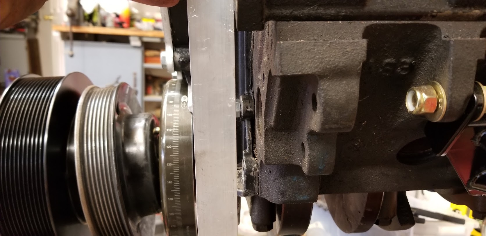
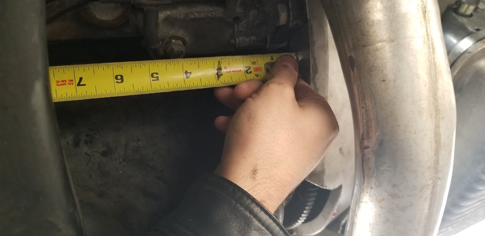
I was going to use an underdrive main pulley, however the shoulder of the P/C pulley will not fit inside the U/D pulley. So i'll have to use the stock main pulley. The P/C pulley is 1.75" wide plus a 1" shoulder. I *could* let it hang out that far, but it would be sketchy. It will be better to have the P/C pulley as far inboard as I can to minimize the side-loading on the crank snout. Stacked tight, it is about 6-3/4" from the face of the PC pulley to the forward lip of the timing cover.
Last edited by magnethead; 01-07-2018 at 06:28 PM.
Doing some more research. Spent a half hour on the phone with procharger tech support today.
F1C-94: Don't use. It's for NMCA/NMRA Mustang class only.
F1R: Don't use. Takes a very large small block to make work properly due to extreme parasitic losses (but will make monster power once you can get it spinning). High IAT's guaranteed due to impeller design.
F1A-94: Could use, but has fairly high parasitic losses, but not as bad as F1R. Very efficient compressor means it tends to have very high IAT's if the intake air is of elevated temperature, such as near exhaust header, even at low boost.
F1A: Best for the situation. A much-updated core from the F1D and F1, but does not compress the air as violently as the A-94 or R and thus does not create as high IAT's for the same boost level.
Procharger also offers "free" mock-up blowers. You give them a deposit of $400 plus $40, they send you an empty gearbox and volute assembly with pulley shaft. You pay another $40 shipping to send it back, and they credit you the $400 back. That's actually one hell of a deal for somebody in my boat.
The tech (Jeremy B) also sent me some information on tensioners. P/C's preferred system for the 8 and 12 rib dedicated systems is a manually located spring tensioner. It allows you to set the tensioner location for a specific belt length configuration, you set it to a specific preload, then the spring takes care of the belt from there. It's the best of both worlds, when used properly and with a brain.
I spent the last 2 days doing a bunch of measuring. It looks like I can mount a 6x12" plate of 3/8" steel to the cylinder head (4 direct 3/8" bolts) and the LA mounting ears (2 7/16" bolts with 1-3/4" spacers of 3/4x0.120 DOM). That will give me mounting surface from the base of the AC compressor to the base of the timing cover (12" tall), and out to the edge of the exhaust manifold (Head ports @ 4", mani stops @ 6").
Mounted directly face-to-face to that 3/8" steel plate, will be a 12" x 12" slab of 1/2" aluminum plate. However, it will have to be offset 1.5" to clear the LS power steering pump retrofit (and may have some other areas relieved for hose clearance). This will give me coverage from 1.5" to 13.5" outward, with the same vertical location of the steel plate. The 13.5" dimension is rather important because that is the location of the inboardmost location of hipotek's PDC mounting brackets. From this plate, there will be at least 1 if not 2 brace anchors going back to Hipotek's poly motor mounts. This will be to keep the 3/8 and 1/2" plate combination from bending.
The second 12x12" slab of 1/2" aluminum will be placed identically to the first, however there will be spacers between them of an arbitrary length. 1/2-20 bolts will go through the front plate, spacer, and either through the second plate and thread into the steel plate, or will thread directly into the second plate where the steel one is not present, with a nylock on the backside. This will absolutely ensure that in no way, shape, fashion, or form will the assembly ever be able to flex out of alignment unless the anchors to the motor mount break.
The front plate will then be notched and the head unit dropped in, idler and tensioner added. Hopefully somewhere along the time, the spacer length will be decided such to make the belt line up with the crank pulley.
Last edited by magnethead; 01-11-2018 at 02:44 AM.
Based on the LS transplant blueprint, the F1X/F2 series of blowers are 10.5" from face of pulley to volute flange, based on a 2" cog belt pulley (dimensionally same as 12 rib), which means the head unit itself is 8.5 inches thick. Seeing as I have 4.5" in front of the cylinder head, that means that the gearbox/volute mating surface will be around the front of the head, and the volute will be above the exhaust manifold. Meanwhile the P1/D1/F1 based kids are 8.75" thick with an 8-rib (1.25") dedicated belt on a 3/4" offset pulley. Either way, I can't fit the whole blower in front of the head, so there will be some space sharing going on. But i knew that.
I'm keeping AC, and going to a half-size radiator to make room for plumbing and the electric water pump. If i go FMIC i'll be blocking off part of an already shrunken radiator, along with the intercooler behind it. I can fit a 10x10 in the end of each bumper, but that's not cost effective. If I remove the sway bar, I can fit a 26x10 laying down but then I run the risk of road debris, parking curbs, ect. I have sent quote requests out for a 27.5 x 13 inch, 3 1-inch-row radiator to 4 different companies. That's basically a Scirocco radiator, but 5.5 inches wider and much thicker. Stock radiator is about 540 square inches, this will be 315 square inches. So the extra surface area of bigger rows and a third row is necessary. The Pierburg CWA200/400 pumps are 8" square x 9 inches long. That will leave me a 20 x 8" or so opening under the radiator next to the water pump, which I can put a 26x10 FMIC in front of, but will require some magical space making. The real trick will be the AC condenser.
With the pierburg pump, tinyCWA controller, 165 thermostat with six 1/8" holes in it, and a decent pair of 10" radiator fans, I shouldn't have too many issues with cooling. The bypass port on the intake will be pipe plugged off and the heater core return hose will tee into the lower radiator hose.
Tuff Paw is making us a new fuel tank for the dragster right now, I am going to ask him about one for the truck if we like what he sends us.
The inside/inside longitudinal dimension of the tire carrier is 19", and it is 32" plus a little between the frame rails. From the tire carrier to the bottom of the hitch is 11.5 inches. I want to re-use the factory fill port, so I will need 2-2.5 inches of height under the bed to run the hose into a fitting. That reduces the tank to about 9 inches tall, 8 inches if he can do a 1" sump. A 17x30x9 tank is 4590CI = 19.8 gallons, 17x30x8 = 4080CI = 17.5 gallons. That would let me use the tire hanger as the primary mount with ties going to the frame rails for support. With the factory fuel tank gone, I can add a front cross member over the axle to run both double adjustable shocks and an anti-roll bar to. I'll also be mounting the new fuel pump and management systems to the driver side frame rail where the old tank was.
From the bellhousing face, the K member starts at 7.5 inches and ends at 16 inches, the front crossmember (not core support, but in front of the sway bar) starts at 26 inches (minus the 1/4" motor plate). Comparatively, the V8 block is 21.5" face to face, 22.5" to the timing cover, and 27.5" to the face of the serpentine crank pulley. This may cause a conflict of space between the blower pulley and the front crossmember, but nothing a grinder and welder can't fix.
I heard back from TCP Performance and griffin radiator today.
Basically I asked for information on building a "wide scirocco" radiator. A regular scirocco is a single 18x12 core measuring 22x13 total. Our radiator opening is 28 inches wide, so I asked for information on having one basically widened 6 inches and in a triple core format, ideally three 1 inch cores.
I also went back and forth with Chiseled Performance about a custom intercooler. Bad news bear, there. I'm not impressed with how he presents himself in language, and I kind of get the feeling that he's not interested in contributing to the project.
Originally Posted by GRIFFIN
Thank you for contacting Griffin about a custom radiator.
3 core refers to a copper brass radiator. We build our radiators with 2 row 1.25” tube and 3” thick tank. You would not want to go thicker than that because it will reduce air flow.
We would be happy to build one for you based on your specs. We need you PRINT out our CUSTOM RADIATOR TEMPLATE and fax it in or scan it and email it to me at mmorgan@griffinrad.com.
Please PRINT IT OUT, fill it out completely, including: Core and tank size (pg1) dimensions, inlet/outlet positions, filler neck, mounting brackets etc. and fax it to my attention at (864) 845-5001 or scan it and email it. My builder will use your drawing so all information needs to be on your drawing.
Custom radiators generally start at $650 and take 2-3 weeks to build. We will know more once we see your particular application.
Originally Posted by TCP
We can build that. A 3 row 1" tube core would put the core at 3.5-3.75 then we need an extra .25 front and back for the tanks making them as deep as 4.25. or you can go with a 2 row 1.5" core that will be 3.25 thick making the tanks 3.75. Inlet and outlet on same side not a problem, we will baffle tank and make it a dual pass design which will enhance it's cooling ability by about 15%.
You would be looking at $825 plus shipping. Core thickness would be 3.5 3 row 1" tubes and the tanks would come out to 4".
Originally Posted by CHISELED(sic)
I would not put two mini coolers, that just going to flow like crap and kill your boost, so 26" from air tube to tube ?, being that all these cores are 24" , that not enough room if going with the 703520-6011, you're kinda limited on space but the nitrous will help with the cooling, we can do the air tubes offset to the btm so the air tanks taper towards the top
>> OK, if they don't have a short core, then 28 can work, I'll just have to use pie cut's for the bends instead of mandrels. "Ugly but functional". Would also like V-band flanges for the connections.
This is the smallest you can make this, you are already small on core size,and air tanks cant be any smaller, can you fit a 4.5" thick core, and 12" tall?
>>4.5 thick won't package well, and would rather not do 12" tall :/
Looking back at some of my old posts and double checking the cylinder head pattern so I know where to start with drilling the 3/8" steel blower plate. Given how much cylinder head gaskets can change things, I'm just going to make the primary hole, mark the head with transfer material, clamp the plate on, drill the other 3 holes, put the plate back on, mark the 2 motor mount holes, then move them down .035 to account for a 30-40 head gasket.
I used my set of calipers to measure far-far and close-close to get the numbers shown below. The actual values are 2.450, 3.020, and 3.200 ; I rounded them to the nearest fractional since I would like to assume that's what the pattern is actually drawn on. Obviously using the transfer method will work best when I get that far. That said, precision would be nice, but with 6 anchor points plus extra straps going different places for reinforcement, I think having the plate holes a couple thou or a hund big will be fine. Obviously the starting hole will be drilled pretty exact.
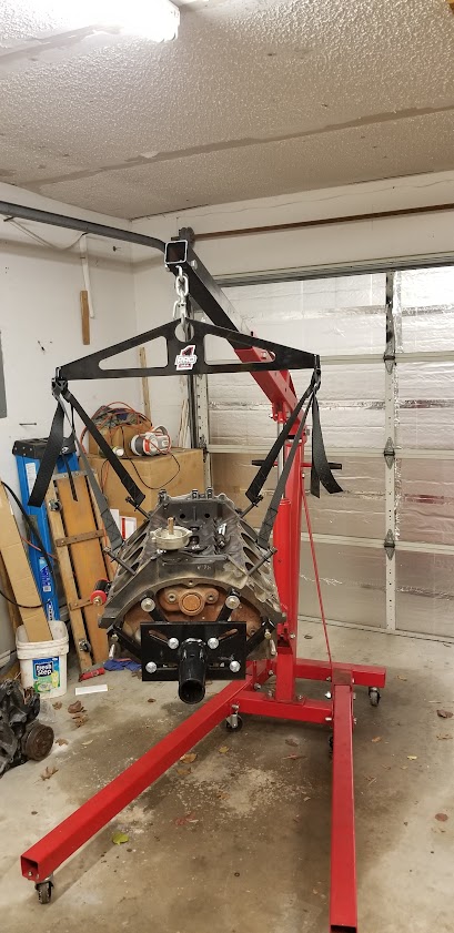
I also pulled my block off dad's engine stand since we need it for the dragster, and put mine on a cheap harbor freight stand. It's okay, but not great. Used our Pro 1 Safety and Racing equipment engine sling to move it over. Jeff Hefler got fed up with other brands equipment not being perfect or be customizable, so he now makes engine slings and SFI certified safety belts that can be custom embroidered.
I bought a Mopar M1 from David Peterson, he is sending it to Richard Nash at HiPoTek to be finished for me. I'm having Richard add his 8AN fuel rails, Siemens Deka/Ford Racing 60's, and source me a set of Mopar Performance valve covers. Byt the tie he is done with it, it should have my top end be pretty much complete a throttle body, which F&B said they are willing to make me a custom 2x58mm for my application.
Cody Wolfe/Devin Lewis of Team Broke Coast are sending me an old alternator that I can use to continue with mocking up the belt placement. Right now it looks like I will need a 1/8" spacer between the main pulley and the balancer.
Originally Posted by magnethead
Cylinder head bolt spacing is about 2-7/16" (62mm) and the new pump spacing is 80mm. Then it's a matter of finding out how far down to space the pump, and how much it needs to be set back towards the block.
Originally Posted by magnethead
Looks like it will actually be pretty damn close on fitment. Right now the face of the shaft is lined up with the front of the crank pulley.
Going straight down should work, but I can move it in a couple inches or so once the water pump is gone if I need the space. I'll have to see about getting it cross-braced once I get the primary bracket in.
I'm using this old piece of aluminum scrap from the shop as a test jig, I have some 1.25 x 1/4" steel flat stock to make the mount with. Looks like there's 5/8" of room to work with off the centerline, so center of the 1.25 strap should "just" work. Probably cut it long to go down to the oil pan rail, then figure out a way to get it reinforced to the timing cover or something.
Need to make a 1.75" on center bracket to go from the bottom timing cover hole (3/8" blind) to the bottom hold of the new bracket. Trick will be getting the end of it shaped right.

 12-25-2017, 09:26 AM