

redneck_rams 360 build thread

i also put some electrical tape around the dizzy body, then over the rotor, all to hold the rotor in place. so putting things back together should be easy. plus my photo graphic memory helps with placement too!
Champion


Joined: Oct 2009
Posts: 4,717
Likes: 10
From: N/A
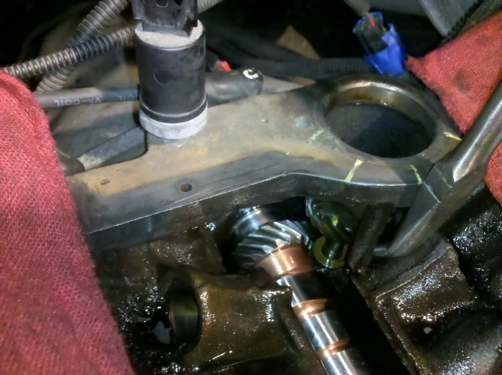
To take the old cam out and install the new cam the dizzy and the intermediate shaft needs to be removed from the motor. Now if you were to say lock the dizy shaft down and twist the cam out of the gears, remove it from the block (I would note where the cam dot is when it becomes un-meshed from the gear to give you a starting point for installing the new cam), then install the new cam and twist it back into the gears and get the dots back to perfect that should work. In theory it will but I have never tried doing it that way. Pix please you you try this. Please use brake in oil on the new cam journal BEARINGS this will help on start-up, you don't need it on the cam lobes or the lifters. Also you don't need to soak the lifters in oil, just pour some over them after they (lifters) are installed. If going with RR soak them for a little while so oil gets into the needle bearings.
Please ignore this not possible.
Edit: Make sure you point the oil holes up when installing the new lifters, and they are ezer to install with the heads off the motor.
Please ignore this not possible.
Edit: Make sure you point the oil holes up when installing the new lifters, and they are ezer to install with the heads off the motor.
Last edited by merc225hp; Feb 23, 2013 at 12:37 PM.


Champion
Joined: Oct 2009
Posts: 4,717
Likes: 10
From: N/A
I don't remember if the gear is bigger or smaller than the last journal. Maybe he can check and post if not or if is. I have always removed my dizy and shaft when installing a cam. If this can be done that way it sure would make things ezer for lot's of people.
Last edited by merc225hp; Feb 23, 2013 at 12:24 PM.
Champion
Joined: Sep 2011
Posts: 3,891
Likes: 8
From: NorCal
^^Not possible.
It's great to have a photo memory...however....things still get in the way and I'll just stress...take photos every dang step. It will help you!
I can't stress enough how important is to understand via the FSM and other sources to make sure your system (engine drivetrain) is aligned where you expect it to be.
I agree with Merc's recommendation. Much of what I did was confirmed by him as I absorbed the FSM, etc.


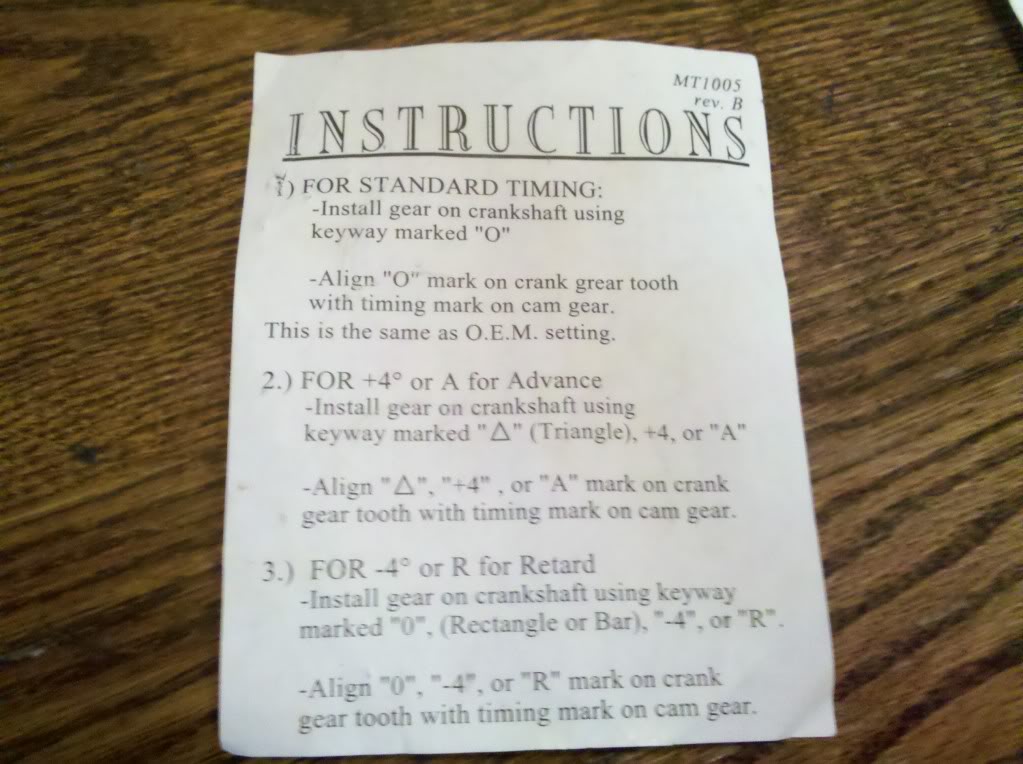
@Dodge_dude for question about adjustable cam gear. You'd follow the same directions for TDC and then clock it per that gear's instruction.
It's great to have a photo memory...however....things still get in the way and I'll just stress...take photos every dang step. It will help you!
I can't stress enough how important is to understand via the FSM and other sources to make sure your system (engine drivetrain) is aligned where you expect it to be.
I agree with Merc's recommendation. Much of what I did was confirmed by him as I absorbed the FSM, etc.
@Dodge_dude for question about adjustable cam gear. You'd follow the same directions for TDC and then clock it per that gear's instruction.
Last edited by Wh1t3NuKle; Feb 23, 2013 at 12:36 PM.

Legend
Joined: Jun 2009
Posts: 8,025
Likes: 72
From: orangeville ontario
there is 2 TDC. 1 for the compression stroke and 1 for the exhaust stroke. your crank turn 720* for ever 360* the cam turns so if you turn the crank 360* things will line up like they should.