

Fitting a Five-Speed - NV4500


Thread Starter
|
Captain

Joined: Oct 2005
Posts: 568
Likes: 8
From: The Summit, Queensland, Australia
The only V8 Chrysler products ever sold in Australia with manual transmissions were:
Trucks with 361 big block, 318 Poly and LA, perhaps a few in the fifties Hemi V8 era
Two 1960 Phoenix sedans with 3-speed gearboxes, send from Canada in error.
A very small number of small-block Valiant Chargers, possibly some others, all with the locally-made Borg-Warner 'single rail' gearbox and smaller flywheels.
Not a 360 anywhere with a manual box, none.
Administrator


Joined: Apr 2010
Posts: 87,409
Likes: 4,214
From: Clayton MI
The only V8 Chrysler products ever sold in Australia with manual transmissions were:
Trucks with 361 big block, 318 Poly and LA, perhaps a few in the fifties Hemi V8 era
Two 1960 Phoenix sedans with 3-speed gearboxes, send from Canada in error.
A very small number of small-block Valiant Chargers, possibly some others, all with the locally-made Borg-Warner 'single rail' gearbox and smaller flywheels.
Not a 360 anywhere with a manual box, none.
Trucks with 361 big block, 318 Poly and LA, perhaps a few in the fifties Hemi V8 era
Two 1960 Phoenix sedans with 3-speed gearboxes, send from Canada in error.
A very small number of small-block Valiant Chargers, possibly some others, all with the locally-made Borg-Warner 'single rail' gearbox and smaller flywheels.
Not a 360 anywhere with a manual box, none.
Yep, wild guess at 80 pounds, its like 1800 bucks from Detroit to Sydney...... Holy smokes. (FedEx.)
Last edited by HeyYou; Mar 22, 2023 at 09:09 AM.

Van & CUV Section Moderator


Joined: Nov 2006
Posts: 5,372
Likes: 115
Now I've come up against a real problem!
I should have checked, I should have realised earlier, my new bellhousing is for the larger flywheel, not the 130-tooth that I've been running. I do have a flywheel to suit except that it hasn't been balanced (either drilled or had weight added) for the 360's external balance needs.
I should have checked, I should have realised earlier, my new bellhousing is for the larger flywheel, not the 130-tooth that I've been running. I do have a flywheel to suit except that it hasn't been balanced (either drilled or had weight added) for the 360's external balance needs.
I once had this done for an automatic. But in my case the shop welded a weight to the flexplate since I had a torque converter instead of a flywheel. With the flexplate bolted to the crankshaft they did the balance procedure and drilled metal as necessary out of the weight they welded on to achieve balance.
Thread Starter
|
Captain
Joined: Oct 2005
Posts: 568
Likes: 8
From: The Summit, Queensland, Australia
That entails taking the engine out of the van and dismantling it...
Not happening, alloro. There is an acknowledged pattern of 1 13/64 holes at a set distance from the flywheel centre which gives the desired balance. I have a flywheel which shows me a similar pattern of holes which are much more readily drilled to do the same. I can duplicate that, I reckon.
Mind you, as I type this I realise that I do have a 360 crank out of an engine which I could use to get it dynamically balanced. At a pinch. Oh, and I feel confident that you'd need to have the harmonic balancer in hand to do that too. But the cost of such balancing is quite high, hundreds of dollars, way more than drilling some holes. Granted, it would be a more precise job, but the specification given by Chrysler is 19.79 inch ounces if I recall, so it's a fairly precise job too. Just not quite so precise, I guess.
And it's those hundreds of dollars needed to follow the path suggested by Hey You that will prevent that taking place. You could cut down the freight cost significantly by getting it by surface shipping, but there's still the flywheel to pay for anyway - and I have three of these larger flywheels anyway.
But what I want to know is if there is a written or schematically drawn diagram giving the chapter and verse on this alternative drilling pattern.
So, if there's anyone out there, please let me know if such a diagram exists.
Thread Starter
|
Captain
Joined: Oct 2005
Posts: 568
Likes: 8
From: The Summit, Queensland, Australia
About time I updated things a bit...
I spent an awful lot of time thinking about and planning the replacement for the cradle seen in post 21. It was necessary for two reasons, the first being that the rear housing of the gearbox would not fit between its sides at that point, the second that the increase in weight hanging from the 16SWG crossmember meant it couldn't be compromised. And it would need a bit of size reduction because of the additional height of the gearbox at that point.
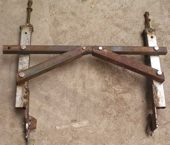
Using parts of that original cradle and pieces of 2.5mm square steel tubing, cut lengthwise to give channel sections similar to the original, I finished up with this:
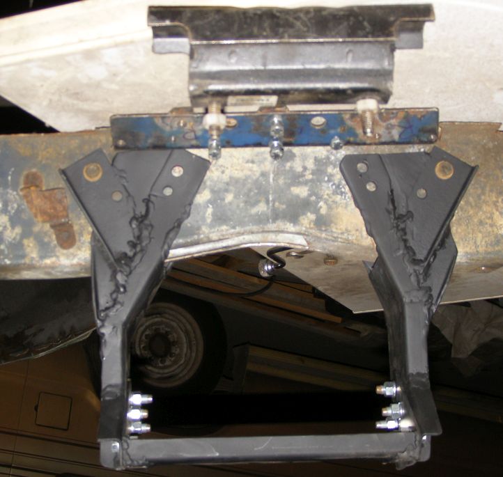
The new cradle. Shaped so it will clear the rear housing of the NV4500 and built around the original mounting points of the standard cradle, this is what I built up bolted up to a section of crossmember from the rusty vans.
I was most concerned that there should be plenty of bracing to take side loadings, as in cornering, as the original cradle was a veritable triangle and did this well. To that end you will note that instead of one bolt in each face at each end there are now four, while the unseen vertical bolt has still been retained. All of those original bolts go into captive nuts in a frame welded into the crossmember:
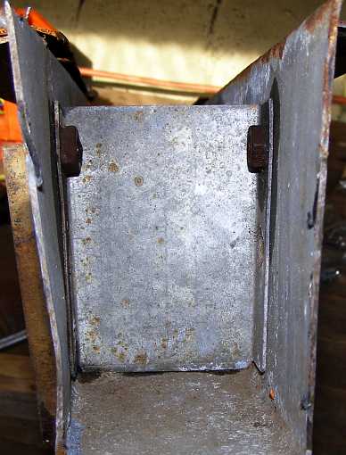
Crossmember taper and captive nuts. Here the taper of the crossmember can clearly be seen, with the fore and after captive nuts visible and the vertical one unseen because it's the other side of the little frame (or plate) to which they're attached.
Also seen at the top of my first pic here is the gearbox mount I'll be using (also pictured in post 26) and one of the braces I've made up to provide greater strength to the crossmember. This is necessary because the height of the gearbox is too great for this position as well. I'll be cutting a section about ⅝" high out of the lower part of the middle of the crossmember and then welding a new 'floor' into it over that section. But before we go further with that there's more detail in the cradle itself, or at least in the platform between the two sides which will carry the gearbox mount,
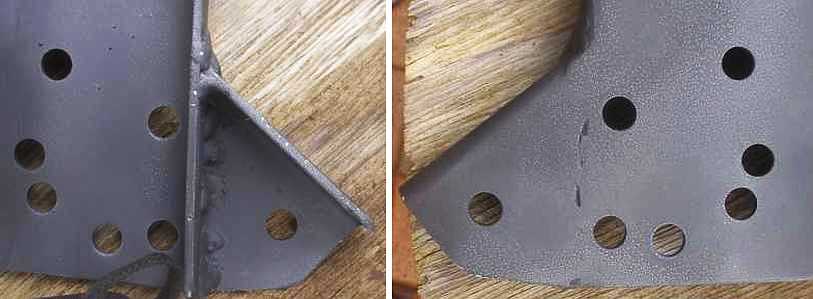
Backward location. The pad for the gearbox mount is further rearwards on the NV4500 and so I had to make provision for the mounting's platform to be moved back at the base of the new cradle.
Mount platform. Still using pieces of that 2.5mm square steel tube sliced lengthwise, this was formed and drilled precisely so that the 5/16" bolts would dowel into the two thicknesses for additional movement prevention. The load-bearing strength is aided by using the fold of the section of square tubing as I have to be seen at the right of this pair of pics. There are five bolts each side to support the platform.
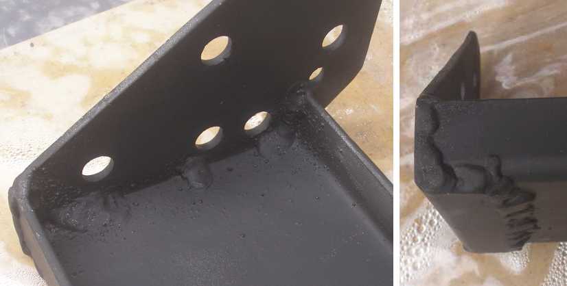
It was a lot of work, but I want it to be secure. Then there's the bracing to go into the crossmember:
Crossmember braces. These will be inserted into the crossmember and it will be drilled using the drilling jig which will be firmly bolted into place using the original cradle's mounting bolts. More 2.5mm square steel tubing sliced up.
And there's all of those captive nuts I've had to make and weld in place! A shame there's a coating of rust over most of it now, I'll sand blast and paint it some time. And end-on:
Captive nuts etc. It was quite a job making this up, while I was mindful of the prospect of the crossmember being distorted or weakening if allowed to flex, so two of these bits of heavy tube were made up, tapped and bent to give the right angle for the crossmember's taper. They will have to be 'massaged' to get just the right length when it's time to assemble it all.
Note that there are four more bolt holes in the braces not connected to the carrying of the cradle. These are, again, 5/16" UNC bolts which will be put through holes drilled with the same drilling jig and intended to dowel in place. The inner ends will have lock nuts tightened up against their captive nuts before the new cover gets welded onto the crossmember and their job will be to hold the 16SWG sheet straight and also to retain the braces in position should the cradle have to be removed and replaced at some time.
Down at the bottom end, on that platform, the mount will sit on a spacer intended to get the gearbox to the correct height, I'm hoping that will only be about �" thick, while a couple of little holes will be drilled into the platform to help water get away.
The mount, of course, has to be secured on the gearbox pad and that called for some attention as well. First of all I wasn't happy with the ⅜" bolts which took the load. Bolts, for a start, have to be screwed in and out and each time the aluminium threads are tightened they are in danger of stripping, while repeated fittings wears the thread as well. So I went to my surplus Peugeot supplies and found a couple of 12mm x 1.5mm studs which I could use, though they needed to be shortened. I re-drilled the holes and tapped them to suit, the studs get screwed in just once and any thread wear or tendency to strip is eliminated.
New studs. I used 12mm studs to replace the original bolts for the bracket on which I'll bolt the mount shown in post 26.
The bracket is made from more square steel tube, heavier again this time, with two 'slices' welded together, some drilling and hole-sawing and it bolted up nicely:
Bracket in place. Another part needing a bit of paint, but you can see that it's ready to do the job and fits up well.
Those studs, I might add, came off the cap which holds the wheel bearing into the end of the axle housing on the left here...
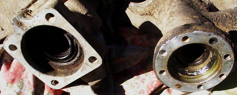
Axle tubes. These are from Peugeot 404 and 504 rear axles. I was looking more closely at these because I needed something to form up a new gearchange tower.
...which will be the main subject of the next job that needed doing.
I spent an awful lot of time thinking about and planning the replacement for the cradle seen in post 21. It was necessary for two reasons, the first being that the rear housing of the gearbox would not fit between its sides at that point, the second that the increase in weight hanging from the 16SWG crossmember meant it couldn't be compromised. And it would need a bit of size reduction because of the additional height of the gearbox at that point.
Using parts of that original cradle and pieces of 2.5mm square steel tubing, cut lengthwise to give channel sections similar to the original, I finished up with this:
The new cradle. Shaped so it will clear the rear housing of the NV4500 and built around the original mounting points of the standard cradle, this is what I built up bolted up to a section of crossmember from the rusty vans.
I was most concerned that there should be plenty of bracing to take side loadings, as in cornering, as the original cradle was a veritable triangle and did this well. To that end you will note that instead of one bolt in each face at each end there are now four, while the unseen vertical bolt has still been retained. All of those original bolts go into captive nuts in a frame welded into the crossmember:
Crossmember taper and captive nuts. Here the taper of the crossmember can clearly be seen, with the fore and after captive nuts visible and the vertical one unseen because it's the other side of the little frame (or plate) to which they're attached.
Also seen at the top of my first pic here is the gearbox mount I'll be using (also pictured in post 26) and one of the braces I've made up to provide greater strength to the crossmember. This is necessary because the height of the gearbox is too great for this position as well. I'll be cutting a section about ⅝" high out of the lower part of the middle of the crossmember and then welding a new 'floor' into it over that section. But before we go further with that there's more detail in the cradle itself, or at least in the platform between the two sides which will carry the gearbox mount,
Backward location. The pad for the gearbox mount is further rearwards on the NV4500 and so I had to make provision for the mounting's platform to be moved back at the base of the new cradle.
Mount platform. Still using pieces of that 2.5mm square steel tube sliced lengthwise, this was formed and drilled precisely so that the 5/16" bolts would dowel into the two thicknesses for additional movement prevention. The load-bearing strength is aided by using the fold of the section of square tubing as I have to be seen at the right of this pair of pics. There are five bolts each side to support the platform.
It was a lot of work, but I want it to be secure. Then there's the bracing to go into the crossmember:
Crossmember braces. These will be inserted into the crossmember and it will be drilled using the drilling jig which will be firmly bolted into place using the original cradle's mounting bolts. More 2.5mm square steel tubing sliced up.
And there's all of those captive nuts I've had to make and weld in place! A shame there's a coating of rust over most of it now, I'll sand blast and paint it some time. And end-on:
Captive nuts etc. It was quite a job making this up, while I was mindful of the prospect of the crossmember being distorted or weakening if allowed to flex, so two of these bits of heavy tube were made up, tapped and bent to give the right angle for the crossmember's taper. They will have to be 'massaged' to get just the right length when it's time to assemble it all.
Note that there are four more bolt holes in the braces not connected to the carrying of the cradle. These are, again, 5/16" UNC bolts which will be put through holes drilled with the same drilling jig and intended to dowel in place. The inner ends will have lock nuts tightened up against their captive nuts before the new cover gets welded onto the crossmember and their job will be to hold the 16SWG sheet straight and also to retain the braces in position should the cradle have to be removed and replaced at some time.
Down at the bottom end, on that platform, the mount will sit on a spacer intended to get the gearbox to the correct height, I'm hoping that will only be about �" thick, while a couple of little holes will be drilled into the platform to help water get away.
The mount, of course, has to be secured on the gearbox pad and that called for some attention as well. First of all I wasn't happy with the ⅜" bolts which took the load. Bolts, for a start, have to be screwed in and out and each time the aluminium threads are tightened they are in danger of stripping, while repeated fittings wears the thread as well. So I went to my surplus Peugeot supplies and found a couple of 12mm x 1.5mm studs which I could use, though they needed to be shortened. I re-drilled the holes and tapped them to suit, the studs get screwed in just once and any thread wear or tendency to strip is eliminated.
New studs. I used 12mm studs to replace the original bolts for the bracket on which I'll bolt the mount shown in post 26.
The bracket is made from more square steel tube, heavier again this time, with two 'slices' welded together, some drilling and hole-sawing and it bolted up nicely:
Bracket in place. Another part needing a bit of paint, but you can see that it's ready to do the job and fits up well.
Those studs, I might add, came off the cap which holds the wheel bearing into the end of the axle housing on the left here...
Axle tubes. These are from Peugeot 404 and 504 rear axles. I was looking more closely at these because I needed something to form up a new gearchange tower.
...which will be the main subject of the next job that needed doing.
Last edited by Ray Bell; Feb 2, 2024 at 03:48 PM.
Thread Starter
|
Captain
Joined: Oct 2005
Posts: 568
Likes: 8
From: The Summit, Queensland, Australia
You hear the expression, 'Steel, not plastic!'....
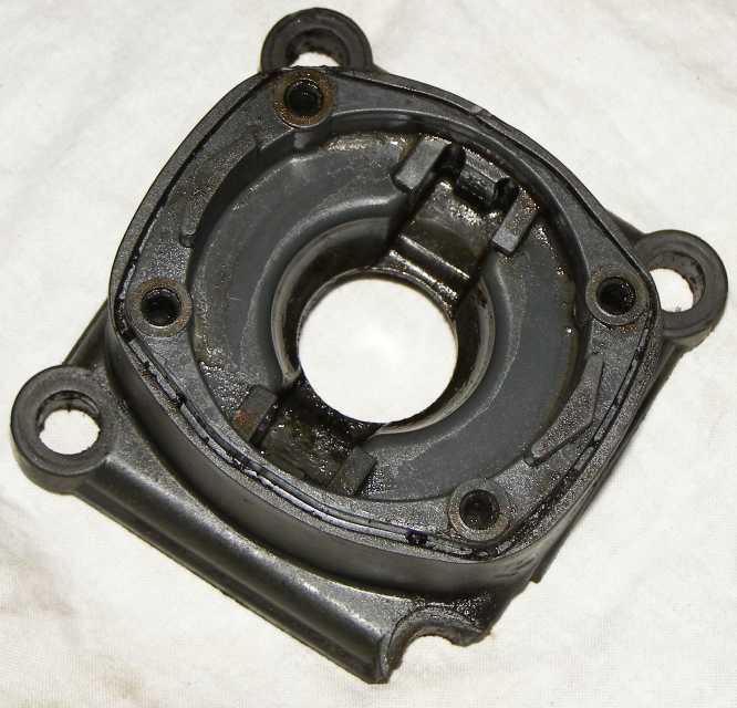
Plastic. How can you trust this stuff? This is how mine arrived and I knew I needed something better.
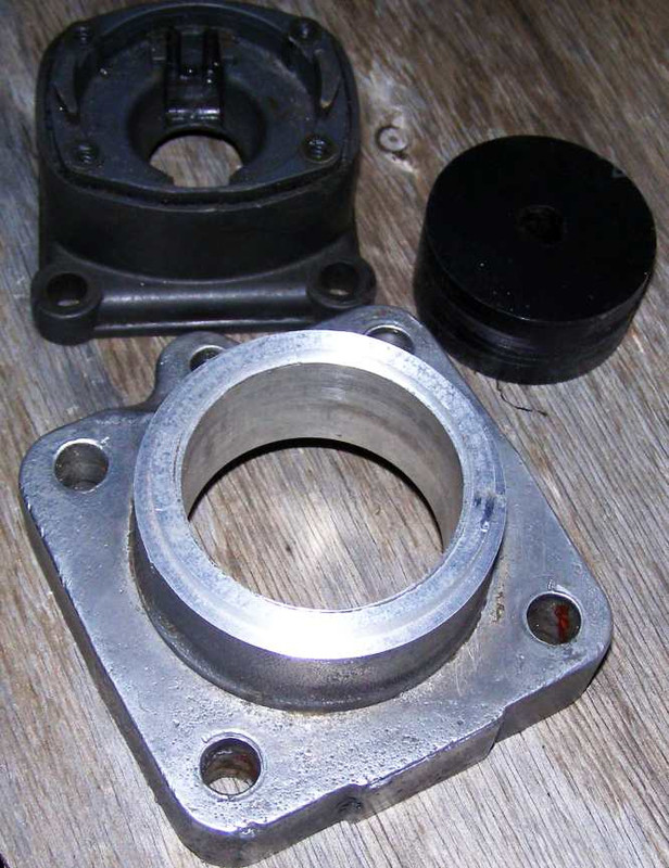
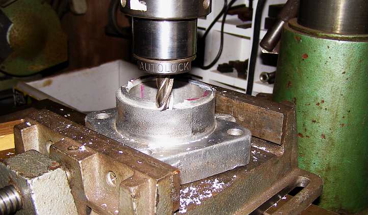
I learned that it's hard to buy them and they're still plastic, I started looking for something I could machine it up out of without spending any money on the material. Or not much, anyway, and I realised that the alloy axle housings of the Peugeot were potentially the right size. As it turned out I had to use the station wagon one, and as it had a 4-bolt pattern I'd have to 'clock' it so I could put the different 4-bolt pattern through it.
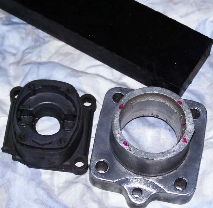
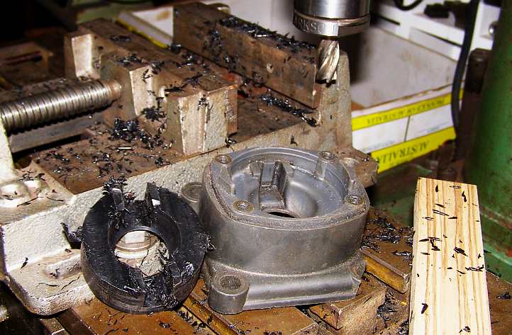
The raw materials. The aluminium piece cut from the axle tube sits alongside the busted plastic tower, the black piece is a slab of Acetal (or Delrin) from which I could machine up the core for the new tower.
So my mornings at the Men's Shed were occupied with machining all this stuff to make some sense of it.
Initial machining. Careful measuring took place first, of course, but I soon had the Acetal in a round form for insertion into its new home and the top of the alloy tower at the right height.
There was another step, not seen in these pics, and that was to turn up a piece of plate to go into the bottom of the housing to support the Acetal. This was a piece of 10mm alloy and it was held in with four screws. But there was a lot of effort went into shaping the alloy housing...
Milling the top. I was trying hard to exactly duplicate the shape of the plastic tower, for the most part I was able to do it with the help of the mill.
...and also shaping a tool for the lathe to get the right shape of socket cut into the Acetal. This also had to be milled:
Cutting it all away! It certainly looks like it as the recesses for the lever centralising were cut out on the mill.
Eventually we got to a point where I could screw the top on, I'd tapped holes down into the alloy housing for the little screws, I'd made clearance holes in the underside so the lever could move freely to each gear position and so on. In this photo you can see...
Getting there! Here we have a trial assembly. The 8mm bolts coming out the sides are actually locating the Acetal in those milled grooves, the bolt heads having been ground to a suitable size square to do that job and to ensure that the pieces which slip inside the gearchange ball don't come out too far.
And I felt it needed a bit more finishing, so a 6mm thick piece of alloy plate was turned to bolt it all down:
Neater and stronger. The 6mm alloy plate was quickly machined up. It covered up the ills of some misjudgement in doing the job.
Also in those pics you can see that I've cut away the original bolt holes from the axle tube mounting and drilled the bolt pattern to mount this as a gearchange tower on the NV4500.
Bolted on. Yes, it fits and it selects the gears.
Underside. This shows the 10mm plate which was needed to fill in the area under the Acetal and support it, also I've put some little screws through to help hold the Acetal down on it, but filing out the hole for clearance in gearchanges took a bit more handwork.
Plastic. How can you trust this stuff? This is how mine arrived and I knew I needed something better.
I learned that it's hard to buy them and they're still plastic, I started looking for something I could machine it up out of without spending any money on the material. Or not much, anyway, and I realised that the alloy axle housings of the Peugeot were potentially the right size. As it turned out I had to use the station wagon one, and as it had a 4-bolt pattern I'd have to 'clock' it so I could put the different 4-bolt pattern through it.
The raw materials. The aluminium piece cut from the axle tube sits alongside the busted plastic tower, the black piece is a slab of Acetal (or Delrin) from which I could machine up the core for the new tower.
So my mornings at the Men's Shed were occupied with machining all this stuff to make some sense of it.
Initial machining. Careful measuring took place first, of course, but I soon had the Acetal in a round form for insertion into its new home and the top of the alloy tower at the right height.
There was another step, not seen in these pics, and that was to turn up a piece of plate to go into the bottom of the housing to support the Acetal. This was a piece of 10mm alloy and it was held in with four screws. But there was a lot of effort went into shaping the alloy housing...
Milling the top. I was trying hard to exactly duplicate the shape of the plastic tower, for the most part I was able to do it with the help of the mill.
...and also shaping a tool for the lathe to get the right shape of socket cut into the Acetal. This also had to be milled:
Cutting it all away! It certainly looks like it as the recesses for the lever centralising were cut out on the mill.
Eventually we got to a point where I could screw the top on, I'd tapped holes down into the alloy housing for the little screws, I'd made clearance holes in the underside so the lever could move freely to each gear position and so on. In this photo you can see...
Getting there! Here we have a trial assembly. The 8mm bolts coming out the sides are actually locating the Acetal in those milled grooves, the bolt heads having been ground to a suitable size square to do that job and to ensure that the pieces which slip inside the gearchange ball don't come out too far.
And I felt it needed a bit more finishing, so a 6mm thick piece of alloy plate was turned to bolt it all down:
Neater and stronger. The 6mm alloy plate was quickly machined up. It covered up the ills of some misjudgement in doing the job.
Also in those pics you can see that I've cut away the original bolt holes from the axle tube mounting and drilled the bolt pattern to mount this as a gearchange tower on the NV4500.
Bolted on. Yes, it fits and it selects the gears.
Underside. This shows the 10mm plate which was needed to fill in the area under the Acetal and support it, also I've put some little screws through to help hold the Acetal down on it, but filing out the hole for clearance in gearchanges took a bit more handwork.
Last edited by Ray Bell; Jan 22, 2024 at 02:50 AM.
Thread Starter
|
Captain
Joined: Oct 2005
Posts: 568
Likes: 8
From: The Summit, Queensland, Australia
Over the end of year holiday break in 2022 I resolved that I would put in the time to get this finished. But, as always, things aren't really all that simple...
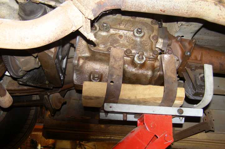
I realised that the back of the engine was unsupported once the gearbox came out. Usually you just put a jack under it and take things from there, but this wouldn't be practical for a couple of reasons, such as needing the jack to lift gearboxes in and out and needing access under the engine to do various things. I therefore made a frame to support the back of the engine from above and, as usual, it became more complex as time went on.
From the top. The basic support frame sits on pieces of wood each side of the engine bay. From there another frame is hung which actually holds the engine up.
I know, you're saying, "Why not bolt it to the bellhousing bolt holes?"
Well, I needed to be able to get to them as I sized up the bellhousing, centering it etc, didn't I? So I looked for other bolt lugs to use and there were... none!
All I had to work with was the casting itself, so I built this frame to firmly hold the vertical supports:
Solid frame. The braces between the vertical supports are there to ensure that the pieces on the bottom of these can't separate and let the engine drop. Note the long threaded bolts into the top of the vertical supports which enable a wide range of adjustment for height.
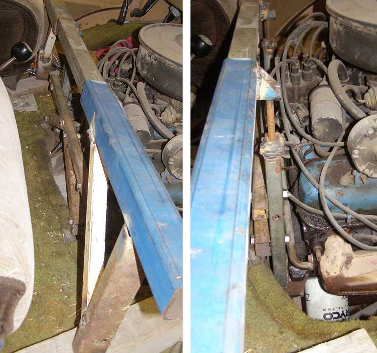
I know all of this looks pretty ugly, but the fiddling to get it all together was quite a drama. I had to shape pieces of steel to hold onto those little pieces of casting outboard of the bellhousing mounts and add bits that would restrict movement so they couldn't fall off. These pics give some idea of how it's done:
Lugs gripped. Hard to pic the full detail here, photos taken with the A833 still in place make it even harder. The left side, in the pic on the left, was very complex, the right side you can see the piece of steel has been cut to wrap around under the piece of casting.
These pics were taken with the A833 still bolted up, from underneath with the gearbox out:
Underneath. Once again, it's left and right, but in the middle is are pics showing the two bits of casting by which I was supporting the engine with this frame, I think their original purpose was to provide anchorages for the machinery when the block was being machined.
And with this adjusted to the right height I was ready to remove the A833...
Gearbox detached. My attachment to the jack in use again, a piece of two of wood under the gearbox to gain height and cradle it a little.
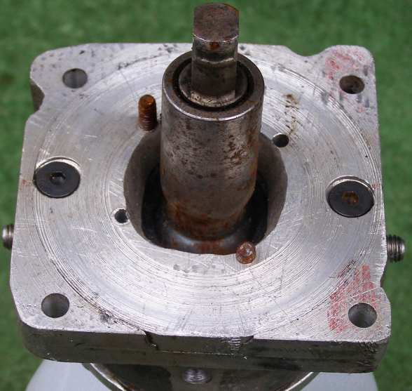
...and then remove the bellhousing and clutch:
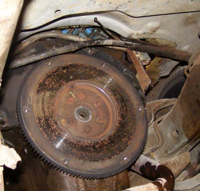
All out. With the bellhousing and clutch removed, I was ready to start the installation work.
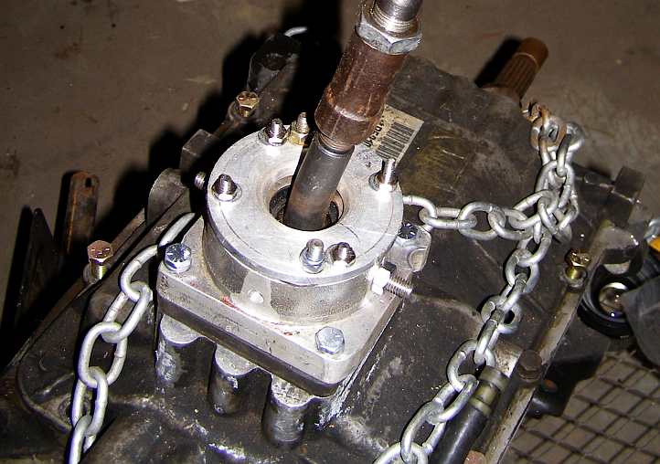
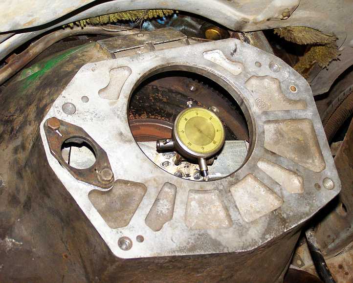
I'd made some offset dowels so I could 'dial in' the bellhousing and, to that end, I worked out a way to use the dial gauge to determine what offsets required. This would bolt to the flywheel and then I could turn it with the bellhousing in place to gauge whether or not it was on-centre.
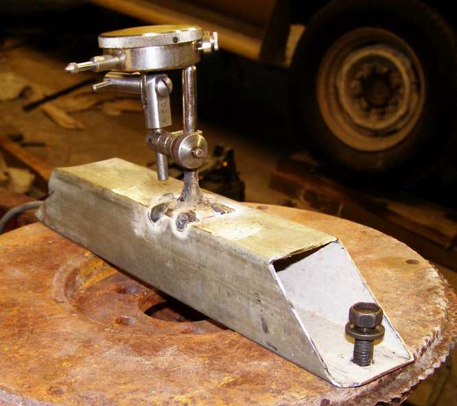
Setting up the dial gauge. A simple piece of tube bolted across the flywheel face, then mount the dial gauge in a position to suit and turn the engine. Easy?
Well, it wasn't going so well, I needed to buy another dial gauge, and I was continually getting confused lying under the van doing this and trying to work out which way things needed to be adjusted. But worse than that, doing all of this I was basically lying on my right side under the van for long periods and most lifting and moving was done on my right shoulder. Pain was setting in and a trip to the doctor revealed that I had bursitis!
Undervehicle work stopped for a long time...
I realised that the back of the engine was unsupported once the gearbox came out. Usually you just put a jack under it and take things from there, but this wouldn't be practical for a couple of reasons, such as needing the jack to lift gearboxes in and out and needing access under the engine to do various things. I therefore made a frame to support the back of the engine from above and, as usual, it became more complex as time went on.
From the top. The basic support frame sits on pieces of wood each side of the engine bay. From there another frame is hung which actually holds the engine up.
I know, you're saying, "Why not bolt it to the bellhousing bolt holes?"
Well, I needed to be able to get to them as I sized up the bellhousing, centering it etc, didn't I? So I looked for other bolt lugs to use and there were... none!
All I had to work with was the casting itself, so I built this frame to firmly hold the vertical supports:
Solid frame. The braces between the vertical supports are there to ensure that the pieces on the bottom of these can't separate and let the engine drop. Note the long threaded bolts into the top of the vertical supports which enable a wide range of adjustment for height.
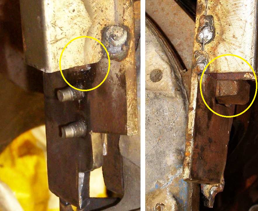
I know all of this looks pretty ugly, but the fiddling to get it all together was quite a drama. I had to shape pieces of steel to hold onto those little pieces of casting outboard of the bellhousing mounts and add bits that would restrict movement so they couldn't fall off. These pics give some idea of how it's done:
Lugs gripped. Hard to pic the full detail here, photos taken with the A833 still in place make it even harder. The left side, in the pic on the left, was very complex, the right side you can see the piece of steel has been cut to wrap around under the piece of casting.
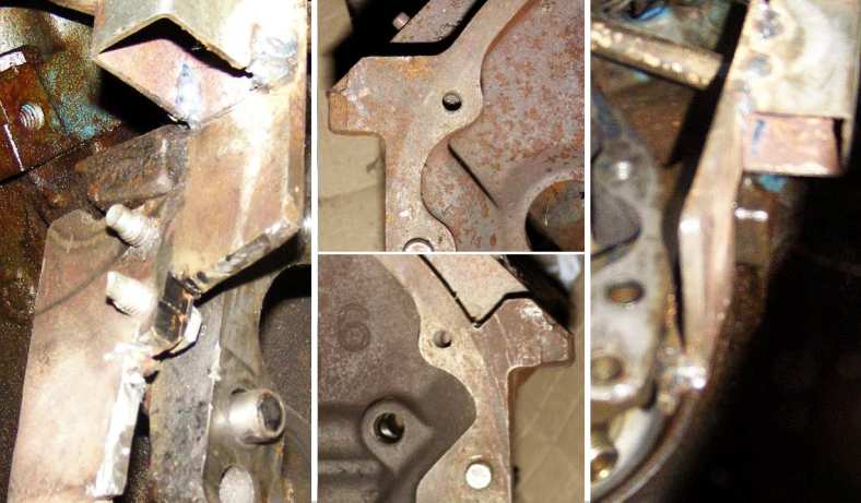
These pics were taken with the A833 still bolted up, from underneath with the gearbox out:
Underneath. Once again, it's left and right, but in the middle is are pics showing the two bits of casting by which I was supporting the engine with this frame, I think their original purpose was to provide anchorages for the machinery when the block was being machined.
And with this adjusted to the right height I was ready to remove the A833...
Gearbox detached. My attachment to the jack in use again, a piece of two of wood under the gearbox to gain height and cradle it a little.
...and then remove the bellhousing and clutch:
All out. With the bellhousing and clutch removed, I was ready to start the installation work.
I'd made some offset dowels so I could 'dial in' the bellhousing and, to that end, I worked out a way to use the dial gauge to determine what offsets required. This would bolt to the flywheel and then I could turn it with the bellhousing in place to gauge whether or not it was on-centre.
Setting up the dial gauge. A simple piece of tube bolted across the flywheel face, then mount the dial gauge in a position to suit and turn the engine. Easy?
Well, it wasn't going so well, I needed to buy another dial gauge, and I was continually getting confused lying under the van doing this and trying to work out which way things needed to be adjusted. But worse than that, doing all of this I was basically lying on my right side under the van for long periods and most lifting and moving was done on my right shoulder. Pain was setting in and a trip to the doctor revealed that I had bursitis!
Undervehicle work stopped for a long time...
Last edited by Ray Bell; Jan 27, 2024 at 06:44 AM.
Van & CUV Section Moderator
Joined: Nov 2006
Posts: 5,372
Likes: 115
I realized that the back of the engine was unsupported once the gearbox came out. Usually, you just put a jack under it and take things from there, but this wouldn't be practical for a couple of reasons, such as needing the jack to lift gearboxes in and out and needing access under the engine to do various things. I therefore made a frame to support the back of the engine from above and, as usual, it became more complex as time went on.
Solid frame. The braces between the vertical supports are there to ensure that the pieces on the bottom of these can't separate and let the engine drop. Note the long threaded bolts into the top of the vertical supports which enable a wide range of adjustment for height.
Solid frame. The braces between the vertical supports are there to ensure that the pieces on the bottom of these can't separate and let the engine drop. Note the long threaded bolts into the top of the vertical supports which enable a wide range of adjustment for height.
Thread Starter
|
Captain
Joined: Oct 2005
Posts: 568
Likes: 8
From: The Summit, Queensland, Australia
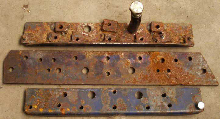
And the scrap materials lying around from which I could make up the framework...
Things just fall into place sometimes, other times you have to spend a while nutting it all out. This was a difficult thing to think through, I'd been balking for several months about getting it done, but the time came and I had to get serious. Jobs like this really shouldn't be done like that. But I get pedantic, and judging by the change you made in the first sentence above I think you do too at times.
Just for the record, the long allen-headed bolts I've used with lots of thread for adjustment are 'torque to yield' head bolts from an engine (Nissan Navara diesel?) I helped strip down at my nephew's workshop one day. Strangely, they have a 7/16" UNF thread.
As for 'skills', my welding isn't showing up too well there.
Thread Starter
|
Captain
Joined: Oct 2005
Posts: 568
Likes: 8
From: The Summit, Queensland, Australia
Work didn't stop altogether, but I was very wary of getting under the van and overworking my shoulder...
It was in the process of working out those offset dowels...
Offset dowels. Another job I did at the Men's Shed, but I still haven't perfected them and I'll have another go at it soon.
...I also looked a bit harder at the relativity of the new bellhousing and the ring gear and when hit me that I would have to use the 143-tooth flywheel and, therefore, the 11" clutch, as mentioned earlier. I'd gone to the trouble of changing the clutch plate for nothing, now it has to be changed back.
But worse than this, I have some 143-tooth flywheels, but none of them are balanced for a 360. Another job to tackle, of which more anon.
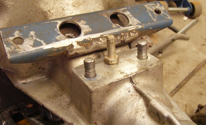
What I was able to do in all of this was determine that I wasn't happy with the way the bellhousing bolts on. The lower two bolts where it's affixed to the block are 7/16" UNC and the right hand one can't be removed with the oil filter in place. It was time, once again, to think about using studs instead of bolts. This is something I favour when things are bolted to aluminium, as I mentioned when posting about the gearbox mounting pad - "Bolts, for a start, have to be screwed in and out and each time the aluminium threads are tightened they are in danger of stripping, while repeated fittings wears the thread as well." - and I was of a mind to do all this again while I had the time and facilities at the Men's Shed.
A side benefit of having studs is that you can line things up and put them on easier than you can when you have to fish around for the bolt hole while juggling something different. So I bought some 7/16" UNC bolts and machined down the heads to the bolt size, I had some guidance at the Men's Shed to screw-cut a start to a 7/16" UNF thread on the other end and finish it with a die nut.
The result?
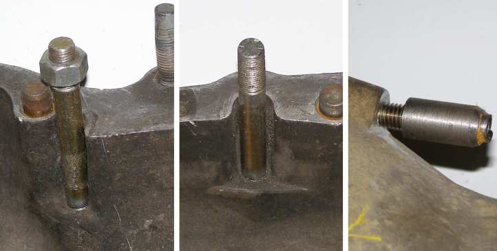
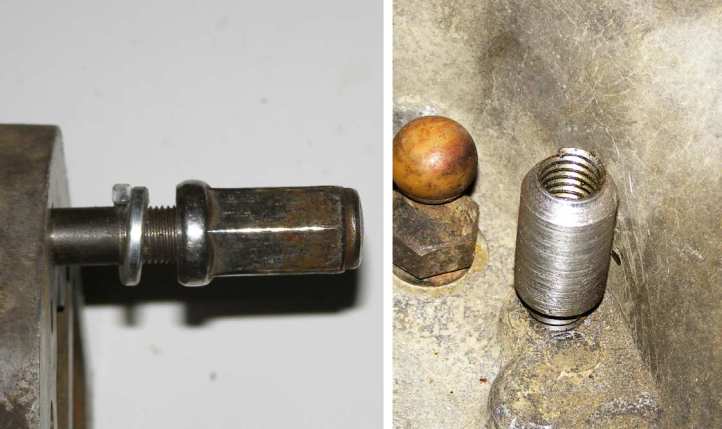
Studs, not bolts. The studs have UNC threads where they screw into the housing, UNF at the other end, which is the conventional way of doing things. This enables the thread in the aluminium housing to stay intact and carry its full load, while the nut at the other end can be tightened up to higher tensions. And I can undo the bellhousing without removing the oil filter!
Note there also that I've filed the back end of the threaded lump in the casting so I can put a locking nut on there. That nut is not yet finished, I still have to work out what do do, probably grind a hex on it - or maybe cut it back and weld an allen head onto it?
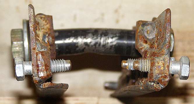
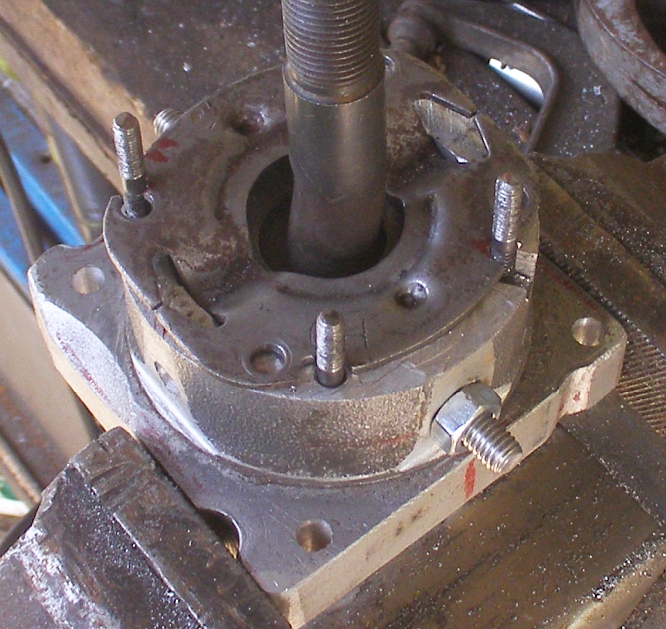
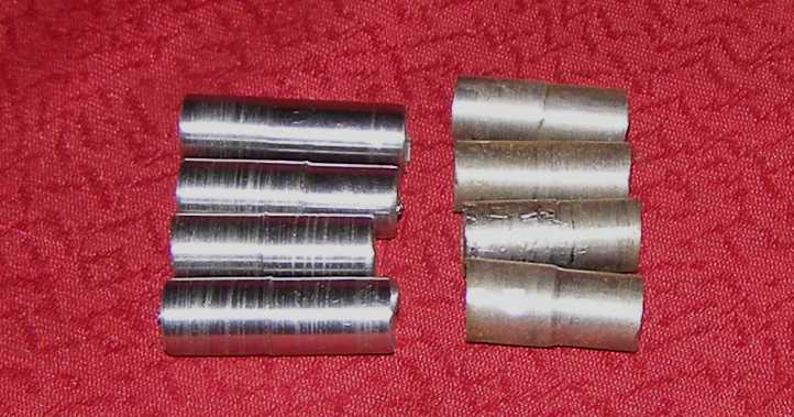
And I did the same thing at the other end of the bellhousing, putting studs into the housing so I can more readily guide the gearbox into place and so the threads in the aluminium don't get worn out and fail. The starting point with these was a handful of head bolts from an LA engine:
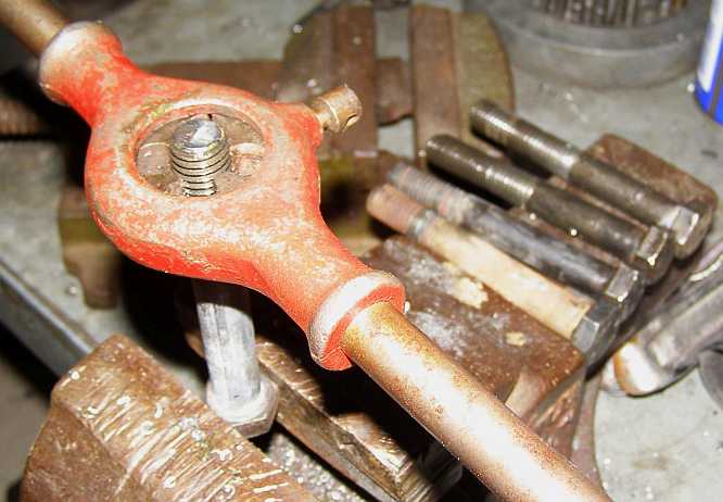
Cutting extra thread. First job with these was to extend the �" UNC thread as the holes in the bellhousing go quite deep.
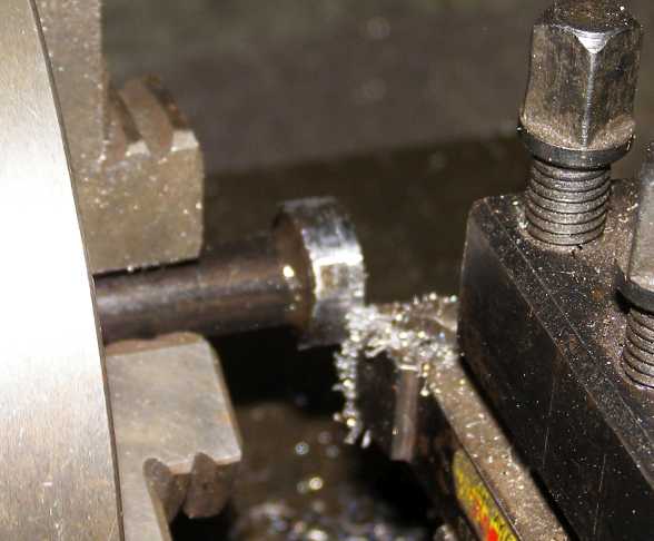
Heads machined down. Once again on the Men's Shed lathe, I machined the heads off the head bolts and cut that end down to make a good start for the UNF thread which would be cut that end.
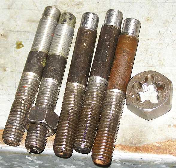
Almost complete. I made five in case something went wrong, the UNF threads were cut far enough on to leave a blank shank about the same as the thickness of the gearbox flange onto which these would be bolted.
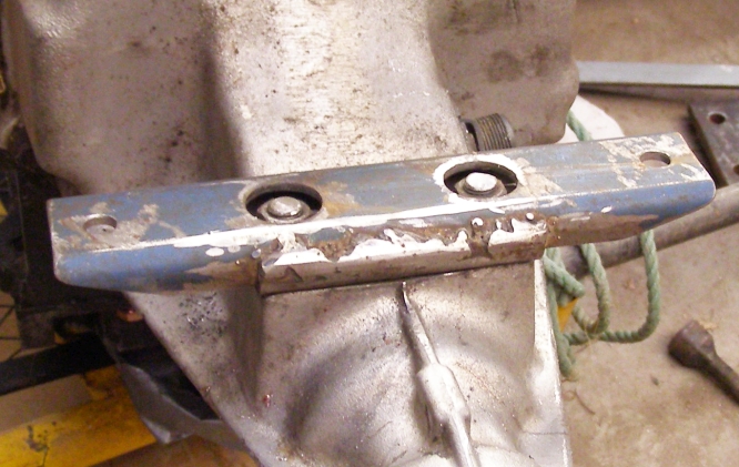
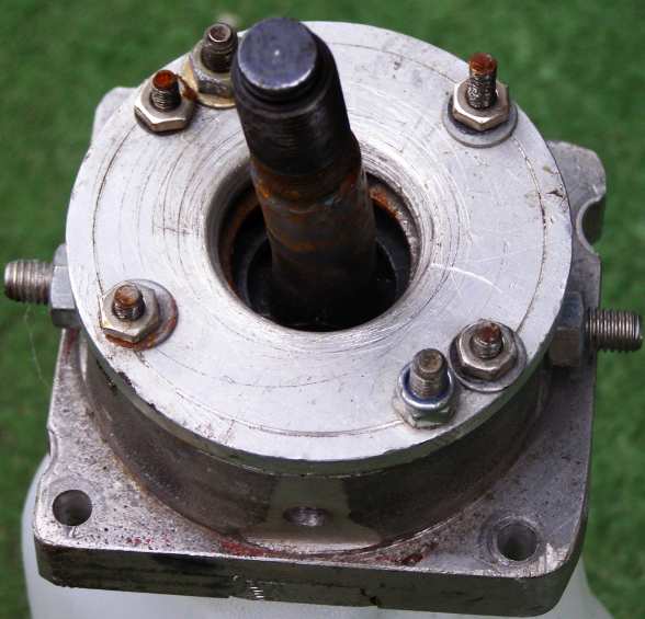
Seeing as I was going to this trouble, I thought I'd use some long chromed wheel nuts that were lying around too...
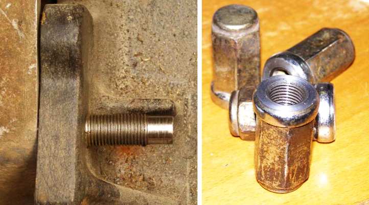
Studs and nuts. This is how the studs fit up while the nuts had the taper machined off so they'd present a nice flat surface...
A sturdy spring washer completes the job while inside the bellhousing I'm putting some more locknuts like those on the 7/16" studs"
With the spring washer. As can be seen, a bit more work still to be done. Again, I'm not sure what I'll do about the locknuts, they'll have to be done up tight so they don't fall off into the clutch works while there's not room in there to fit conventional hex nuts - which have a �" hex.
Basically I have two problems slowing me down with all of this. My present work requires that I am away a lot, and with the Men's Shed only available two mornings a week, it often happens that I'm away on those mornings. Not to mention that I've moved house and I'm now about 100 miles away from the Men's Shed anyway. The other is that doing near-countless miles in my work means my work vehicle frequently needs work done on it.
And it's a Ford... need I say more?
It was in the process of working out those offset dowels...
Offset dowels. Another job I did at the Men's Shed, but I still haven't perfected them and I'll have another go at it soon.
...I also looked a bit harder at the relativity of the new bellhousing and the ring gear and when hit me that I would have to use the 143-tooth flywheel and, therefore, the 11" clutch, as mentioned earlier. I'd gone to the trouble of changing the clutch plate for nothing, now it has to be changed back.
But worse than this, I have some 143-tooth flywheels, but none of them are balanced for a 360. Another job to tackle, of which more anon.
What I was able to do in all of this was determine that I wasn't happy with the way the bellhousing bolts on. The lower two bolts where it's affixed to the block are 7/16" UNC and the right hand one can't be removed with the oil filter in place. It was time, once again, to think about using studs instead of bolts. This is something I favour when things are bolted to aluminium, as I mentioned when posting about the gearbox mounting pad - "Bolts, for a start, have to be screwed in and out and each time the aluminium threads are tightened they are in danger of stripping, while repeated fittings wears the thread as well." - and I was of a mind to do all this again while I had the time and facilities at the Men's Shed.
A side benefit of having studs is that you can line things up and put them on easier than you can when you have to fish around for the bolt hole while juggling something different. So I bought some 7/16" UNC bolts and machined down the heads to the bolt size, I had some guidance at the Men's Shed to screw-cut a start to a 7/16" UNF thread on the other end and finish it with a die nut.
The result?
Studs, not bolts. The studs have UNC threads where they screw into the housing, UNF at the other end, which is the conventional way of doing things. This enables the thread in the aluminium housing to stay intact and carry its full load, while the nut at the other end can be tightened up to higher tensions. And I can undo the bellhousing without removing the oil filter!
Note there also that I've filed the back end of the threaded lump in the casting so I can put a locking nut on there. That nut is not yet finished, I still have to work out what do do, probably grind a hex on it - or maybe cut it back and weld an allen head onto it?
And I did the same thing at the other end of the bellhousing, putting studs into the housing so I can more readily guide the gearbox into place and so the threads in the aluminium don't get worn out and fail. The starting point with these was a handful of head bolts from an LA engine:
Cutting extra thread. First job with these was to extend the �" UNC thread as the holes in the bellhousing go quite deep.
Heads machined down. Once again on the Men's Shed lathe, I machined the heads off the head bolts and cut that end down to make a good start for the UNF thread which would be cut that end.
Almost complete. I made five in case something went wrong, the UNF threads were cut far enough on to leave a blank shank about the same as the thickness of the gearbox flange onto which these would be bolted.
Seeing as I was going to this trouble, I thought I'd use some long chromed wheel nuts that were lying around too...
Studs and nuts. This is how the studs fit up while the nuts had the taper machined off so they'd present a nice flat surface...
A sturdy spring washer completes the job while inside the bellhousing I'm putting some more locknuts like those on the 7/16" studs"
With the spring washer. As can be seen, a bit more work still to be done. Again, I'm not sure what I'll do about the locknuts, they'll have to be done up tight so they don't fall off into the clutch works while there's not room in there to fit conventional hex nuts - which have a �" hex.
Basically I have two problems slowing me down with all of this. My present work requires that I am away a lot, and with the Men's Shed only available two mornings a week, it often happens that I'm away on those mornings. Not to mention that I've moved house and I'm now about 100 miles away from the Men's Shed anyway. The other is that doing near-countless miles in my work means my work vehicle frequently needs work done on it.
And it's a Ford... need I say more?
Last edited by Ray Bell; Feb 2, 2024 at 03:33 PM.