When you click on links to various merchants on this site and make a purchase, this can result in this site earning a commission. Affiliate programs and affiliations include, but are not limited to, the eBay Partner Network.
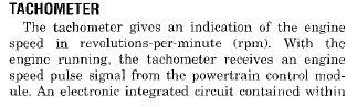
Now on page 8E-4, here's what it says about the tach:
Now it says on the same page that the speedometer receives its signal right from the VSS, so the speedometer is independent of the PCM. What it doesn't say is which wires do what on the speedo.
Now on page 8E-4, here's what it says about the tach:
Now it says on the same page that the speedometer receives its signal right from the VSS, so the speedometer is independent of the PCM. What it doesn't say is which wires do what on the speedo.
White wire with orange trace is VSS input signal. So far as I can tell, that should be the only wire you need to make the speedo work.
Three wires at VSS:
Light blue: Sensor ground
Orange: 5 volt supply.
Both of those are to/from the PCM
White with orange trace: Signal wire. This has a splice that also goes to the PCM. Probably for cruise, and a couple other purposes. (trans for instance....)
Shouldn't have to do anything on the back of the speedo, so long as all the wires are still in the connector for the cluster. Just make sure you are getting 5 volts to the sensor.
Well that's the problem, I will be running a custom cluster, so while I may be able to use the factory speedo, I might not be able to reuse the PCB on the back.


 The speedo will work either way, I should think. Just the odo may run backwards.